2014 Seat Toledo warning light
[x] Cancel search: warning lightPage 152 of 200

Advice
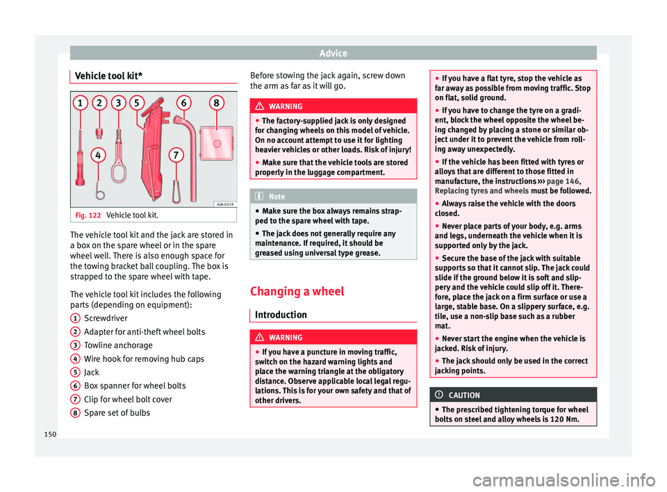
Vehicle tool kit* Fig. 122
Vehicle tool kit. The vehicle tool kit and the jack are stored in
a box on the spare wheel or in the spare
wheel well. There is also enough space for
the towing bracket ball coupling. The box is
strapped to the spare wheel with tape.
The vehicle tool kit includes the following
parts (depending on equipment):
Screwdriver
Adapter for anti-theft wheel bolts
Towline anchorage
Wire hook for removing hub caps
Jack
Box spanner for wheel bolts
Clip for wheel bolt cover
Spare set of bulbs
1 2
3
4
5
6
7
8 Before stowing the jack again, screw down
the arm as far as it will go.
WARNING
● The factory-supplied jack is only designed
for changing wheels on this model of vehicle.
On no account attempt to use it for lighting
heavier vehicles or other loads. Risk of injury!
● Make sure that the vehicle tools are stored
properly in the luggage compartment. Note
● Make sure the box always remains strap-
ped to the spare wheel with tape.
● The jack does not generally require any
maintenance. If required, it should be
greased using universal type grease. Changing a wheel
Introduction WARNING
● If you have a puncture in moving traffic,
switch on the hazard warning lights and
place the warning triangle at the obligatory
distance. Observe applicable local legal regu-
lations. This is for your own safety and that of
other drivers. ●
If you have a flat tyre, stop the vehicle as
far away as possible from moving traffic. Stop
on flat, solid ground.
● If you have to change the tyre on a gradi-
ent, block the wheel opposite the wheel be-
ing changed by placing a stone or similar ob-
ject under it to prevent the vehicle from roll-
ing away unexpectedly.
● If the vehicle has been fitted with tyres or
alloys that are different to those fitted in
manufacture, the instructions ››› page 146,
Replacing tyres and wheels must be followed.
● Always raise the vehicle with the doors
closed.
● Never place parts of your body, e.g. arms
and legs, underneath the vehicle when it is
supported only by the jack.
● Secure the base of the jack with suitable
supports so that it cannot slip. The jack could
slide if the ground below it is soft and slip-
pery and the vehicle could slip off it. There-
fore, place the jack on a firm surface or use a
large, stable base. On a slippery surface, e.g.
tile, use a non-slip base such as a rubber
mat.
● Never start the engine when the vehicle is
jacked. Risk of injury.
● The jack should only be used in the correct
jacking points. CAUTION
● The prescribed tightening torque for wheel
bolts on steel and alloy wheels is 120 Nm. 150
Page 155 of 200

Emergencies
Loosening wheel bolts – Fit the box spanner as far as it will go over
the wheel bolt 1)
.
– Grip the end of the box spanner and turn
the wheel bolt about one turn anti-clock-
w i
se ››› Fig. 124.
Tightening wheel bolts – Fit the box spanner as far as it will go over
the wheel bolt 1)
.
– Grip the box spanner as close to the end as
possible and tighten the bolt firmly by turn-
ing clockwise. WARNING
The wheel bolts should only be loosened
slightly (about one turn) before raising the
vehicle with the jack. Risk of accident! Note
If the wheel bolt is very tight, it may be pos-
sible to loosen it by pushing down the end of
the box spanner carefully with your foot. Hold
on to the vehicle for support and take care
not to slip. Lifting the vehicle
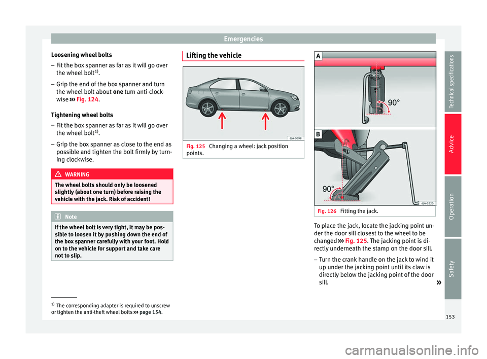
Fig. 125
Changing a wheel: jack position
points. Fig. 126
Fitting the jack. To place the jack, locate the jacking point un-
der the door sill closest to the wheel to be
changed
››› Fig. 125 . The jacking point is di-
r ectly
underneath the stamp on the door sill.
– Turn the crank handle on the jack to wind it
up under the jacking point until its claw is
directly below the jacking point of the door
sill.
»1)
The corresponding adapter is required to unscrew
or tighten the anti-theft wheel bolts ››› page 154.
153
Technical specifications
Advice
Operation
Safety
Page 159 of 200

Emergencies
Check after 10 minutes of driving Check the tyre pressure after 10 minutes of
driving!
If the tyre pressure is less than 1.3 bar
(18.8 psi/130 kPa):
– Do not drive on! The tyr e cannot be suffi-
ciently filled using the tyre repair kit.
– See professional assistance.
If the tyre pressure is greater than 1.3 bar
(18.8 psi/130 kPa): – Correct the tyre pressure again to the cor-
rect value (see inside of the fuel tank flap).
– Carefully drive to the nearest specialised
workshop at a maximum speed of 80 km/h
(50 mph).
Jump-starting Introduction If the engine fails to start because of a dis-
charged battery, the battery can be connec-
ted to the battery of another vehicle to start
the engine. Suitable jump leads are required.
Both batteries need to have nominal voltage
of 12 V. The
capacity (Ah) of the back-up bat- t
er
y should not be notably less than the
drained battery.
Jump leads
The jump leads must be heavy enough to car-
ry the starter current and must be fitted with
insulated battery clamps. Refer to the instruc-
tions given by the manufacturer.
Positive cable – usually red
Neg
ative cable
– usually black WARNING
● A flat battery can also freeze at tempera-
tures slightly below to 0 °C (32 °F). Do not at-
tempt to start the vehicle with a frozen bat-
tery. Risk of explosion!
● Please note the safety warnings referring to
working in the engine compartment
››› page 132.
● The non-in s
ulated parts of the battery
clamps must not be allowed to touch. Addi-
tionally, the jump lead attached to the posi-
tive battery terminal must not touch metal
parts of the vehicle. Risk of short circuit!
● Do not connect the negative lead to the
negative terminal of the discharged battery.
In the event of sparks when starting the en-
gine, the explosive gas given off by the bat-
tery could catch fire.
● Position the jump leads in such a way that
they cannot come into contact with any mov-
ing parts in the engine compartment. ●
Do not bend over the battery. Risk of acid
burns!
● The screw plugs on the battery cells must
be screwed in firmly.
● Keep sources of fire (flames, lit cigarettes,
etc.) away from the battery. - Risk of explo-
sion!
● Never use the jump leads on batteries in
which the electrolyte level is too low. Risk of
explosion and acid burns. Note
● The vehicles must not touch each other, as
electricity could flow as soon as the positive
terminals are connected.
● The discharged battery must be properly
connected to the vehicle electrical system.
● The jump leads should be checked in a spe-
cialist vehicle battery shop. 157
Technical specifications
Advice
Operation
Safety
Page 160 of 200

Advice
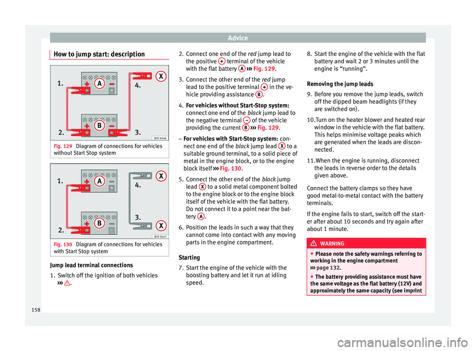
How to jump start: description Fig. 129
Diagram of connections for vehicles
without Start Stop system Fig. 130
Diagram of connections for vehicles
with Start Stop system Jump lead terminal connections
1. Switch off the ignition of both vehicles
››› . 2. Connect one end of the
red jump lead to
the po s
itive + terminal of the vehicle
with the flat battery A
››› Fig. 129 .
3. C
onnect the other end of the red
jump
lead to the positive terminal + in the ve-
hicle providing assistance B .
4. For vehicles without Start-Stop system:
connect one end of the black jump lead to
the negative terminal – of the vehicle
providing the current B
››› Fig. 129 .
– For
vehicles with Start-Stop system: con-
nect one end of the black jump lead X to a
suitable ground terminal, to a solid piece of
metal in the engine block, or to the engine
block itself ››› Fig. 130 .
5. C
onnect the other end of the black jump
lead X to a solid metal component bolted
to the engine block or to the engine block
itself of the vehicle with the flat battery.
Do not connect it to a point near the bat-
tery A .
6. Position the leads in such a way that they cannot come into contact with any moving
parts in the engine compartment.
Starting
7. Start the engine of the vehicle with the boosting battery and let it run at idling
speed. 8. Start the engine of the vehicle with the flat
battery and wait 2 or 3 minutes until the
engine is “running”.
Removing the jump leads
9. Before you remove the jump leads, switch off the dipped beam headlights (if they
are switched on).
10.Turn on the heater blower and heated rear window in the vehicle with the flat battery.
This helps minimise voltage peaks which
are generated when the leads are discon-
nected.
11. When the engine is running, disconnect
the l e
ads in reverse order to the details
given above.
Connect the battery clamps so they have
good metal-to-metal contact with the battery
terminals.
If the engine fails to start, switch off the start-
er after about 10 seconds and try again after
about 1 minute. WARNING
● Please note the safety warnings referring to
working in the engine compartment
››› page 132.
● The b att
ery providing assistance must have
the same voltage as the flat battery (12V) and
approximately the same capacity (see imprint 158
Page 165 of 200

Fuses and bulbs
Changing the rear window wiper
blade* Fig. 137
Rear window wiper blade. Taking off the wiper blade
–
Lift the rear window wiper arm away from
the glass moving the blade slightly in the
direction of the arm – arrow A
››› Fig. 137 .
– Ho l
d the top of the rear window wiper arm
with one hand.
– Unlock the catch 1 with the other hand
and remove the blade in the direction of ar-
row B .
Fitting the wiper blade – Slide the blade fully until it clicks into posi-
tion.
– Check that the wiper is correctly secured.
– Fold the rear window wiper arm back down
onto the glass. Fuses and bulbs
Fuses Introduction Due to the constant updating of vehicles,
fuse assignments based on equipment and
the use of the same fuse for various electrical
components, it is not possible to provide an
up-to-date summary of the fuse positions for
the electrical components at the time this
manual was printed. For detailed information
about the fuse positions, please consult a
technical service.
In general, a fuse can be assigned to various
electrical components. Likewise, an electrical
component can be protected by several
fuses.
Only replace fuses when the cause of the
problem has been solved. If a newly inserted
fuse blows after a short time, you must have
the electrical system checked by a special-
ised workshop as soon as possible.
Additional information and warnings:
● Working in the engine compartment
››› page 132 . WARNING
The high voltages in the electrical system can
give serious electrical shocks, causing burns
and even death!
● Never touch the electrical wiring of the igni-
tion system.
● Take care not to cause short circuits in the
electrical system. WARNING
Using unsuitable fuses, repairing fuses or
bridging a current circuit without fuses can
cause a fire and serious injury.
● Never use a fuse with a higher value. Only
replace fuses with a fuse of the same amper-
age (same colour and markings) and size.
● Never repair a fuse.
● Never replace a fuse by a metal strip, staple
or similar. CAUTION
● To prevent damage to the vehicle's electric
system, before replacing a fuse always turn
off the ignition, the lights and all electrical
elements and remove the key from the igni-
tion.
● If you replace a fuse with higher-rating
fuse, you could cause damage to another part
of the electrical system.
● Protect the fuse boxes when open to pre-
vent the entry of dust or humidity as they can
damage the electrical system. » 163
Technical specifications
Advice
Operation
Safety
Page 168 of 200

Advice
● Replace the cover again or close the fuse
box lid. CAUTION
If you replace a fuse with higher-rating fuse,
you could cause damage to another part of
the electrical system. Changing bulbs
Introduction Changing bulbs requires a certain degree of
practical skill. If in doubt, we recommend you
have defective bulbs changed by a special-
ised service or, in case of an emergency,
seek professional assistance.
●
Switch off the ignition and all of the lights
before changing a bulb.
● Do not touch the glass part of the bulb with
your bare hands. The fingerprints left on the
glass will vaporise as a result of the heat gen-
erated by the bulb, reducing bulb life and
causing condensation on the reflector sur-
face, thus reducing effectiveness.
● A bulb must only be replaced by one of the
same type. The type is indicated on the bulb,
either on the glass part or on the base.
● There is a storage area for the bulb box in
the spare wheel well or below the carpet in
the luggage compartment. The light source used for each function is lis-
ted below:
Double headlights
H7 Long Life
H7
W5W Long Life PY21W NA P21W Super Long Life WARNING
● Take particular care when working on com-
ponents in the engine compartment if the en-
gine is warm. Risk of burns.
● Bulbs are highly sensitive to pressure. The
glass can break when you touch the bulb,
causing injury.
● The high voltage element of gas discharge
bulbs* (xenon light) must be handled correct-
ly. Otherwise, there is a risk of death.
● When changing bulbs, please take care not
to injure yourself on sharp parts in the head-
light housing. CAUTION
● Remove the ignition key before working on
the electric system. Otherwise, a short circuit
could occur.
● Switch off the lights and the parking light
before changing a bulb. Dipped beam:
Main beam:
Side lights:
Turn signals:
Daytime driving lights: For the sake of the environment
Please ask your specialist retailer how to dis-
pose of used bulbs in the proper manner. Note
● Depending on weather conditions (cold or
wet), the front lights, the fog lights, the rear
lights and the turn signals may be temporari-
ly misted. This has no influence on the useful
life of the lighting system. By switching on
the lights, the area through which the beam
of light is projected will quickly be demisted.
However, the edges may continue to be mis-
ted.
● Please check at regular intervals that all
lighting (especially the exterior lighting) on
your vehicle is functioning properly. This is
not only in the interest of your own safety,
but also that of all other road users.
● Before changing a bulb, make sure you
have the correct new bulb.
● Do not touch the glass part of the bulb with
your bare hands, use a cloth or paper towel
instead. Otherwise, the fingerprints left on
the glass will vaporise as a result of the heat
generated by the bulb, they will be deposited
on the reflector and damage its surface. 166
Page 178 of 200

Technical specifications
Calculation of fuel consumption
The consumption values have been calcula-
ted based on measurements performed or
supervised by certified CE laboratories ac-
cording to the latest version of directives
715/2007/EC and 80/1268/CEE (for more in-
formation consult the European Union Publi-
cations Office at EUR-Lex: © European Union,
http://eur-lex.europa.eu/en/index.htm) and
are valid for the kerb weight indicated for the
vehicle. Note
In practice, and considering all the factors
mentioned here, consumption values can dif-
fer from those calculated in the current Euro-
pean regulations. Weights
Kerb weight refers to the basic model with a
fuel tank filled to 90% capacity and without
optional extras. The figure quoted includes
75 kg to allow for the weight of the driver.
Special versions, optional equipment fittings
or retro-fitting accessories will increase the
weight of the vehicle
››› .
WARNING
● Please note that the centre of gravity may
shift when transporting heavy objects; this may affect vehicle handling and lead to an ac-
cident. Always adjust your speed and driving
style to suit road conditions and require-
ments.
●
Never exceed the gross axle weight rating
or the gross vehicle weight rating. If the per-
missible axle load or the permissible total
weight is exceeded, the driving characteris-
tics of the vehicle may change, which could
lead to accidents, injuries and damage to the
vehicle. Towing a trailer
Trailer weights Trailer weight
The trailer weights and drawbar loads ap-
proved are selected in intensive trials accord-
ing to precisely defined criteria. The ap-
proved trailer weights are valid for vehicles in
the
EU
for maximum speeds of 80 km/h (50
mph) (in c ertain circumstances up to 100
km/h (62 mph)). The figures may be different
in other countries. All data in the official vehi-
cle documentation takes precedence over
these data at all times ››› .
Drawbar loads
The maximum
permitted drawbar load on the
b
all joint of the towing bracket must not ex-
ceed
50 kg. In the interest of road safety, we recommend
that you always tow approaching the maxi-
mum drawbar load. The response of the trail-
er on the road will be poor, if the drawbar
load is too small.
If the maximum permissible drawbar load
cannot be met (e.g. with small, empty and
light-weight single axle trailers or tandem
axle trailers with a wheelbase of less than 1
metre), a minimum of 4% of the actual trailer
weight is legally required for the drawbar
load.
WARNING
● For safety reasons, do not exceed the 80
km/h (50 mph) limit. This is also valid in
countries where higher speeds are permitted.
● Never exceed the maximum trailer weights
or the drawbar load. If the permissible axle
load or the permissible total weight is excee-
ded, the driving characteristics of the vehicle
may change, leading to accidents, injuries
and damage to the vehicle. 176
Page 179 of 200

Technical specifications
Wheels Tyre pressure, snow chains, wheel
bolts Tyre pressures
The sticker with the tyre pressure values can
be found on the inside of the fuel tank flap.
The tyre pressure values given there are for
cold tyres. Do not reduce the slightly raised
pr
e
ssures of warm tyres ››› .
Snow chains
Snow chains may be fitted only to the front
wheels .
C on
sult the section “wheels” of this manual.
Wheel bolts
After the wheels have been changed, the
tightening torque
of the wheel bolts should
be checked as soon as possible with a torque
wrench ››› . The tightening torque for steel
and alloy wheels is 120 Nm. WARNING
● Check the tyre pressure at least once per
month. Checking the tyre pressure is very im-
portant. If the tyre pressure is too high or too
low, there is an increased danger of accidents
- particularly at high speeds. ●
If the tightening torque of the wheel bolts
is too low, they could loosen while the vehi-
cle is in motion. Risk of accident! If the tight-
ening torque is too high, the wheel bolts and
threads can be damaged. Note
We recommend that you ask your Technical
Service for information about appropriate
wheel, tyre and snow chain size. 177
Technical specifications
Advice
Operation
Safety