2014 Seat Ibiza 5D wheel
[x] Cancel search: wheelPage 74 of 240

OperationBut-
tonShort pressLong press
RadioAudio CD / MP3 CDAUX-INPND (Micro SD/Blue- tooth Audio)RadioAudio CD / MP3 CDAUX-INPND (Micro SD/Blue-tooth Audio)
MODECyclical source changeCyclical source change
a)Function only available if the vehicle has a telephone unit (other than PND)
Key functions 1)
If there is an in-
coming callPress once
: accept call
During a callPress once: it ends the call
Without an in-
coming call
Press once: the PND goes into tele-
phone mode (if not already in this
mode).
Press twice : opens the call history of
the telephone connected to the PND.
Press three times : the first number in
the call history is called.
If no telephone
is connectedPress once : the PND will display the
message “There is no telephone con-
nected, please connect a telephone ”. Bluetooth System*
General information This system allows you to connect your mo-
bile phone via Bluetooth connection and to
use the hands-free mode.
The hands-free device means that the tele-
phone can be used inside the vehicle; the
driver will not have to remove their hands
from the steering wheel nor will be distracted
from traffic.
Available functions include making calls in
hands-free mode, access to the mobile
phone address book, access to the call list
and control of the voice recognition system.
Before using the Bluetooth system, the mo-
bile phone should be connected to the vehi-
cle installation via Bluetooth
›››
page 74. Switching on/off
The Bluetooth system is activated when the
ignition is turned on and it is deactivated
when the key is removed from the ignition.
With the system activated, if the button
››› Fig. 80
(“PTT”) is pressed the voice con-
trol activates, and if there is no telephone
connected, Bluetooth visibility is turned on
and a search for a telephone begins.
If there is a call in process when the system
is deactivated, the active call is not cancel-
led, but transferred to the mobile phone.
Bluetooth
Use compatible Bluetooth devices only. For
more information about compatible Blue-
tooth products, consult your dealership or
the SEAT website. 1)
If a telephone is already connected via Bluetooth
to the PND
72
Page 78 of 240

OperationBut-
tonFunction
“Push to talk” or “PTT” button.
Short press:
start or cancel the speech control
system, interrupt message in process in order
to talk promptly, turn on Bluetooth visible for
3 minutes.
VOL + /
VOL –Short press: adjust volume of telephone func-
tion.
Short press:
Answer, Start, End a call.
Long press: Decline an incoming call, transfer
active call to private mode. Voice control
The voice control system is activated with the
button
›››
Fig. 80
(“P
TT”).
Th
anks to the voice control you can use many
telephone functions without having to take
your eyes off the road or your hands off the
steering wheel.
Dialogue
is the time during which the voice
control system transmits messages and can
receive spoken orders (commands).
If a call is received, then the dialogue is im-
mediately interrupted. You can use the
HELP in any part of the
menu. If you have any doubts or cannot de-
cide the Command to use, the system will
provide you with the available options.
You can CANCEL in any part of the menu.
Adju
sting the volume
You can change the sound volume at any
time with the radio button or with the buttons
on the multifunction control.
The volume transmitted by the speaker de-
pends, among other aspects, on the volume
transmitted by the mobile. If the volume of
the mobile is low, or on silent, it is possible
that no sound will be heard through the vehi-
cle speaker.
Adjust the volume of your Bluetooth device to
the maximum.
Do not leave headphones connected to the
Bluetooth device when you wish to use the
hands free system.
Complying with these requirements, if the
speaker volume is very high, adjust it using
the controls on the steering wheel ››› page 71
or the volume control on the radio. Connecting voice control (Dialogue)
You can start the dialogue at any time by
briefly pressing the
››› Fig. 80
(“PTT”) but-
ton on the multi-function control.
If the system does not recognise your com-
mand, there is a first help option which al-
lows a new input. After the second failed at-
tempt, the system repeats the second part of
the assistance cue. After a third failure the
system will answer with “Operation cancel-
led
” and the dialogue will be ended.
Disconnecting voice control (Dialogue)
You can terminate the dialogue at any time
by briefly pressing the ››› Fig. 80 (“PTT”)
b
utton on the multi-function control. If the
system is waiting for a command, you can
end the dialogue with the “
CANCEL” com-
mand.
Interrupting an ongoing message
By pressing the ››› Fig. 80 (“PTT”) button
durin
g the message, only the current mes-
sage is ended and it is possible to give an-
other command.
76
Page 94 of 240
Operation
in position 0
or . It is automatically
switched off when the side lights are turned
on. WARNING
The side lights or daytime driving lights are
not bright enough to illuminate the road
ahead and to ensure that other road users are
able to see you.
● Always use your dipped beam head lights if
it is raining or if visibility is poor.
● The rear lights do not come on with the
daytime driving light. A vehicle which does
not have the rear lights on may not be visible
to other drivers in the darkness, if it is rain-
ing or in conditions of poor visibility. Note
See legal requirements for each country. Nordic country solution
3 Only available in certain countries or as an
optional extra
The so-called “Nordic country solution” is an
alternative solution to daytime running lights
in vehicles without this function. It consists
of simultaneously connecting the dimmed
dipped beams, the sidelights and the licence
plate lights.
The aforementioned lights are switched on
each time the ignition is turned on if the light switch is in position
0 or . Depending
upon the model, the control lamp
on the
light c
ontrol switch or the instrument panel
lighting will indicate that the lights are on.
Activation of the Nordic country solution
● Remove the key from the ignition, move the
turn signal lever upward (right turn signal),
press it back to flash position and hold it
there.
● Insert the key and switch the ignition on,
holding it in this position for 3 seconds.
Then, switch off the ignition. The Nordic
country solution is now activated and the cor-
responding lights can come on.
Deactivation of the Nordic country solution
● Remove the key from the ignition, press the
turn signal lever down (left turn signal), press
it back to flash position and hold it here.
● Insert the key and switch the ignition on,
holding it in this position for 3 seconds.
Then, switch off the ignition. The Nordic
country solution is now deactivated and the
corresponding lights will not come on. Instrument and switch lighting,
headlight range control
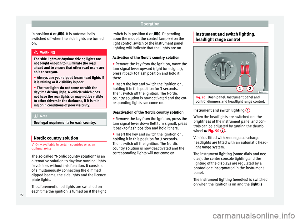
Fig. 90
Dash panel: Instrument panel and
control dimmers and headlight range control. Instrument and switch lighting
1 When the headlights are switched on, the
brightness of the instrument panel and con-
trols can be adjusted by turning the thumb
wheel
››› Fig. 90 1 .
Vehicles fitted with xenon gas discharge
headlights are fitted with an automatic head-
light range system.
The instrument lighting (some dials and nee-
dles), the centre console lighting and the
lighting of the displays are regulated by a
photodiode incorporated in the instrument
panel.
The instrument lighting (needles) is switched
on when the ignition is on and the light is
92
Page 95 of 240

Lights and visibility
off . The instrument lighting is dimmed auto-
m atic
ally as the daylight starts to fade. It
goes out completely when ambient light is
very low. This function is intended to remind
the driver to switch on the dipped beam
headlights in good time when light condi-
tions become poor.
Headlight range control 2By using the electrical headlight range con-
trol,
2 you can adjust the headlight range to
the load level that is being carried in the ve-
hicle. This way, it is possible to avoid daz-
zling oncoming traffic more than necessary.
At the same time, by using the correct head-
light settings, the driver has the best possi-
ble lighting for the road ahead.
The headlights can only be adjusted when
the dipped beam is switched on. To lower the
beam, turn the thumb wheel down 2 from
the basic setting 0.
D y
namic headlight range control
Vehicles with gas discharge bulbs (xenon
bulbs)
are equipped with dynamic headlight
range control. When you switch on the lights,
their range regulates itself according to the
vehicle load.
Vehicles with gas discharge bulbs do not
have headlight range control. Turn signal and main beam headlight
lever
Fig. 91
Turn signal and main beam lever Read the additional information carefully
››› page 14
Signalling a lane change
– Push the lever up 1 or down
2 to the
point where you incur resistance and then
release it. The turn signal will flash several
times. The corresponding control lamp will
also flash.
Switching on parking lights – Switch the ignition off and remove the key
from the lock.
– Move the turn signal lever up or down to
turn the right or left-hand parking lights on,
respectively. WARNING
The main beam can dazzle other drivers. Risk
of accident! Never use the main beam head-
lights or the headlight flasher if they could
dazzle other drivers. Note
● The turn signals only
work when the igni-
tion is switched on. The corresponding warn-
ing lamp or flashes in the instrument
panel
. The control lamp flashes when the
turn signals are operated, provided a trailer is
correctly attached and connected to the vehi-
cle. If a turn signal bulb is defective, the con-
trol lamp flashes at double speed. If the trail-
er turn signal bulbs are defective, the control
lamp does not light up. Change the bulb.
● The main beam headlights
can only be
switched on if the dipped beam headlights
are already on. The warning lamp then
comes on in the instrument panel.
● The headlight flasher come
s on for as long
as you pull the lever – even if no other lights
are switched on. The warning lamp then
comes on in the instrument panel.
● When the parking lights are switched on,
the he
adlight and the tail light on the corre-
sponding side of the vehicle light up. The
parking lights will only work if the key is re-
moved from the ignition. If said light is on, an
audible warning will be emitted while the
driver door is open. » 93
Technical specifications
Advice
Operation
Safety
The essentials
Page 97 of 240

Lights and visibility
When driving around bends, the headlights
will light the most important areas of the
road.
This cornering light gives better illumination
of the side of the road and the corner area.
The dynamic lighting is controlled automati-
cally according to speed and the steering
wheel angle.
The two main headlights move at different
angles to avoid that the front of the vehicle is
left completely in the dark. Note
The system operates from a speed of about
10 km/h (6 mph). Fog lights with cornering function*
This is an additional light source to dipped
beam headlights to light up the road as a
bend is taken.
The cornering light operates with the lights
switched on and when driving at less than
40 Km/h (25 mph). Ignition occurs by turning
the steering or connecting the turn signal.
Forward gear
● If the steering wheel is turned to the right,
or the right-hand turn signal operated, the
right-hand fog light turns on. ●
If the steering wheel is turned to the left, or
the left-hand turn signal operated, the left-
hand fog light turns on.
In reverse, both fog lights turn on. Note
When the fog lamps are on, the cornering
function is activated and both headlights are
continuously on. Hazard warning lights
Read the additional information carefully
››› page 15
The hazard warning lights are used to draw
the attention of other road users to your vehi-
cle in emergencies.
If your vehicle breaks down:
1. Park your vehicle at a safe distance from moving traffic.
2. Press the button to switch on the hazard warning lights ››› .
3. Switch the ignition off.
4. Apply the handbrake.
5. For a manual gearbox, engage 1st gear; for an automatic gearbox, move the gear
lever to P
. 6. Use the warning triangle to draw the atten-
tion of other road users to your vehicle.
7. Always take the vehicle key with you when you leave the vehicle.
All turn signals flash simultaneously when
the hazard warning lights are switched on.
The two turn signal turn signal lamps
and the t
urn signal lamp in the switch will
flash at the same time. The hazard warning
lights also work when the ignition is switch-
ed off. WARNING
● The risk of an accident increases if your ve-
hicle breaks down. Always use the hazard
warning lights and a warning triangle to draw
the attention of other road users to your sta-
tionary vehicle.
● Due to the high temperatures that the cata-
lytic converter can reach, never park in an
area where the catalytic converter could come
into contact with highly inflammable materi-
als, for example dry grass or spilt petrol. This
could start a fire. Note
● The battery will run down if the hazard
warning lights are left on for a long time,
even if the ignition is switched off.
● The use of the hazard warning lights de-
scribed here is subject to the relevant statu-
tory requirements. 95
Technical specifications
Advice
Operation
Safety
The essentials
Page 100 of 240

Operation
again, you have to turn the ignition off and
then on again.
● Do not put stickers on the windscreen in
front of the rain sensor*. This may cause sen-
sor disruption or faults. Rear window wiper
Fig. 96
Windscreen wiper lever: rear window
wiper. Switching on the interval wipe
– Press the lever forward to position 6›››
Fig. 96 . The wiper will wipe the window
ap pr
oximately every 6 seconds.
Switching off the interval wipe function
– Pull the lever back from position 6 toward
the steering wheel. The wiper will continue
to function for a short period if you switch
off whilst the wipers are in motion. Switching on the window wiper and washer
system
– Press the lever fully forwards to position 7 ›››
Fig. 96 . The wiper and washer operate at
the s ame time.
The rear window wash sys-
tem will function as long as you hold the
lever in this position.
– Release the lever. The washer system stops
and the wipers continue until the end of
the cycle.
– Move the lever towards the steering wheel
to switch off. WARNING
● Worn and dirty wiper blades reduce visibili-
ty and safety levels while driving.
● Always note the corresponding warnings
››› page 193. CAUTION
In icy conditions, always check that the wiper
blade is not frozen to the glass before using
the wiper for the first time. If you switch on
the wiper when the wiper blade is frozen to
the glass, this could damage both the wiper
blade and the wiper motor. Note
● The rear window wiper will only work when
the ignition is switched on. ●
Depending on the version of the model,
when you engage reverse gear and with the
headlight wiper activated, this can start a
wipe. Headlight washer*
The headlight washers clean the headlight
lenses.
The headlight washers are activated auto-
matically when the windscreen washer is
used and the window wiper lever is pulled to-
wards the steering wheel for at least 1.5 sec-
onds – provided the dipped beam headlights
or main beams are switched on. Clean off
stubborn dirt (insects, etc.) from the head-
lights at regular intervals, for instance when
filling the fuel tank.
Note
● To ensure that the headlight washers work
properly in winter, keep the nozzle holders in
the bumper free of snow and remove any ice
with a de-icer spray.
● To remove water, the windscreen wipers
will be activated from time to time, the head-
light washers will be activated every three cy-
cles. 98
Page 114 of 240
Operation
Securing the crossbars and the roof
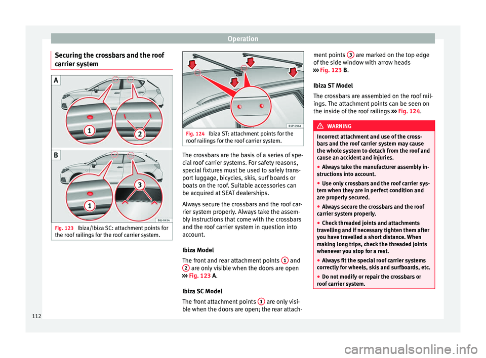
carrier system Fig. 123
Ibiza/Ibiza SC: attachment points for
the roof railings for the roof carrier system. Fig. 124
Ibiza ST: attachment points for the
roof railings for the roof carrier system. The crossbars are the basis of a series of spe-
cial roof carrier systems. For safety reasons,
special fixtures must be used to safely trans-
port luggage, bicycles, skis, surf boards or
boats on the roof. Suitable accessories can
be acquired at SEAT dealerships.
Always secure the crossbars and the roof car-
rier system properly. Always take the assem-
bly instructions that come with the crossbars
and the roof carrier system in question into
account.
Ibiza Model
The front and rear attachment points
1 and
2 are only visible when the doors are open
››› Fig. 123
A.
Ibiza SC Model
The front attachment points 1 are only visi-
ble when the doors are open; the rear attach- ment points
3 are marked on the top edge
of the side window with arrow heads
››› Fig. 123
B
.
Ibiza ST Model
The crossbars are assembled on the roof rail-
ings. The attachment points can be seen on
the inside of the roof railings ››› Fig. 124
. WARNING
Incorrect attachment and use of the cross-
bars and the roof carrier system may cause
the whole system to detach from the roof and
cause an accident and injuries.
● Always take the manufacturer assembly in-
structions into account.
● Use only crossbars and the roof carrier sys-
tem when they are in perfect condition and
are properly secured.
● Always secure the crossbars and the roof
carrier system properly.
● Check threaded joints and attachments
travelling and if necessary tighten them after
you have travelled a short distance. When
making long trips, check the threaded joints
whenever you stop for a rest.
● Always fit the special roof carrier systems
correctly for wheels, skis and surfboards, etc.
● Do not modify or repair the crossbars or
roof carrier system. 112
Page 125 of 240

Driving
When the outside temperature is low, air re-
circulation mode improves heating perform-
ance by heating air from the interior instead
of cold air from the outside.
When the outside temperature is high, air re-
circulation mode improves cooling perform-
ance by cooling air from the interior instead
of warm air from outside.
For safety reasons, the air recirculation
should not be switched on when the air dis-
tribution control is set to the windscreen set-
ting . WARNING
In air recirculation mode, no cold air from the
outside enters the vehicle interior. If the air
conditioner is switched off, the windows can
quickly mist over. Therefore, never leave the
air recirculation mode switched on for a long
time (risk of accident). Note
When engaging reverse gear, the air recircu-
lation is connected automatically to prevent
the entrance of exhaust gases into the vehi-
cle upon travelling backwards. In this case
the symbol for air recirculation is not dis-
played. Driving
Starting and stopping the
engine Ignition key positions Fig. 131
Ignition key positions. Ignition switched off, steering lock
1 In this position
››› Fig. 131, the ignition and
the engine are OFF and the steering may be
locked.
For the Steering lock
to operate without the
ignition k
ey, turn the steering wheel until it
locks with an audible sound. You should al-
ways lock the steering wheel when you leave
your vehicle. This will help prevent vehicle
theft ››› .Switching the ignition or the glow plug
system on
2 Turn the ignition key to this position and re-
lease it. If the key cannot be turned or it is
difficult to turn from position
1 to position
2 , move the steering wheel from one side to
the other; this will release it.
Starting 3 The engine is started when the key is in this
position. Electrical devices with high power
consumption are switched off temporarily at
the same time.
Each time that the vehicle is restarted, the ig-
nition key must be turned to position
1 . The
repetitive start prevention lock of the igni-
tion prevents possible damage to the starter
motor if the engine is already running. WARNING
● The ignition key must NOT be removed from
the lock until the vehicle comes to a stand-
still. Otherwise, the steering could be imme-
diately blocked- Risk of accident!
● Always remove the key from the ignition
when leaving the vehicle, even if only for a
short period. This is especially important if
children or disabled people are left alone in
the vehicle. They could accidentally start the
engine or work electrical equipment such as
the electric windows, resulting in an acci-
dent. » 123
Technical specifications
Advice
Operation
Safety
The essentials