2014 Seat Ibiza 5D wheel
[x] Cancel search: wheelPage 186 of 240

Advice
Removing
– Remove the wheel cover using the wire
hook ››› Fig. 158 .
– Hook thi
s into one of the cut-outs of the
wheel cover.
Fitting
– Fit the wheel cover onto the wheel rim by
pressing it firmly. Put pressure initially on
the point of the cut-out for the valve. Next
fit the rest of the hubcap
Loosening the wheel bolts Fig. 159
Changing a wheel: loosen the wheel
bolts. The wheel bolts must be loosened before
raising the vehicle. Loosening
– Fit the box spanner as far as it will go over
the wheel bolt.
– Grasp the box spanner by the end turn it
about one full turn to the left
›
›› Fig. 159
.
Tightening
– Fit the box spanner as far as it will go over
the wheel bolt.
– Grasp the box spanner close to the end and
turn the bolt to the right until it is secured.
– An adapter is required to unscrew or tight-
en the anti-theft wheel bolts. WARNING
Loosen the wheel bolts (only about one turn)
before raising the vehicle with the jack, oth-
erwise there is a risk of accident. Note
● If the wheel bolt is very tight, you may be
able to loosen it by pushing the end of the
spanner down carefully with your foot. Hold
on to the vehicle for support and take care
not to slip. Raising the vehicle
Fig. 160
Jack position points Fig. 161
Fitting the jack. Read the additional information carefully
››› page 27
In order to remove the wheel, the vehicle
must be raised with a jack.
– Locate the jacking point under the door sill
closest to the punctured wheel ››› Fig. 160 .
184
Page 187 of 240

Emergencies
– Place the jack under the jacking point and
turn the crank until the arm of the jack is di-
rectly below the vertical rib under the door
sill.
– Align the jack so that the arm of the jack
fits around the rib under the door sill and
the movable base plate of the jack is flat on
the ground ››› Fig. 161 .
– Rai
se the vehicle until the defective wheel
is just clear of the ground.
Recesses at the front and rear of the door
sills mark the jacking points ››› Fig. 160.
There i
s only one jacking point for each
wheel. Do not fit the jack anywhere else.
An
unstable surface under the jack may
cause the vehicle to slip off the jack. There-
fore, it must be fitted on solid ground offer-
ing good support. Use a large and stable
base, if necessary. On a hard, slippery sur-
face (such as tile) use a rubber mat or similar
to prevent the jack from slipping. WARNING
● Take all precautions so that the base of the
jack does not slip. Failure to follow this in-
struction could result in an accident.
● The vehicle can be damaged if the jack is
not applied at the correct jacking points.
There is also a risk of injury since the jack can
slip off suddenly if it is not properly engaged. Removing and fitting the wheel
Change the wheel as described below after
loosening the wheel bolts and raising the ve-
hicle with the jack.
Removing a wheel
– Unscrew the wheel bolts using the box
spanner and place them on a clean surface.
Fitting a wheel
– Screw on the wheel bolts in position and
tighten them loosely with a box spanner.
The wheel bolts should be clean and easily
screwed. Before fitting the spare wheel, in-
spect the wheel condition and hub mounting
surfaces. These surfaces must be clean be-
fore fitting the wheel.
If tyres with a specific direction of rotation
are fitted, note the direction of rotation. Anti-theft wheel bolts* Fig. 162
Anti-theft wheel bolt with cap and
adapter. A special adapter is required to turn the anti-
theft wheel bolts. This is found in the tool
box.
– Insert the adapter onto the wheel bolt and
push it on as far as it will go ››› Fig. 162 .
– Fit the bo
x spanner as far as it will go over
the adapter.
– Loosen or tighten the wheel bolt as appro-
priate.
Code
The code number of the anti-theft wheel bolt
is stamped onto the front part of the adaptor.
The code number should be noted and kept
in a safe place, as it is only by using the code
number that a duplicate adaptor can be ob-
tained from SEAT Official Services. 185
Technical specifications
Advice
Operation
Safety
The essentials
Page 188 of 240

Advice
Tyres with directional tread pattern A directional tread pattern can be identified
by arrows on the sidewall that point in the di-
rection of rotation. Always note the direction
of rotation indicated when fitting the wheel.
This is important so that these tyres can give
maximum grip and avoid excessive noise,
tread wear and aquaplaning.
If, in an emergency, you have to mount the
spare wheel so it rotates in the wrong direc-
tion, you must drive extremely carefully. The
tyre will not give optimum performance. This
is particularly important when driving on wet
roads.
To benefit from the advantages of tyres with
this type of tread pattern, the defective tyre
should be replaced as soon as possible so
that all tyres again rotate in the correct direc-
tion.
Tyre repair TMS (Tyre Mobility System)* Read the additional information carefully
››› page 26
The Anti-puncture kit* (Tyre Mobility System)
will reliably seal punctures caused by the
penetration of a foreign body of up to about 4 mm in diameter. Do not remove foreign ob-
jects, e.g. screws or nails, from the tyre.
After inserting the sealant residue in the tyre,
you must again check the tyre pressure about
10 minutes after starting the engine.
You should only use the tire mobility set if
the vehicle is parked in a safe place, you are
familiar with the procedure and you have the
necessary tire mobility set! Otherwise, you
should seek professional assistance.
The tyre sealant must not be used in the
following cases:
● If the wheel rim has been damaged.
● In outside temperatures below -20 °C
(-4 °F).
● In the event of cuts or perforations in the
tyre greater than 4 mm.
● If you have been driving with very low pres-
sure or a completely flat tyre.
● If the sealant bottle has passed its use by
date. WARNING
Using the tyre mobility system can be dan-
gerous, especially when filling the tyre at the
roadside. Please observe the following rules
to minimise the risk of injury:
● Stop the vehicle safely as soon as possible.
Park it at a safe distance from surrounding
traffic to fill the tyre. ●
Ensure the ground on which you park is flat
and solid.
● All passengers and particularly children
must keep a safe distance from the work area.
● Turn on the hazard warning lights to warn
other road users.
● Use the tyre mobility system only if you are
familiar with the necessary procedures. Oth-
erwise, you should seek professional assis-
tance.
● The tyre mobility set is intended for tempo-
rary emergency use only until you can reach
the nearest specialised workshop.
● Replace the repaired tyre with the tire mo-
bility set as soon as possible.
● The sealant is a health hazard and must be
cleaned immediately if it comes into contact
with the skin.
● Always keep the tire mobility set out of the
reach of small children.
● Never use an equivalent jack, even if it has
been approved for your vehicle.
● Always stop the engine, apply the hand-
brake lever firmly and engage gear if using a
manual gearbox, in order to reduce the risk of
vehicle involuntary movement. WARNING
A tyre filled with sealant does not have the
same performance properties as a conven-
tional tyre.
● Never drive faster than 80 km/h (50 mph). 186
Page 189 of 240

Emergencies
●
Avoid heavy acceleration, hard braking and
fast cornering.
● Drive for only 10 minutes at a maximum
speed of 80 km/h (50 mph) and then check
the tyre. For the sake of the environment
Dispose of used or expired sealant observing
any legal requirements. Note
● A new bottle of sealant can be purchased at
SEAT dealerships.
● Take into account the separate instruction
manual of the tyre mobility set* manufactur-
er. Contents of the tyre mobility system*
Fig. 163
Standard representation: Contents
of the tyre mobility system. The tyre mobility set is located underneath
the floor covering in the luggage compart-
ment. It includes the following components
››› Fig. 163 :
T y
re valve remover
Sticker indicating maximum speed “max.
80 km/h” or “max. 50 mph”
Filler tube with cap
Air compressor
Tube for inflating tyres
Warning provided by tyre pressure moni-
toring system (it can also be integrated in
the compressor).
1 2
3
4
5
6 Air bleed screw (in its place, the compres-
sor may have a button).
ON/OFF switch
12 volt connector
Bottle of sealant
Spare tyre valve
The valve insert remover
1 has a gap at the
lower end for a valve insert. The valve insert
can only be screwed or unscrewed in this
way. This also applies to its replacement part 11 .
WARNING
When inflating the wheel, the air compressor
and the inflator tube may become hot.
● Protect hands and skin from hot parts.
● Do not place the hot flexible inflator tube or
hot air compressor on flammable material.
● Allow them to cool before storing the de-
vice.
● If it is not possible to inflate the tyre to at
least 2.0 bars (29 psi / 200 kPa), the tyre is
too badly damaged. The sealant is not in a
good condition to seal the tyre. Do not con-
tinue driving. Seek specialist assistance. CAUTION
Switch off the air compressor after a maxi-
mum of 8 operational minutes to avoid over-
heating! Before switching on the air compres-
sor again, let it cool for several minutes. 7
8
9
10
11
187
Technical specifications
Advice
Operation
Safety
The essentials
Page 192 of 240
Advice
Note
The vehicles must not touch each other, oth-
erwise electricity could flow as soon as the
positive terminals are connected. Towing or tow starting
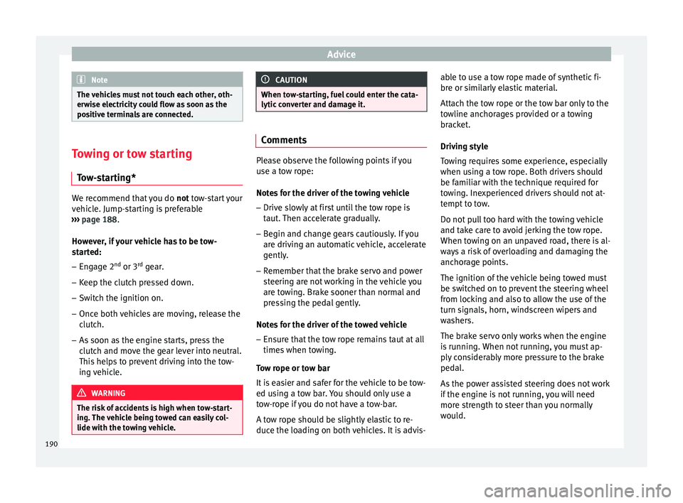
Tow-starting* We recommend that you do
not tow-start your
v ehic
le. Jump-starting is preferable
››› page 188.
Ho w
ever, if your vehicle has to be tow-
started:
– Engage 2 nd
or 3 rd
gear.
– Keep the clutch pressed down.
– Switch the ignition on.
– Once both vehicles are moving, release the
clutch.
– As soon as the engine starts, press the
clutch and move the gear lever into neutral.
This helps to prevent driving into the tow-
ing vehicle. WARNING
The risk of accidents is high when tow-start-
ing. The vehicle being towed can easily col-
lide with the towing vehicle. CAUTION
When tow-starting, fuel could enter the cata-
lytic converter and damage it. Comments
Please observe the following points if you
use a tow rope:
Notes for the driver of the towing vehicle
– Drive slowly at first until the tow rope is
taut. Then accelerate gradually.
– Begin and change gears cautiously. If you
are driving an automatic vehicle, accelerate
gently.
– Remember that the brake servo and power
steering are not working in the vehicle you
are towing. Brake sooner than normal and
pressing the pedal gently.
Notes for the driver of the towed vehicle
– Ensure that the tow rope remains taut at all
times when towing.
Tow rope or tow bar
It is easier and safer for the vehicle to be tow-
ed using a tow bar. You should only use a
tow-rope if you do not have a tow-bar.
A tow rope should be slightly elastic to re-
duce the loading on both vehicles. It is advis- able to use a tow rope made of synthetic fi-
bre or similarly elastic material.
Attach the tow rope or the tow bar only to the
towline anchorages provided or a towing
bracket.
Driving style
Towing requires some experience, especially
when using a tow rope. Both drivers should
be familiar with the technique required for
towing. Inexperienced drivers should not at-
tempt to tow.
Do not pull too hard with the towing vehicle
and take care to avoid jerking the tow rope.
When towing on an unpaved road, there is al-
ways a risk of overloading and damaging the
anchorage points.
The ignition of the vehicle being towed must
be switched on to prevent the steering wheel
from locking and also to allow the use of the
turn signals, horn, windscreen wipers and
washers.
The brake servo only works when the engine
is running. When not running, you must ap-
ply considerably more pressure to the brake
pedal.
As the power assisted steering does not work
if the engine is not running, you will need
more strength to steer than you normally
would.
190
Page 193 of 240

Emergencies
Towing vehicles with an automatic gearbox
● Put the selector lever into position “N”.
● Do not drive faster than 50 km/h (31 mph).
● Do not tow further than 50 km.
● If a breakdown vehicle is used, the vehicle
must be towed with the front wheels raised. Note
● Observe legal requirements when towing or
tow-starting.
● Switch on the hazard warning lights of both
vehicles. However, observe any regulations
to the contrary.
● For technical reasons, vehicles with an au-
tomatic gearbox must not be tow-started.
● If there is no lubricant in the gearbox as the
result of a fault, you must raise the driven
wheels while the vehicle is being towed.
● If the vehicle has to be towed more than
50 km (30 miles), the front wheels should be
raised during towing, and towing should be
carried out by a qualified person.
● The steering wheel is locked when the vehi-
cle has no electrical power. The vehicle must
then be towed with the front wheels raised.
Towing should be carried out by a qualified
person.
● The towline anchorage should always be
kept in the vehicle. Front towline anchorage
Fig. 166
Towline anchorage at the front of the
vehicle Read the additional information carefully
››› page 28
Fitting the towline anchorage
– Take the towline anchorage from the on-
board tool set.
– Remove the front cover by pressing down
on its left-hand side. For FR finishes, press
down and pull outwards. For the rest of the
Sport finishes, remove the cover by insert-
ing a screwdriver into the lower slot and
levering gently.
– Bolt the anchorage to its limit to the left, in
the dir ection of
the arrow ››› Fig. 166. Rear towline anchorage Read the additional information carefully
››› page 28
There is a towline anchorage at the rear on
the right below the rear bumper.
191
Technical specifications
Advice
Operation
Safety
The essentials
Page 204 of 240
Advice
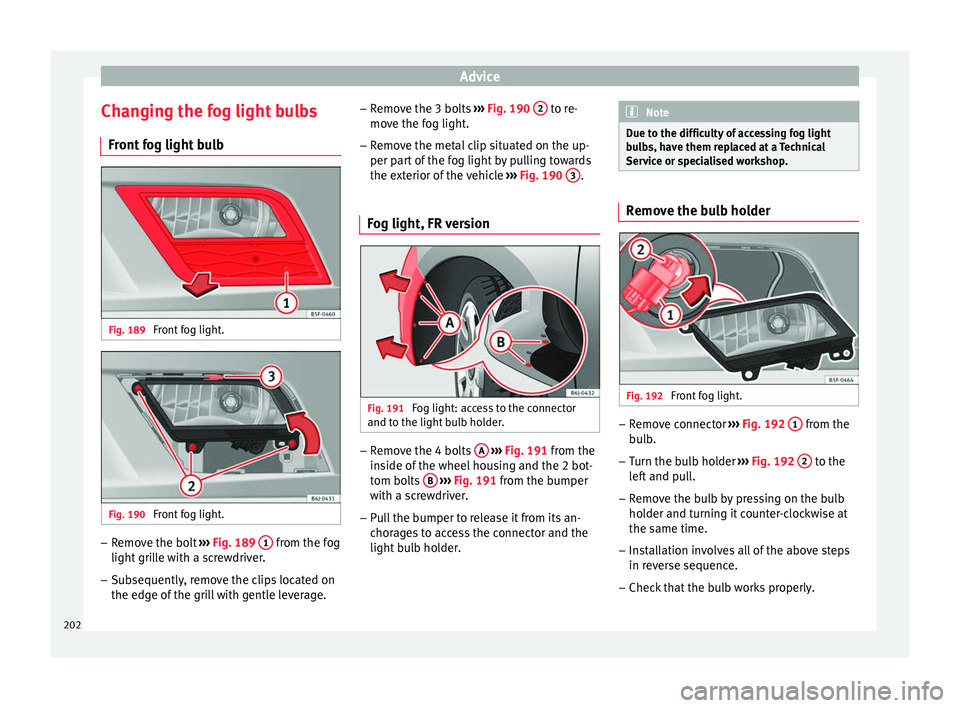
Changing the fog light bulbs Front fog light bulb Fig. 189
Front fog light. Fig. 190
Front fog light. –
Remove the bolt ››› Fig. 189 1 from the fog
light grille with a screwdriver.
– Subsequently, remove the clips located on
the edge of the grill with gentle leverage. –
Remove the 3 bolts ››› Fig. 190 2 to re-
move the fog light.
– Remove the metal clip situated on the up-
per part of the fog light by pulling towards
the exterior of the vehicle ››› Fig. 190 3 .
Fog light, FR version Fig. 191
Fog light: access to the connector
and to the light bulb holder. –
Remove the 4 bolts A
››› Fig. 191 from the
in s
ide of the wheel housing and the 2 bot-
tom bolts B
››› Fig. 191 from the bumper
with a screwdriver.
– Pull the bumper to release it from its an-
chorages to access the connector and the
light bulb holder. Note
Due to the difficulty of accessing fog light
bulbs, have them replaced at a Technical
Service or specialised workshop. Remove the bulb holder
Fig. 192
Front fog light. –
Remove connector ››› Fig. 192 1 from the
bulb.
– Turn the bulb holder ››› Fig. 192 2 to the
left and pull.
– Remove the bulb by pressing on the bulb
holder and turning it counter-clockwise at
the same time.
– Installation involves all of the above steps
in reverse sequence.
– Check that the bulb works properly.
202
Page 211 of 240

Technical features
Vehicles for certain export countries do not
have an identification plate.
Identification plate
The identification plate is located on the right
rib inside the engine compartment.
Vehicle data
The data sticker is placed on the inside of the
spare wheel well, in the boot and on the rear
cover of the Maintenance Programme.
The following information is provided on the
vehicle data sticker: ››› Fig. 207
Vehicle identification number (chassis
number)
Vehicle type, model, capacity, engine
type, finish, engine power and gearbox
type
Engine code, gearbox code, external
paint code and internal equipment code
Optional extras and PR numbers
Consumption values (l/100 km) and CO 2
emissions (g/km)
A Urban cycle consumption
B Out-of-town consumption
C Combined consumption and CO
2
emissions
1 2
3
4
5 Chassis number
The vehicle identification number can be
read from outside the vehicle through a view-
er in the windscreen
››› Fig. 208 . The viewer is
loc at
ed near the lower corner of the wind-
screen. The chassis number is printed on the
right water drain channel. The water drain
channel is located between the suspension
turret and the fender. To access the chassis
number, open the bonnet ››› page 166.
Information on fuel
consumption Fuel consumption and CO 2 emissions The consumption and emission details
shown on the vehicle data sticker differ from
one vehicle to another.
Vehicle fuel consumption and CO
2 emissions
appear on the vehicle data sticker in the
spare wheel well, inside the boot and on the
rear cover of the Maintenance Programme.
The fuel consumption and CO 2 emission val-
ues refer to the weight category assigned to
your vehicle according to the engine and
gearbox combination, as well as the specific
equipment fitted, and is only used to com-
pare between the different models. The fuel consumption and CO
2 emissions do
not depend only on the performance of the
vehicle, they can also differ from the estab-
lished values depending on other factors
such as driving style, road conditions, traffic
conditions, environmental conditions, load
and number of passengers.
Calculation of fuel consumption
The consumption values have been calcula-
ted based on measurements performed or
supervised by certified CE laboratories ac-
cording to the latest version of directives
715/2007/EC and 80/1268/CEE (for more in-
formation consult the European Union Publi-
cations Office at EUR-Lex: © European Union,
http://eur-lex.europa.eu/en/index.htm) and
are valid for the kerb weight indicated for the
vehicle. Note
In practice, and considering all the factors
mentioned here, consumption values can dif-
fer from those calculated in the current Euro-
pean regulations. Weights
Kerb weight refers to the basic model with a
fuel tank filled to 90% capacity and without
optional extras. The figure quoted includes
75 kg to allow for the weight of the driver.
»
209
Technical specifications
Advice
Operation
Safety
The essentials