2014 NISSAN TEANA horn
[x] Cancel search: hornPage 3976 of 4801

SR-14
< REMOVAL AND INSTALLATION >
DRIVER AIR BAG MODULE
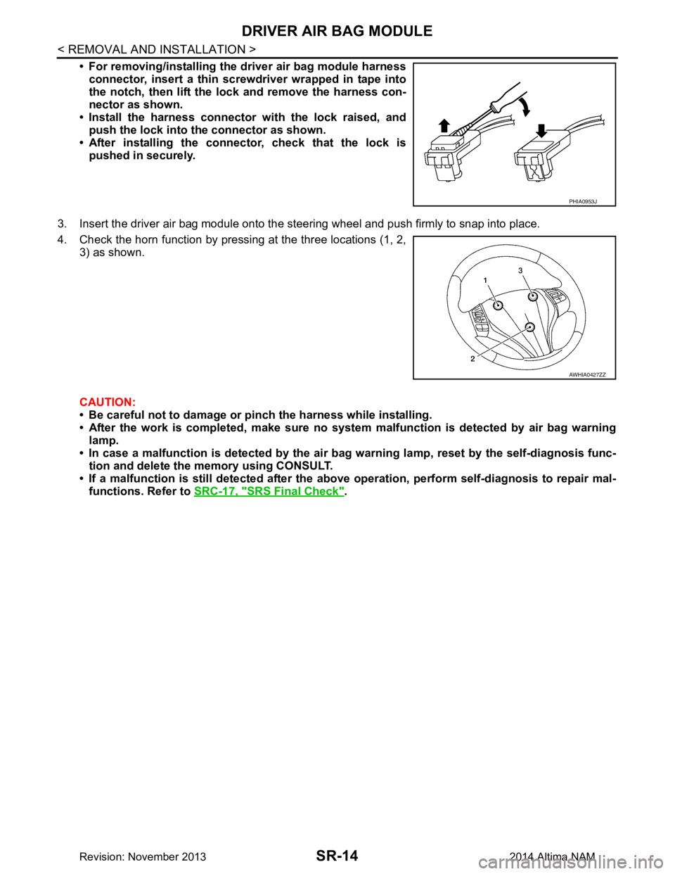
• For removing/installing the driver air bag module harnessconnector, insert a thin screwdriver wrapped in tape into
the notch, then lift the lock and remove the harness con-
nector as shown.
• Install the harness connector with the lock raised, and push the lock into the connector as shown.
• After installing the conn ector, check that the lock is
pushed in securely.
3. Insert the driver air bag module onto the st eering wheel and push firmly to snap into place.
4. Check the horn function by pressing at the three locations (1, 2, 3) as shown.
CAUTION:
• Be careful not to damage or pinch the harness while installing.
• After the work is completed, make sure no syst em malfunction is detected by air bag warning
lamp.
• In case a malfunction is detected by the air bag warning lamp, reset by the self-diagnosis func-
tion and delete the memory using CONSULT.
• If a malfunction is still detected after the abo ve operation, perform self-diagnosis to repair mal-
functions. Refer to SRC-17, "SRS Final Check"
.
PHIA0953J
AWHIA0427ZZ
Revision: November 20132014 Altima NAM
Page 4684 of 4801

SYSTEMWT-9
< SYSTEM DESCRIPTION >
C
D
F
G H
I
J
K L
M A
B
WT
N
O P
System DescriptionINFOID:0000000009464484
When the vehicle has reached a speed of 40 km/h (25 MPH) or greater, the BCM receives a signal transmitted
from the tire pressure sensors/transmitters installed in each wheel. If the BCM detects low inflation pressure or
a system malfunction, it sends a signal to the combi nation meter via CAN communication to illuminate the low
tire pressure warning lamp. In addition, a warning message will be displayed in the vehicle information display.
Refer to the Owner’s Manual for additional information.
The tire pressure monitoring system (TPMS) has Easy fill ti re alert function to aid in tire inflation. Refer to WT-
9, "Easy Fill Tire Alert Function".
Low Tire Pressure Warning Lamp and Display Indications
Easy Fill Tire Alert FunctionINFOID:0000000009464485
NOTE:
When beginning tire inflation, it takes a few seconds for t he Easy fill tire alert to function. If there is no
response for approximately 15 seconds or more, cancel t he Easy fill tire alert function and move the vehicle
approximately 1 m (3.2 ft) backward or forward to try again.
• The Easy fill tire alert function operates only when t he select lever position is in P-range with the ignition
switch ON.
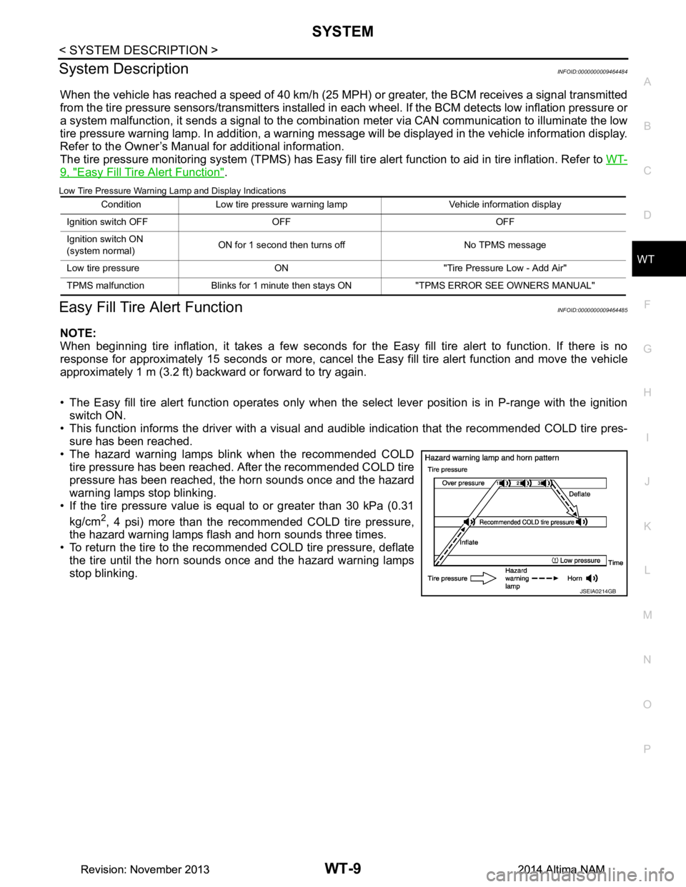
• This function informs the driver with a visual and audible indication that the recommended COLD tire pres-
sure has been reached.
• The hazard warning lamps blink when the recommended COLD tire pressure has been reached. After the recommended COLD tire
pressure has been reached, the horn sounds once and the hazard
warning lamps stop blinking.
• If the tire pressure value is equal to or greater than 30 kPa (0.31
kg/cm
2, 4 psi) more than the recommended COLD tire pressure,
the hazard warning lamps flash and horn sounds three times.
• To return the tire to the recommended COLD tire pressure, deflate
the tire until the horn sounds once and the hazard warning lamps
stop blinking.
Condition Low tire pressure warning lamp Vehicle information display
Ignition switch OFF OFF OFF
Ignition switch ON
(system normal) ON for 1 second then turns off No TPMS message
Low tire pressure ON "Tire Pressure Low - Add Air"
TPMS malfunction Blinks for 1 minute th en stays ON "TPMS ERROR SEE OWNERS MANUAL"
JSEIA0214GB
Revision: November 20132014 Altima NAMRevision: November 20132014 Altima NAM
Page 4686 of 4801

DIAGNOSIS SYSTEM (BCM)WT-11
< SYSTEM DESCRIPTION >
C
D
F
G H
I
J
K L
M A
B
WT
N
O PAIR PRESSURE MONITOR
AIR PRESSURE MONITOR : CONSULT Fu nction (BCM-AIR PRESSURE MONITOR)
INFOID:0000000009955586
CAUTION:
After disconnecting the CONSULT vehicle interface (VI) from the data link connector, the ignition must
be cycled OFF → ON (for at least 5 seconds) → OFF. If this step is not performed, the BCM may not go
to ”sleep mode”, potentiall y causing a discharged battery and a no-start condition.
NOTE:
The Signal Tech II Tool (J-50190) can be used to perform the following functions. Refer to the Signal Tech II
User Guide for additional information.
• Activate and display TPMS transmitter IDs
• Display tire pressure repor ted by the TPMS transmitter
• Read TPMS DTCs
• Register TPMS transmitter IDs
SELF DIAGNOSTIC RESULT
NOTE:
Before performing Self Diagnostic Result, be sure to regi ster the transmitter ID or the actual malfunction may
be different from that displayed on CONSULT.
Refer to BCS-52, "DTC Index"
.
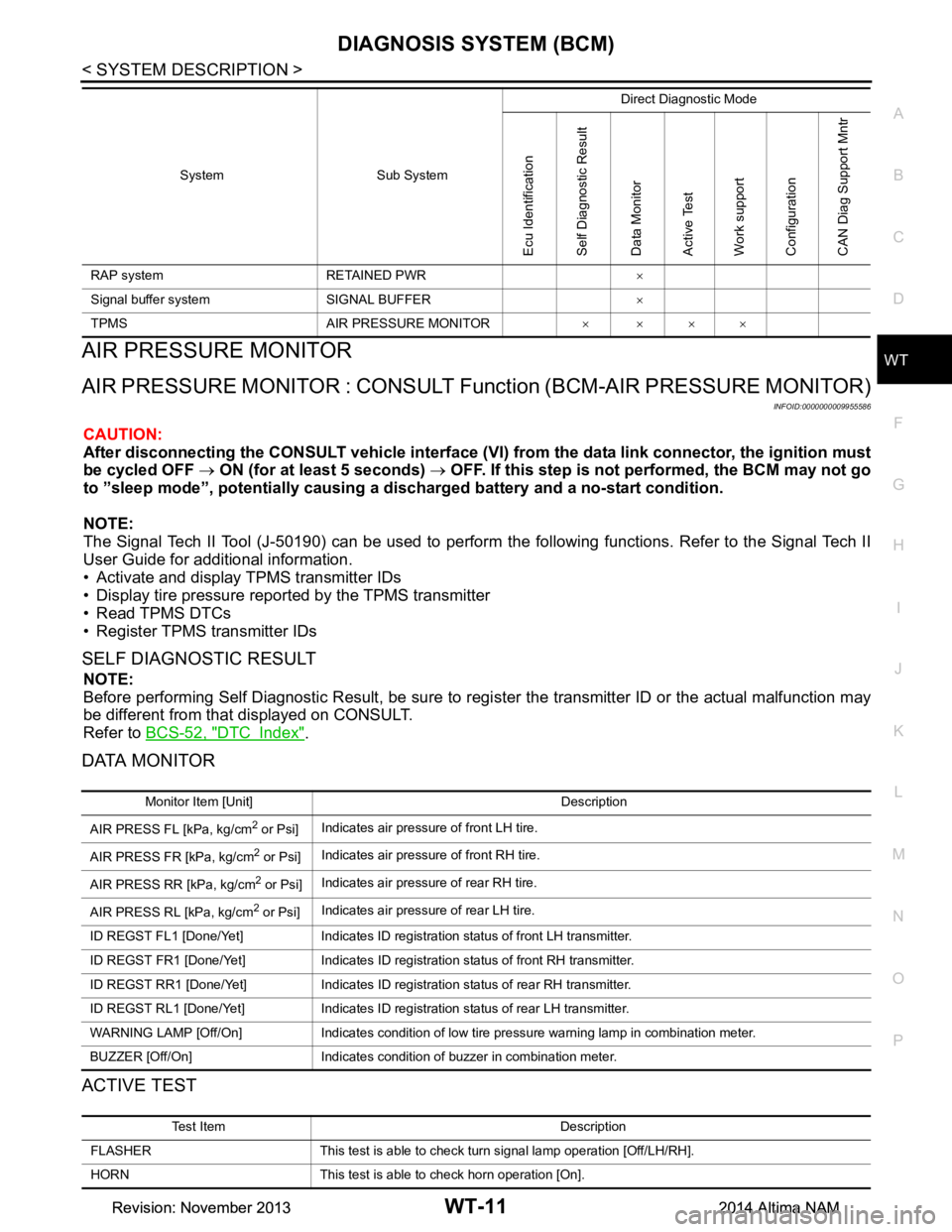
DATA MONITOR
ACTIVE TEST
RAP system RETAINED PWR ×
Signal buffer system SIGNAL BUFFER ×
TPMS AIR PRESSURE MONITOR ××××
System Sub System
Direct Diagnostic Mode
Ecu Identification
Self Diagnostic Result
Data Monitor
Active Test
Work support
Configuration
CAN Diag Support Mntr
Monitor Item [Unit] Description
AIR PRESS FL [kPa, kg/cm
2 or Psi] Indicates air pressure of front LH tire.
AIR PRESS FR [kPa, kg/cm
2 or Psi] Indicates air pressure of front RH tire.
AIR PRESS RR [kPa, kg/cm
2 or Psi] Indicates air pressure of rear RH tire.
AIR PRESS RL [kPa, kg/cm
2 or Psi] Indicates air pressure of rear LH tire.
ID REGST FL1 [Done/Yet] Indicates ID registration status of front LH transmitter.
ID REGST FR1 [Done/Yet] Indicates ID registration status of front RH transmitter.
ID REGST RR1 [Done/Yet] Indicates ID registration status of rear RH transmitter.
ID REGST RL1 [Done/Yet] Indicates ID registration status of rear LH transmitter.
WARNING LAMP [Off/On] Indicates condition of low tire pressure warning lamp in combination meter.
BUZZER [Off/On] Indicates condition of buzzer in combination meter.
Test Item Description
FLASHER This test is able to check turn signal lamp operation [Off/LH/RH].
HORN This test is able to check horn operation [On].
Revision: November 20132014 Altima NAMRevision: November 20132014 Altima NAM
Page 4726 of 4801

EASY FILL TIRE ALERT DOES NOT ACTIVATEWT-51
< SYMPTOM DIAGNOSIS >
C
D
F
G H
I
J
K L
M A
B
WT
N
O P
EASY FILL TIRE ALERT DOES NOT ACTIVATE
DescriptionINFOID:0000000009464517
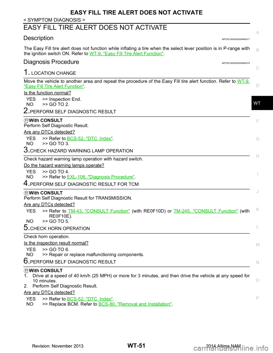
The Easy Fill tire alert does not function while inflating a tire when the select lever position is in P-range with
the ignition switch ON. Refer to WT-9, "Easy Fill Tire Alert Function"
.
Diagnosis ProcedureINFOID:0000000009464518
1. LOCATION CHANGE
Move the vehicle to another area and repeat the procedure of the Easy Fill tire alert function. Refer to WT-9,
"Easy Fill Tire Alert Function".
Is the function normal?
YES >> Inspection End.
NO >> GO TO 2.
2.PERFORM SELF DIAGNOSTIC RESULT
With CONSULT
Perform Self Diagnostic Result.
Are any DTCs detected?
YES >> Refer to BCS-52, "DTC Index".
NO >> GO TO 3.
3.CHECK HAZARD WARNING LAMP OPERATION
Check hazard warning lamp operation with hazard switch.
Do the hazard warning lamps operate?
YES >> GO TO 4.
NO >> Refer to EXL-106, "Diagnosis Procedure"
.
4.PERFORM SELF DIAGNOSTIC RESULT FOR TCM
With CONSULT
Perform Self Diagnostic Result for TRANSMISSION.
Are any DTCs detected?
YES >> Refer to TM-43, "CONSULT Function" (with RE0F10D) or TM-245, "CONSULT Function" (with
RE0F10E).
NO >> GO TO 5.
5.CHECK HORN OPERATION
Check horn operation.
Is the inspection result normal?
YES >> GO TO 6.
NO >> Repair or replace malfunctioning components.
6.PERFORM SELF DIAGNOSTIC RESULT
With CONSULT
1. Drive at a speed of 40 km/h (25 MPH) or more fo r 3 minutes, and then drive the vehicle at any speed for
10 minutes.
2. Perform Self Diagnostic Result.
Are any DTCs detected?
YES >> Refer to BCS-52, "DTC Index".
NO >> Replace BCM. Refer to BCS-80, "Removal and Installation"
.
Revision: November 20132014 Altima NAMRevision: November 20132014 Altima NAM
Page 4747 of 4801

WW-12
< SYSTEM DESCRIPTION >
DIAGNOSIS SYSTEM (IPDM E/R)
DIAGNOSIS SYSTEM (IPDM E/R)
Diagnosis DescriptionINFOID:0000000009944155
AUTO ACTIVE TEST
Description
In auto active test mode, the IPDM E/R sends a drive signal to the follo wing systems to check their operation.
• Front wiper (LO, HI)
• Front fog lamps
• Parking lamps
• Side marker lamps
• Tail lamps
• License plate lamps
• Daytime running lamps
• Headlamps (LO, HI)
• A/C compressor
• Cooling fans (LO, HI)
Operation Procedure
CAUTION:
Do not start the engine.
NOTE:
When auto active test is performed with hood opened, sprinkle water on windshield before hand.
NOTE:
• If auto active test mode cannot be actuat ed, check door switch system. Refer to DLK-100,
"Component Function Check".
• When auto active test mode has to be cancelled halfway through test, turn ignition switch OFF.
1. Close the hood and lift the wiper arms from the windshield. (Prevent windshield damage due to wiper
operation)
2. Turn ignition switch OFF.
3. Turn the ignition switch ON, and within 20 seconds, press the front door switch LH 10 times. Then turn the ignition switch OFF.
4. Turn the ignition switch ON within 10 seconds. Af ter that the horn sounds once, and the auto active test
starts.
5. After a series of the following operations is repeated 3 times, auto active test is completed.
Inspection in Auto Active Test Mode
When auto active test mode is actuated, the following operation sequence is repeated 3 times.
*: Outputs duty ratio of 50% for 5 seconds → duty ratio of 100% for 5 seconds on the cooling fan control module.
Operation se-
quence Inspection Location Operation
1 Front wiper LO for 3 seconds → HI for 3 seconds
2 •Front fog lamps
• Parking lamps
• Side marker lamps
•Tail lamps
• License plate lamps 10 seconds
3 Daytime running lamps 10 seconds
4 Headlamps LO ⇔ HI 5 times
5 A/C compressor ON ⇔ OFF 5 times
6
*Cooling fans LO for 5 seconds → HI for 5 seconds
Revision: November 20132014 Altima NAMRevision: November 20132014 Altima NAM
Page 4749 of 4801

WW-14
< SYSTEM DESCRIPTION >
DIAGNOSIS SYSTEM (IPDM E/R)
APPLICATION ITEM
CONSULT performs the following functions via CAN communication with IPDM E/R.
ECU IDENTIFICATION
The IPDM E/R part number is displayed.
SELF DIAGNOSTIC RESULT
Refer to PCS-20, "DTC Index".
DATA MONITOR
Direct Diagnostic Mode Description
Ecu Identification The IPDM E/R part number is displayed.
Self Diagnostic Result The IPDM E/R self diagnostic results are displayed.
Data Monitor The IPDM E/R input/output data is displayed in real time.
Active Test The IPDM E/R activates outputs to test components.
CAN Diag Support Mntr The result of transmit/receive diagnosis of CAN communication is displayed.
Monitor Item [Unit] Main
Signals Description
MOTOR FAN REQ [%] ×Indicates cooling fan speed signal received from ECM on CAN communication
line
AC COMP REQ [On/Off] ×Indicates A/C compressor request signal received from ECM on CAN commu-
nication line
TAIL&CLR REQ [On/Off] ×Indicates position light request signal received from BCM on CAN communica-
tion line
HL LO REQ [On/Off] ×Indicates low beam request signal received from BCM on CAN communication
line
HL HI REQ [On/Off] ×Indicates high beam request signal received from BCM on CAN communication
line
FR FOG REQ [On/Off] ×Indicates front fog light request signal received from BCM on CAN communica-
tion line
FR WIP REQ [Stop/1LOW/Low/Hi] ×Indicates front wiper request signal received from BCM on CAN communication
line
WIP AUTO STOP [STOP P/ACT P] ×Indicates condition of front wiper auto stop signal
WIP PROT [Off/BLOCK] ×Indicates condition of front wiper fail-safe operation
IGN RLY1 -REQ [On/Off] Indicates ignition switch ON signal received from BCM on CAN communication
line
IGN RLY [On/Off] ×Indicates condition of ignition relay
PUSH SW [On/Off] Indicates condition of push-button ignition switch
INTER/NP SW [On/Off] Indicates condition of CVT shift position
ST RLY CONT [On/Off] Indicates starter relay status signal received from BCM on CAN communication
line
IHBT RLY -REQ [On/Off] Indicates starter control relay signal received from BCM on CAN communication
line
ST/INHI RLY [Off/ ST /INHI] Indicates condition of starter relay and starter control relay
DETENT SW [On/Off] Indicates condition of CVT shift selector (park position switch)
DTRL REQ [Off] Indicates daytime light request signal received from BCM on CAN communica-
tion line
HOOD SW [On/Off] Indicates condition of hood switch
THFT HRN REQ [On/Off] Indicates theft warning horn request signal received from BCM on CAN commu-
nication line
Revision: November 20132014 Altima NAMRevision: November 20132014 Altima NAM
Page 4750 of 4801
![NISSAN TEANA 2014 Service Manual
DIAGNOSIS SYSTEM (IPDM E/R)WW-15
< SYSTEM DESCRIPTION >
C
D E
F
G H
I
J
K
M A
B
WW
N
O P
ACTIVE TEST
CAN DIAG SUPPORT MNTR
Refer to LAN-15, "CAN Diagnostic Support Monitor".
HORN CHIRP [On/Off] I NISSAN TEANA 2014 Service Manual
DIAGNOSIS SYSTEM (IPDM E/R)WW-15
< SYSTEM DESCRIPTION >
C
D E
F
G H
I
J
K
M A
B
WW
N
O P
ACTIVE TEST
CAN DIAG SUPPORT MNTR
Refer to LAN-15, "CAN Diagnostic Support Monitor".
HORN CHIRP [On/Off] I](/manual-img/5/57390/w960_57390-4749.png)
DIAGNOSIS SYSTEM (IPDM E/R)WW-15
< SYSTEM DESCRIPTION >
C
D E
F
G H
I
J
K
M A
B
WW
N
O P
ACTIVE TEST
CAN DIAG SUPPORT MNTR
Refer to LAN-15, "CAN Diagnostic Support Monitor".
HORN CHIRP [On/Off] Indicates horn reminder signal received from BCM on CAN communication line
HOOD SW 2 [On/Off] Indicates condition of hood switch 2 Monitor Item [Unit]
Main
Signals Description
Test item Description
HORN This test is able to check horn operation [On].
FRONT WIPER This test is able to check wiper motor operation [Hi/Lo/Off].
MOTOR FAN This test is able to check cooling fan operation [4/3/2/1].
EXTERNAL LAMPS This test is able to check external lamp operation [Fog/Hi/Lo/TAIL/Off].
Revision: November 20132014 Altima NAMRevision: November 20132014 Altima NAM