2014 NISSAN TEANA check engine light
[x] Cancel search: check engine lightPage 2152 of 4801
![NISSAN TEANA 2014 Service Manual
EM-154
< REMOVAL AND INSTALLATION >[VQ35DE]
EXHAUST MANIFOLD AND THREE WAY CATALYST
• Perform the work when the exhaust and co
oling system have completely cooled down.
• When removing the front NISSAN TEANA 2014 Service Manual
EM-154
< REMOVAL AND INSTALLATION >[VQ35DE]
EXHAUST MANIFOLD AND THREE WAY CATALYST
• Perform the work when the exhaust and co
oling system have completely cooled down.
• When removing the front](/manual-img/5/57390/w960_57390-2151.png)
EM-154
< REMOVAL AND INSTALLATION >[VQ35DE]
EXHAUST MANIFOLD AND THREE WAY CATALYST
• Perform the work when the exhaust and co
oling system have completely cooled down.
• When removing the front and rear engine mounting th rough bolts and nuts, lift the engine up slightly
for safety. For engine slingers, refer to EM-220, "Removal and Installation"
.
1. Remove the engine and transaxle assembly. Refer to EM-220, "Removal and Installation"
.
2. Remove the RH three way catalyst supports.
3. Remove rear engine mount bracket. Refer to EM-220, "Removal and Installation"
.
4. Remove heated oxygen sensor 2 (bank 1), air fuel ratio (A/F) sensor 1 (bank 1).
a. Remove harness connector from heated oxygen sensor 2 and air fuel ration (A/F) sensor 1, and discon-
nect the harness from the bracket and middle clamp.
b. Remove both heated oxygen sensors 2 and air fuel ratio (A/F) sensors 1 using Tool.
CAUTION:
• Be careful not to damage heated oxygen sen sors 2 or air fuel ratio (A/F) sensors 1.
• Discard any heated oxygen sensor 2 which has been dropped from a height of more than 0.5 m
(19.7 in) onto a hard surface such as a co ncrete floor; replace with a new sensor.
5. Remove exhaust manifold heat shield (RH) and three way catalyst heat shields (RH) using power tool.
6. Remove the three way catalyst (bank 1) by loosening the bolts first and then removing the nuts and through bolts.
7. Loosen the exhaust manifold nuts in the reverse order as shown and remove the exhaust manifold (RH).
NOTE:
Number 7 and 8 are not applicable to removal.
INSPECTION AFTER REMOVAL
Surface Distortion
• Use a reliable straightedge and feeler gauge to check the flatness of the exhaust manifold mating surfaces.
INSTALLATION
Installation is in the reverse order of removal.
CAUTION:
Do not reuse exhaust manifold gaskets. Tool numbers : KV10114400 (J-38365)
: KV991J0050 (J-44626)
: Engine front
AWBIA1209GB
Limit : 0.3mm (0.012 in)
PBIC1173E
Revision: November 20132014 Altima NAM
Page 2155 of 4801
![NISSAN TEANA 2014 Service Manual
OIL PAN AND OIL STRAINEREM-157
< REMOVAL AND INSTALLATION > [VQ35DE]
C
D E
F
G H
I
J
K L
M A
EM
NP
O
a. Insert Tool (A) between the lower oil pan and the upper oil pan.
CAUTION:
• Be careful not NISSAN TEANA 2014 Service Manual
OIL PAN AND OIL STRAINEREM-157
< REMOVAL AND INSTALLATION > [VQ35DE]
C
D E
F
G H
I
J
K L
M A
EM
NP
O
a. Insert Tool (A) between the lower oil pan and the upper oil pan.
CAUTION:
• Be careful not](/manual-img/5/57390/w960_57390-2154.png)
OIL PAN AND OIL STRAINEREM-157
< REMOVAL AND INSTALLATION > [VQ35DE]
C
D E
F
G H
I
J
K L
M A
EM
NP
O
a. Insert Tool (A) between the lower oil pan and the upper oil pan.
CAUTION:
• Be careful not to damage the mating surface.
• Do not insert a screwdriver or similar tool, this will dam-
age the mating surfaces.
b. In areas where the cutter is difficult to use, use a plastic hammer to lightly tap (1) the cutter where the liquid gasket is applied. Use
a plastic hammer to slide (2) the cutter by tapping on the side.
4. If re-installing the original lower oil pan, remove the old liquid gasket from the mating surfaces using a scraper.
• Also remove the old liquid gasket from mating surface of the upper oil pan.
• Remove the old liquid gasket from the bolt holes and threads.
CAUTION:
Do not scratch or damage the mating surf aces when cleaning off the old liquid gasket.
INSPECTION AFTER REMOVAL
Clean oil strainer if any object is attached.
INSTALLATION
1. Apply a continuous bead of liquid gasket to the lower oil pan.
• Use Genuine Silicone RTV Sealant, or equivalent. Refer to GI-
21, "Recommended Chemical Products and Sealants".
• Be sure the liquid gasket is 4.5 - 5.5 mm (0.177 - 0.217 in) wide.
• Installation must be done within 5 minutes after applying liquid gasket.
2. Install the lower oil pan. Tighten the lower oil pan bolts in order as shown.
• Wait at least 30 minutes before refilling the engine with oil.
INSPECTION AFTER INSTALLATION
• Start the engine and check for leaks. Refer to LU-25, "Inspection".
• Inspect the engine oil level. Refer to LU-25, "Inspection"
.
Removal and Installation (Upper Oil Pan)INFOID:0000000009460550
REMOVAL
WARNING:
• Do not remove the oil pan until the exhaust system and cooling syst em have completely cooled off.
• When removing the front and rear engine through bolt s and nuts, lift the engine up slightly for safety.
For engine slingers, refer to EM-220, "Removal and Installation"
.
CAUTION:
When removing the upper oil pan from the engine , first remove the crankshaft position sensor (POS).
Be careful not to damage senso r edges or signal plate teeth.
Tool number : KV10111100 (J-37228)
AWBIA1249GB
SEM159F
AWBIA1357ZZ
Revision: November 20132014 Altima NAM
Page 2268 of 4801

EXL-2
ECU DIAGNOSIS INFORMATION ..............26
BCM, IPDM E/R .............................................. ...26
List of ECU Reference ......................................... ...26
WIRING DIAGRAM .....................................27
HEADLAMP .................................................... ...27
Wiring Diagram - Halogen ................................... ...27
Wiring Diagram - Xenon .........................................33
DAYTIME LIGHT SYSTEM ................................39
Wiring Diagram .................................................... ...39
AUTO LIGHT SYSTEM ......................................47
Wiring Diagram .................................................... ...47
FRONT FOG LAMP ...........................................54
Wiring Diagram .................................................... ...54
TURN SIGNAL AND HAZARD WARNING
LAMPS ............................................................ ...
60
Wiring Diagram .................................................... ...60
PARKING, LICENSE PLATE AND TAIL
LAMPS ............................................................ ...
68
Wiring Diagram .................................................... ...68
STOP LAMP ......................................................76
Wiring Diagram .................................................... ...76
BACK-UP LAMP ................................................79
Wiring Diagram .................................................... ...79
BASIC INSPECTION ...................................86
DIAGNOSIS AND REPAIR WORKFLOW ...... ...86
Work Flow ............................................................ ...86
DTC/CIRCUIT DIAGNOSIS ...................... ...89
POWER SUPPLY AND GROUND CIRCUIT .. ...89
BCM (BODY CONTROL MODULE) ...................... ...89
BCM (BODY CONTROL MODULE) : Diagnosis
Procedure ............................................................ ...
89
IPDM E/R (INTELLIGENT POWER DISTRIBU-
TION MODULE ENGINE ROOM) .......................... ...
89
IPDM E/R (INTELLIGENT POWER DISTRIBU-
TION MODULE ENGINE ROOM) : Diagnosis Pro-
cedure .................................................................. ...
89
HEADLAMP (HI) CIRCUIT ................................91
Description ........................................................... ...91
Component Function Check ...................................91
Diagnosis Procedure ..............................................91
HEADLAMP (LO) CIRCUIT ...............................93
HEADLAMP (HALOGEN) ...................................... ...93
HEADLAMP (HALOGEN) : Description ..................93
HEADLAMP (HALOGEN) : Component Function
Check ................................................................... ...
93
HEADLAMP (HALOGEN) : Diagnosis Procedure ...93
HEADLAMP (XENON) ........................................... ...94
HEADLAMP (XENON) : Description .......................94
HEADLAMP (XENON) : Component Function
Check ................................................................... ...
94
HEADLAMP (XENON) : Diagnosis Procedure ........95
XENON HEADLAMP .........................................97
Description ........................................................... ...97
Diagnosis Procedure ...............................................97
DAYTIME LIGHT RELAY CIRCUIT ..................98
Description ........................................................... ...98
Diagnosis Procedure ...............................................98
Component Inspection ............................................99
FRONT FOG LAMP CIRCUIT ..........................101
Description ........................................................... .101
Component Function Check .................................101
Diagnosis Procedure .............................................101
PARKING LAMP CIRCUIT ...............................103
Description ........................................................... .103
Component Function Check .................................103
Diagnosis Procedure .............................................103
TURN SIGNAL LAMP CIRCUIT .......................106
Description ........................................................... .106
Component Function Check .................................106
Diagnosis Procedure .............................................106
OPTICAL SENSOR ..........................................110
Description ........................................................... .110
Component Function Check .................................110
Diagnosis Procedure .............................................110
HAZARD SWITCH .......................................... ..112
Component Function Check ................................ .112
Diagnosis Procedure .............................................112
SYMPTOM DIAGNOSIS ...........................114
EXTERIOR LIGHTING SYSTEM SYMPTOMS ..114
Symptom Table .................................................... .114
NORMAL OPERATING CONDITION ...............116
Description ........................................................... .116
BOTH SIDE HEADLAMPS DO NOT SWITCH
TO HIGH BEAM .............................................. ..
117
Description ........................................................... .117
Diagnosis Procedure .............................................117
DAYTIME LIGHT SYSTEM INOPERATIVE .....118
Description ........................................................... .118
Diagnosis Procedure .............................................118
BOTH SIDE HEADLAMPS (LO) ARE NOT
TURNED ON ................................................... ..
119
Revision: November 20132014 Altima NAMRevision: November 20132014 Altima NAM
Page 2270 of 4801

EXL-4
< PRECAUTION >
PRECAUTIONS
PRECAUTION
PRECAUTIONS
Precaution for Supplemental Restraint System (SRS) "AIR BAG" and "SEAT BELT
PRE-TENSIONER"
INFOID:0000000009951582
The Supplemental Restraint System such as “A IR BAG” and “SEAT BELT PRE-TENSIONER”, used along
with a front seat belt, helps to reduce the risk or severi ty of injury to the driver and front passenger for certain
types of collision. Information necessary to service the system safely is included in the SR and SB section of
this Service Manual.
WARNING:
• To avoid rendering the SRS inopera tive, which could increase the risk of personal injury or death in
the event of a collision which would result in air bag inflation, all maintenance must be performed by
an authorized NISS AN/INFINITI dealer.
• Improper maintenance, including in correct removal and installation of the SRS, can lead to personal
injury caused by unintent ional activation of the system. For re moval of Spiral Cable and Air Bag
Module, see the SR section.
• Do not use electrical test equipmen t on any circuit related to the SRS unless instructed to in this
Service Manual. SRS wiring harn esses can be identified by yellow and/or orange harnesses or har-
ness connectors.
PRECAUTIONS WHEN USING POWER TOOLS (AIR OR ELECTRIC) AND HAMMERS
WARNING:
• When working near the Airbag Diagnosis Sensor Unit or other Airbag System sensors with the Igni-
tion ON or engine running, DO NOT use air or electri c power tools or strike near the sensor(s) with a
hammer. Heavy vibration could activate the sensor( s) and deploy the air bag(s), possibly causing
serious injury.
• When using air or electric power tools or hammers , always switch the Ignition OFF, disconnect the
battery and wait at least three minutes before performing any service.
General precautions fo r service operationsINFOID:0000000009463538
• Do not work with wet hands.
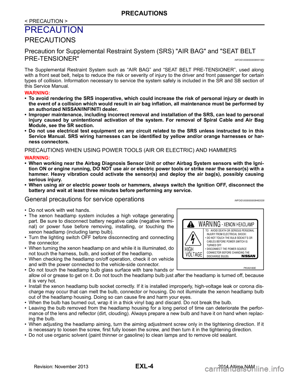
• The xenon headlamp system includes a high voltage generating
part. Be sure to disconnect batte ry negative cable (negative termi-
nal) or power fuse before removing, installing, or touching the
xenon headlamp (including lamp bulb).
• Turn the lighting switch OFF before disconnecting and connecting the connector.
• When turning the xenon headlamp on and while it is illuminated, do
not touch the harness, bulb, and socket of the headlamp.
• When checking the headlamp on/off operation, check it on vehicle and with the power connected to the vehicle-side connector.
• Do not touch the headlamp bulb glass surface with bare hands or allow oil or grease to get on it. Do not touch the headl amp bulb just after the headlamp is turned off, because
it is very hot.
• Install the xenon headlamp bulb socket co rrectly. If it is installed improperly, high-voltage leak or corona dis-
charge may occur that can melt the bulb, connector or housing. Do not illuminate the xenon headlamp bulb
out of the headlamp housing. Doing so can cause fire and harm your eyes.
• When the bulb has burned out, wrap it in a thick vinyl bag and discard. Do not break the bulb.
• Leaving the bulb removed from the headlamp housing for a long period of time can deteriorate the perfor- mance of the lens and reflector (dirt, clouding). Al ways prepare a new bulb and have it on hand when replac-
ing the bulb.
• When adjusting the headlamp aiming, turn the aiming adjus tment screw only in the tightening direction. If it
is necessary to loosen the screw, first fully loosen the screw, and then turn it in the tightening direction.
• Do not use organic solvent (paint thinner or gasoline) to clean lamps and to remove old sealant.
PKIA0183E
Revision: November 20132014 Altima NAMRevision: November 20132014 Altima NAM
Page 2284 of 4801

EXL-18
< SYSTEM DESCRIPTION >
DIAGNOSIS SYSTEM (BCM)
HEADLAMP
HEADLAMP : CONSULT Function (BCM - HEADLAMP)INFOID:0000000009956425
CAUTION:
After disconnecting the CONSULT vehicle interface (VI) from the data link connector, the ignition must
be cycled OFF → ON (for at least 5 seconds) → OFF. If this step is not performed, the BCM may not go
to ”sleep mode”, potentially causing a di scharged battery and a no-start condition.
DATA MONITOR
ACTIVE TEST
RAP system RETAINED PWR ×
Signal buffer system SIGNAL BUFFER ×
TPMS AIR PRESSURE MONITOR ××××
System Sub System
Direct Diagnostic Mode
Ecu Identification
Self Diagnostic Result
Data Monitor
Active Test
Work support
Configuration
CAN Diag Support Mntr
Monitor Item [Unit] Description
PUSH SW [On/Off] Indicates condition of push-button ignition switch.
ENGINE STATE [STOP/STALL/CRANK/RUN] Indicates engine st atus received from ECM on CAN communication line.
VEH SPEED 1 [km/h] Indicates vehicle speed signal received from ABS on CAN communication line.
TURN SIGNAL R [On/Off]
Indicates condition of combination switch.
TURN SIGNAL L [On/Off]
TAIL LAMP SW [On/Off]
HI BEAM SW [On/Off]
HEAD LAMP SW 1 [On/Off]
HEAD LAMP SW 2 [On/Off]
PASSING SW [On/Off]
AUTO LIGHT SW [On/Off]
FR FOG SW [On/Off]
DOOR SW-DR [On/Off] Indicates condition of front door switch LH.
DOOR SW-AS [On/Off] Indicates condition of front door switch RH.
DOOR SW-RR [On/Off] Indicates condition of rear door switch RH.
DOOR SW-RL [On/Off] Indicates condition of rear door switch LH.
DOOR SW-BK [On/Off] Indicates condition of trunk switch.
OPTI SEN (DTCT) [V] Indicates outside brightness voltage signal from optical sensor.
OPTI SEN (FILT) [V] Indicates outside brightness voltage signal from optical sensor filtered by BCM.
Test Item Description
FR FOG LAMP This test is able to check front fog lamp operation [On/Off].
DAYTIME RUNNING LIGHT This test is able to check daytime running la mp operation [On/Off].
ILL DIM SIGNAL This test is able to check head lamp illumination dimming operation [On/Off].
Revision: November 20132014 Altima NAMRevision: November 20132014 Altima NAM
Page 2384 of 4801

EXL-118
< SYMPTOM DIAGNOSIS >
DAYTIME LIGHT SYSTEM INOPERATIVE
DAYTIME LIGHT SYSTEM INOPERATIVE
DescriptionINFOID:0000000009463609
The daytime light system is inoperative even though the combination switch (lighting and turn signal switch)
and parking brake switch are in the normal setting, also whenever engine is operating.
Diagnosis ProcedureINFOID:0000000009463610
1.CHECK DAYTIME LIGHT OPERATION
1. Perform BCM(HEADLAMP) DAYTIME RUNNING LIGHT active test. Refer to BCS-19, "HEADLAMP :
CONSULT Function (BCM - HEADLAMP)".
2. Check that the daytime lights turn on.
Is the inspection results normal?
YES >> Replace BCM. Refer to BCS-80, "Removal and Installation".
NO >> GO TO 2.
2.CHECK DAYTIME LIGHT RELAY FUSE
1. Turn ignition switch OFF.
2. Check that the following fuse is not blown.
Is the fuse blown?
YES >> Replace the blown fuse after repairing the affected circuit.
NO >> GO TO 3.
3.CHECK DAYTIME LIGHT BULBS
Check the daytime light bulbs are not open.
Is the inspection result normal?
YES >> GO TO 4.
NO >> Replace the bulbs.
4.PERFORM DAYTIME LIGH T CIRCUIT INSPECTION
Check the daytime light circuit. Refer to EXL-98, "Diagnosis Procedure"
.
Is the inspection results normal?
YES >> Replace IPDM E/R. Refer to PCS-32, "Removal and Installation".
NO >> Repair or replace the malfunctioning part.
Unit Fuse No. Capacity
Daytime light 43 10 A
Revision: November 20132014 Altima NAMRevision: November 20132014 Altima NAM
Page 2390 of 4801

EXL-124
< PERIODIC MAINTENANCE >
FRONT FOG LAMP
FRONT FOG LAMP
Aiming AdjustmentINFOID:0000000009463618
PREPARATION BEFORE ADJUSTING
The fog lamp is a semi-sealed beam type which uses a replaceable halogen bulb. Before performing aiming
adjustment procedure, check the following:
• Ensure all tires are inflated to correct pressure.
• Place vehicle and screen on level surface.
• Ensure there is no load in vehicle other than the driver (or equivalent weight placed in driver's position).
• Coolant and engine oil filled to correct level, and fuel tank full.
• Remove cargo and/or luggage to maintain an unloaded vehicle condition.
• Confirm spare tire, jack and tools are properly stowed.
• Carefully wipe off any dirt from headlamp lens. CAUTION:
Do not use organic solvent (thinner, gasoline etc.)
• Place a driver or equivalent weight of 68.5 kg (150 lb) on the driver seat.
• By hand, bounce the front and rear of the vehicle to settle the suspension and eliminate any static load.
• Place the front tires in the straight ahead position.
• Aim each headlamp individually and ensure other headlamp beam pattern is blocked from screen.
NOTE:
• For headlamp aiming details, refer to regulations in your area.
• By regulation, no means for horizontal aim adjustment is provided from the factory; only vertical aim is
adjustable.
• Use adjusting screw to perform aiming adjustment.
• Perform headlamp aiming if:
- The vehicle front body has been repaired.
- The front combination lamp has been removed or replaced.
- Any outfitting has been installed.
- The vehicle’s standard load condition has been substantially increased.
Aiming Adjustment Procedure
1. Place the screen. NOTE:
• Stop the vehicle facing the wall.
• Place the board on a plain road vertically.
2. Face the vehicle with the screen. Maintain 7.62 m (25.0 ft) between the front fog lamp center and the
screen.
3. Start the engine. Turn the front fog lamp ON. NOTE:
Shut off the headlamp light with the board to prevent from illuminating the adjustment screen.
CAUTION:
Do not cover the lens surface with a tape etc. The lens is made of resin.
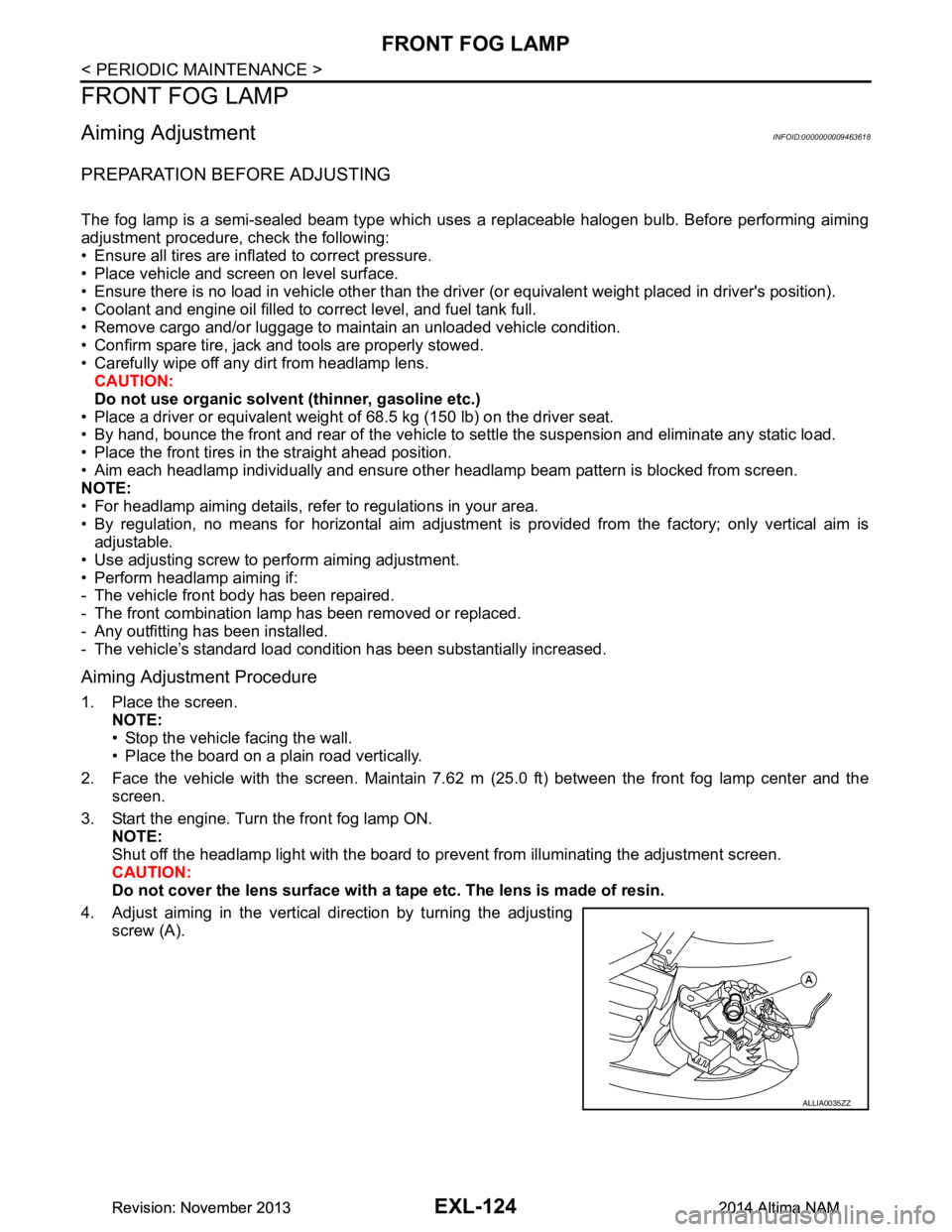
4. Adjust aiming in the vertical direction by turning the adjusting screw (A).
ALLIA0035ZZ
Revision: November 20132014 Altima NAMRevision: November 20132014 Altima NAM
Page 2572 of 4801

GI-44
< BASIC INSPECTION >
SERVICE INFORMATION FOR ELECTRICAL INCIDENT
lowing section illustrates ways to simulate the conditions/environment under which the owner experiences an
electrical incident.
The section is broken into the six following topics:• Vehicle vibration
• Heat sensitive
• Freezing
• Water intrusion
• Electrical load
• Cold or hot start up
Get a thorough description of the incident from the customer . It is important for simulating the conditions of the
problem.
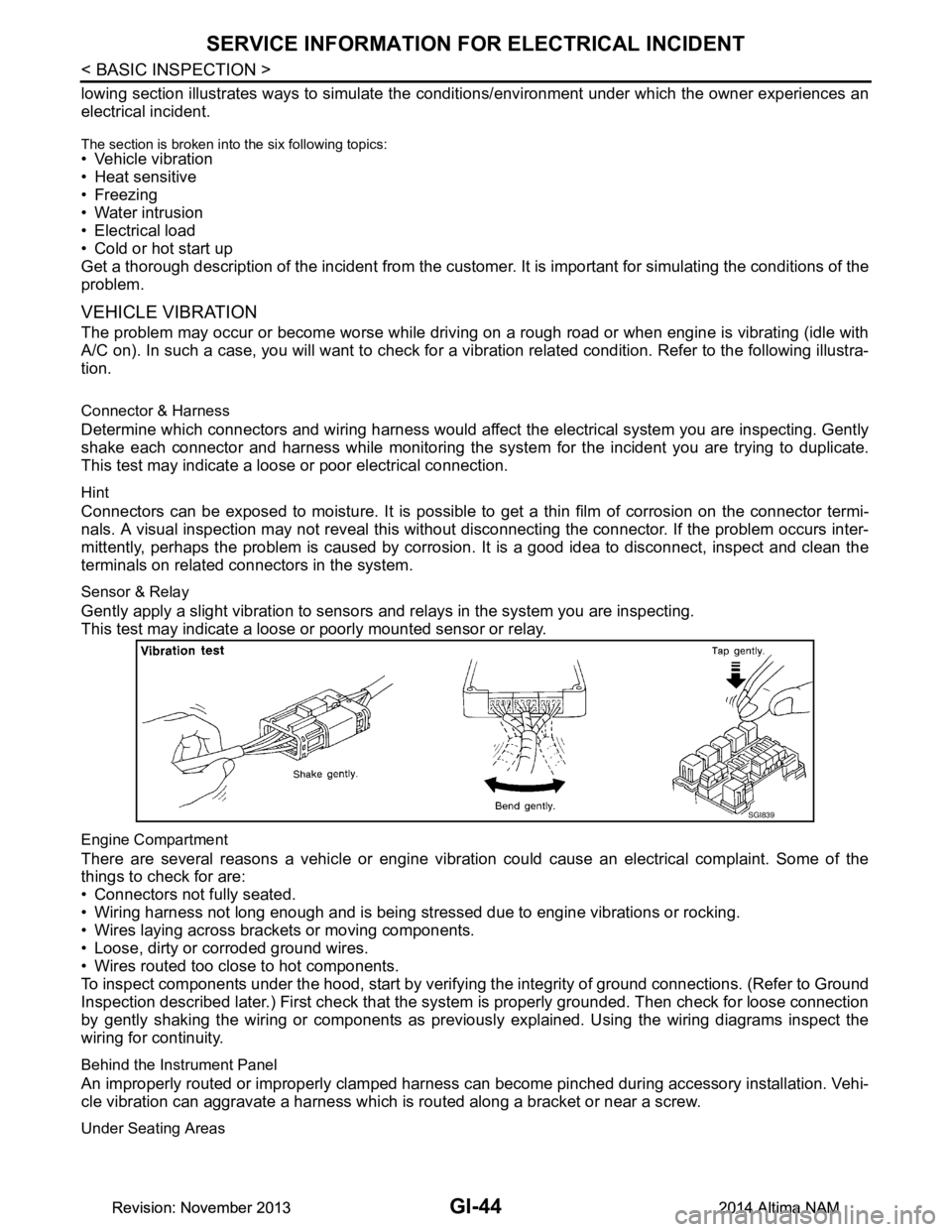
VEHICLE VIBRATION
The problem may occur or become worse while driving on a rough road or when engine is vibrating (idle with
A/C on). In such a case, you will want to check for a vi bration related condition. Refer to the following illustra-
tion.
Connector & Harness
Determine which connectors and wiring harness would affect the electrical system you are inspecting. Gently
shake each connector and harness while monitoring the sy stem for the incident you are trying to duplicate.
This test may indicate a loose or poor electrical connection.
Hint
Connectors can be exposed to moisture. It is possible to get a thin film of corrosion on the connector termi-
nals. A visual inspection may not reveal this without disconnecting the connector. If the problem occurs inter-
mittently, perhaps the problem is caused by corrosion. It is a good idea to disconnect, inspect and clean the
terminals on related connectors in the system.
Sensor & Relay
Gently apply a slight vibration to sensors and relays in the system you are inspecting.
This test may indicate a loose or poorly mounted sensor or relay.
Engine Compartment
There are several reasons a vehicle or engine vibration could cause an electrical complaint. Some of the
things to check for are:
• Connectors not fully seated.
• Wiring harness not long enough and is being stressed due to engine vibrations or rocking.
• Wires laying across brackets or moving components.
• Loose, dirty or corroded ground wires.
• Wires routed too close to hot components.
To inspect components under the hood, start by verifyi ng the integrity of ground connections. (Refer to Ground
Inspection described later.) First check that the system is properly grounded. Then check for loose connection
by gently shaking the wiring or components as previous ly explained. Using the wiring diagrams inspect the
wiring for continuity.
Behind the Instrument Panel
An improperly routed or improperly clamped harness can become pinched during accessory installation. Vehi-
cle vibration can aggravate a harness which is routed along a bracket or near a screw.
Under Seating Areas
SGI839
Revision: November 20132014 Altima NAMRevision: November 20132014 Altima NAM