Page 2866 of 4801
ILLUMINATIONINL-45
< WIRING DIAGRAM >
C
D E
F
G H
I
J
K
M A
B
INL
N
O P
AALIA2332GB
Revision: November 20132014 Altima NAMRevision: November 20132014 Altima NAM
Page 2867 of 4801
INL-46
< WIRING DIAGRAM >
ILLUMINATION
ABLIA5188GB
Revision: November 20132014 Altima NAMRevision: November 20132014 Altima NAM
Page 2871 of 4801

INL-50
< DTC/CIRCUIT DIAGNOSIS >
POWER SUPPLY AND GROUND CIRCUIT
DTC/CIRCUIT DIAGNOSIS
POWER SUPPLY AND GROUND CIRCUIT
BCM
BCM : Diagnosis ProcedureINFOID:0000000009956807
Regarding Wiring Diagram information, refer to BCS-55, "Wiring Diagram".
1. CHECK FUSE AND FUSIBLE LINK
Check that the following fuse and fusible link are not blown.
Is the fuse or fusible link blown?
YES >> Replace the blown fuse or fusible link after repairing the affected circuit.
NO >> GO TO 2
2. CHECK POWER SUPPLY CIRCUIT
1. Disconnect BCM connector M21.
2. Check voltage between BCM connector M21 terminals 131, 139 and ground.
Is the inspection result normal?
YES >> GO TO 3
NO >> Repair or replace harness or connectors.
3. CHECK GROUND CIRCUIT
Check continuity between BCM connector M21 terminals 134, 143 and ground.
Is the inspection result normal?
YES >> Inspection End.
NO >> Repair or replace harness or connectors.
IPDM E/R
IPDM E/R : Diagnosis ProcedureINFOID:0000000009956808
Regarding Wiring Diagram information, refer to PCS-21, "Wiring Diagram".
1. CHECK FUSIBLE LINKS
Terminal No. Signal name Fuse and fusible link No.
139 Fusible link battery power I (40A)
131 BCM battery fuse 1 (10A)
BCM GroundVo l ta g e
(Approx.)
Connector Terminal
M21 131
— Battery voltage
139
BCM Ground Continuity
Connector Terminal
M21 134
—Yes
143
Revision: November 20132014 Altima NAMRevision: November 20132014 Altima NAM
Page 2873 of 4801
INL-52
< DTC/CIRCUIT DIAGNOSIS >
BATTERY SAVER OUTPUT/POWER SUPPLY CIRCUIT
BATTERY SAVER OUTPUT/POWER SUPPLY CIRCUIT
DescriptionINFOID:0000000009463879
Provides the interior room lamp power supply. Also cuts the power supply when the interior room lamp battery
saver is activating.
Component Function CheckINFOID:0000000009463880
1.CHECK BATTERY SAVER OUTPUT /POWER SUPPLY FUNCTION
CONSULT
1. Turn ignition switch ON.
2. Turn each interior room lamp ON.
- Front room/map lamps
- Personal lamps rear
- Front step lamps
- Vanity mirror lamps (if equipped)
- Trunk room lamp
3. Open the driver door to turn ON the front step lamps.
4. Select BATTERY SAVER of BCM (BATTERY SAVER) active test item.
5. While operating the test item, check that each interior room lamp turn ON/OFF.
Is the inspection result normal?
YES >> Interior room lamp power supply circuit is normal.
NO >> Refer to INL-52, "Diagnosis Procedure"
.
Diagnosis ProcedureINFOID:0000000009463881
Regarding Wiring Diagram information, refer to INL-22, "Wiring Diagram".
1.CHECK BATTERY SAVER OUTPUT/POWER SUPPLY OUTPUT
CONSULT
1. Turn ignition switch ON.
2. Select BATTERY SAVER of BCM (BATTERY SAVER) active test item.
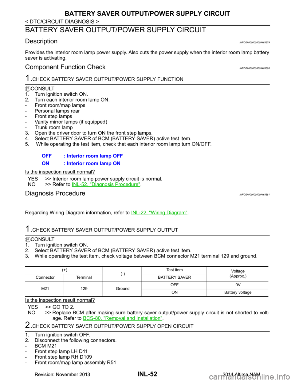
3. While operating the test item, check voltage between BCM connector M21 terminal 129 and ground.
Is the inspection result normal?
YES >> GO TO 2.
NO >> Replace BCM after making sure battery saver out put/power supply circuit is not shorted to volt-
age. Refer to BCS-80, "Removal and Installation"
.
2.CHECK BATTERY SAVER OUTPUT/P OWER SUPPLY OPEN CIRCUIT
1. Turn ignition switch OFF.
2. Disconnect the following connectors.
-BCM M21
- Front step lamp LH D11
- Front step lamp RH D109
- Front room/map lamp assembly R51 OFF : Interior room lamp OFF
ON : Interior room lamp ON
(+) (-)Te s t i t e m
Vo l ta g e
(Approx.)
Connector Terminal BATTERY SAVER
M21 129 Ground OFF 0V
ON Battery voltage
Revision: November 20132014 Altima NAMRevision: November 20132014 Altima NAM
Page 2875 of 4801
INL-54
< DTC/CIRCUIT DIAGNOSIS >
INTERIOR ROOM LAMP CONTROL CIRCUIT
INTERIOR ROOM LAMP CONTROL CIRCUIT
DescriptionINFOID:0000000009463882
Controls the room lamp control circuit (ground side) to turn the room lamps ON and OFF.
Component Function CheckINFOID:0000000009463883
CAUTION:
Before performing the diagnosis, check that the following is normal.
• Battery saver output/power supply
• Front room/map lamp assembly bulbs
• Personal lamp bulbs
1.CHECK INTERIOR ROOM LAMP CONTROL FUNCTION
CONSULT
1. Switch the front room/map lamp assembly switch to DOOR.
2. Turn ignition switch ON.
3. Select INT LAMP of BCM (INT LAMP) active test item.
4. While operating the test item, check that each interior room lamp turn ON/OFF.
Is the inspection result normal?
YES >> Interior room lamp control circuit is normal.
NO >> Refer to INL-54, "Diagnosis Procedure"
.
Diagnosis ProcedureINFOID:0000000009463884
Regarding Wiring Diagram information, refer to INL-22, "Wiring Diagram".
1.CHECK INTERIOR ROOM LAMP CONTROL OUTPUT
CONSULT
1. Turn ignition switch ON.
2. Select INT LAMP of BCM (INT LAMP) active test item.
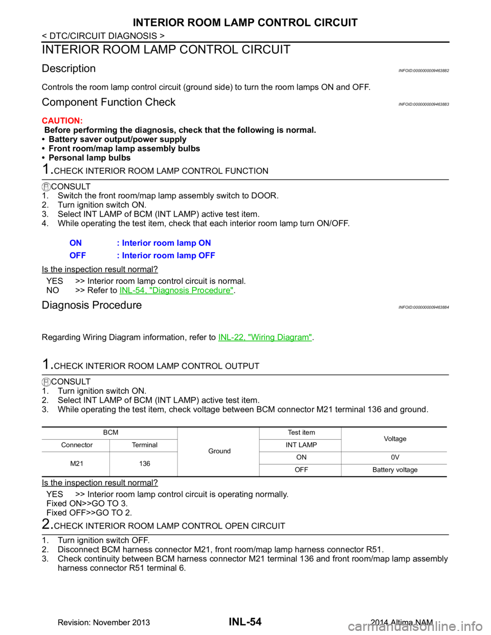
3. While operating the test item, check voltage between BCM connector M21 terminal 136 and ground.
Is the inspection result normal?
YES >> Interior room lamp control circuit is operating normally.
Fixed ON>>GO TO 3.
Fixed OFF>>GO TO 2.
2.CHECK INTERIOR ROOM LA MP CONTROL OPEN CIRCUIT
1. Turn ignition switch OFF.
2. Disconnect BCM harness connector M21, front room/map lamp harness connector R51.
3. Check continuity between BCM harness connector M21 terminal 136 and front room/map lamp assembly
harness connector R51 terminal 6.ON : Interior room lamp ON
OFF : Interior room lamp OFF
BCM
GroundTe s t i t e m
Voltag e
Connector Terminal INT LAMP
M21 136 ON 0V
OFF Battery voltage
Revision: November 20132014 Altima NAMRevision: November 20132014 Altima NAM
Page 2877 of 4801
INL-56
< DTC/CIRCUIT DIAGNOSIS >
STEP LAMP CIRCUIT
STEP LAMP CIRCUIT
DescriptionINFOID:0000000009463885
Controls the step lamp control circuit (ground side) to turn the step lamp ON and OFF.
Component Function CheckINFOID:0000000009463886
CAUTION:
Before performing the diagnosis, check that the following is normal.
• Battery saver output/power supply
• Step lamp bulbs
1.CHECK STEP LAMP OPERATION
CONSULT
1. Turn ignition switch ON.
2. Select STEP LAMP of BCM (I NT LAMP) active test item.
3. While operating the test item, c heck that step lamps turn ON/OFF.
Is the inspection result normal?
YES >> Step lamp circuit is normal.
NO >> Refer to INL-56, "Diagnosis Procedure"
.
Diagnosis ProcedureINFOID:0000000009463887
Regarding Wiring Diagram information, refer to INL-22, "Wiring Diagram".
1.CHECK STEP LAMP OUTPUT
CONSULT
1. Turn ignition switch ON.
2. Select STEP LAMP TEST of BC M (INT LAMP) active test item.
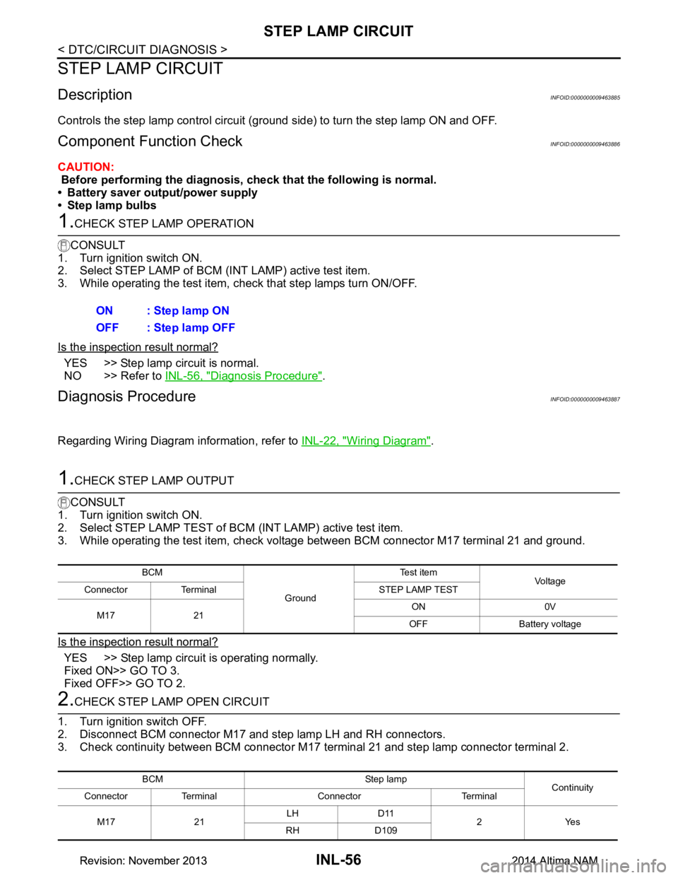
3. While operating the test item, check voltage between BCM connector M17 terminal 21 and ground.
Is the inspection result normal?
YES >> Step lamp circuit is operating normally.
Fixed ON>> GO TO 3.
Fixed OFF>> GO TO 2.
2.CHECK STEP LAMP OPEN CIRCUIT
1. Turn ignition switch OFF.
2. Disconnect BCM connector M17 and step lamp LH and RH connectors.
3. Check continuity between BCM connector M17 terminal 21 and step lamp connector terminal 2.
ON : Step lamp ON
OFF : Step lamp OFF
BCM
GroundTe s t i t e m
Vo l ta g e
Connector Terminal STEP LAMP TEST
M17 21 ON 0V
OFF Battery voltage
BCM Step lamp Continuity
Connector Terminal Connector Terminal
M17 21 LH D11
2Yes
RH D109
Revision: November 20132014 Altima NAMRevision: November 20132014 Altima NAM
Page 2879 of 4801
INL-58
< DTC/CIRCUIT DIAGNOSIS >
TRUNK ROOM LAMP CIRCUIT
TRUNK ROOM LAMP CIRCUIT
DescriptionINFOID:0000000009463888
Controls the trunk room lamp (ground side) to turn the trunk room lamp ON and OFF.
Component Function CheckINFOID:0000000009463889
CAUTION:
Before performing the diagnosis, check that the following is normal.
• Battery saver output/power supply
• Trunk room lamp bulb
1.CHECK TRUNK ROOM LAMP OPERATION
CONSULT
1. Turn ignition switch ON.
2. Select TRUNK/LUGAGE LAMP TEST of BC M (INTELLIGENT KEY) active test item.
3. While operating the test item, check t hat the trunk room lamp turns ON/OFF.
Is the inspection result normal?
YES >> Trunk room lamp circuit is normal.
NO >> Refer to INL-58, "Diagnosis Procedure"
.
Diagnosis ProcedureINFOID:0000000009463890
Regarding Wiring Diagram information, refer to INL-22, "Wiring Diagram".
1.CHECK TRUNK ROOM LAMP OUTPUT
CONSULT
1. Turn ignition switch ON.
2. Select TRUNK/LUGAGE LAMP TEST of BC M (INTELLIGENT KEY) active test item.
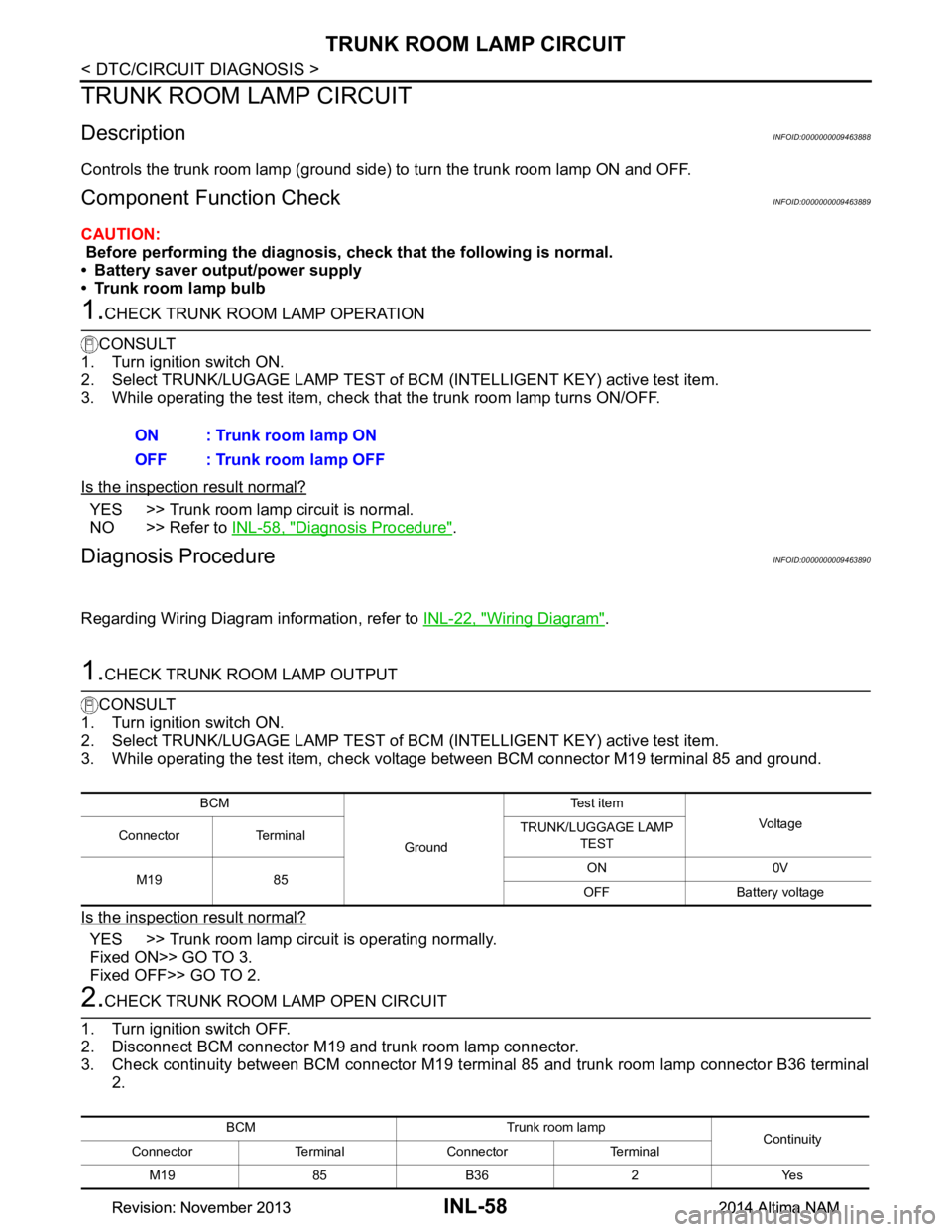
3. While operating the test item, check voltage between BCM connector M19 terminal 85 and ground.
Is the inspection result normal?
YES >> Trunk room lamp circuit is operating normally.
Fixed ON>> GO TO 3.
Fixed OFF>> GO TO 2.
2.CHECK TRUNK ROOM LAMP OPEN CIRCUIT
1. Turn ignition switch OFF.
2. Disconnect BCM connector M19 and trunk room lamp connector.
3. Check continuity between BCM connector M19 terminal 85 and trunk room lamp connector B36 terminal 2.ON : Trunk room lamp ON
OFF : Trunk room lamp OFF
BCM
GroundTe s t i t e m
Vol tag e
Connector Terminal TRUNK/LUGGAGE LAMP
TEST
M19 85 ON 0V
OFF Battery voltage
BCM Trunk room lamp Continuity
Connector Terminal Connector Terminal
M19 85 B36 2 Yes
Revision: November 20132014 Altima NAMRevision: November 20132014 Altima NAM
Page 2881 of 4801
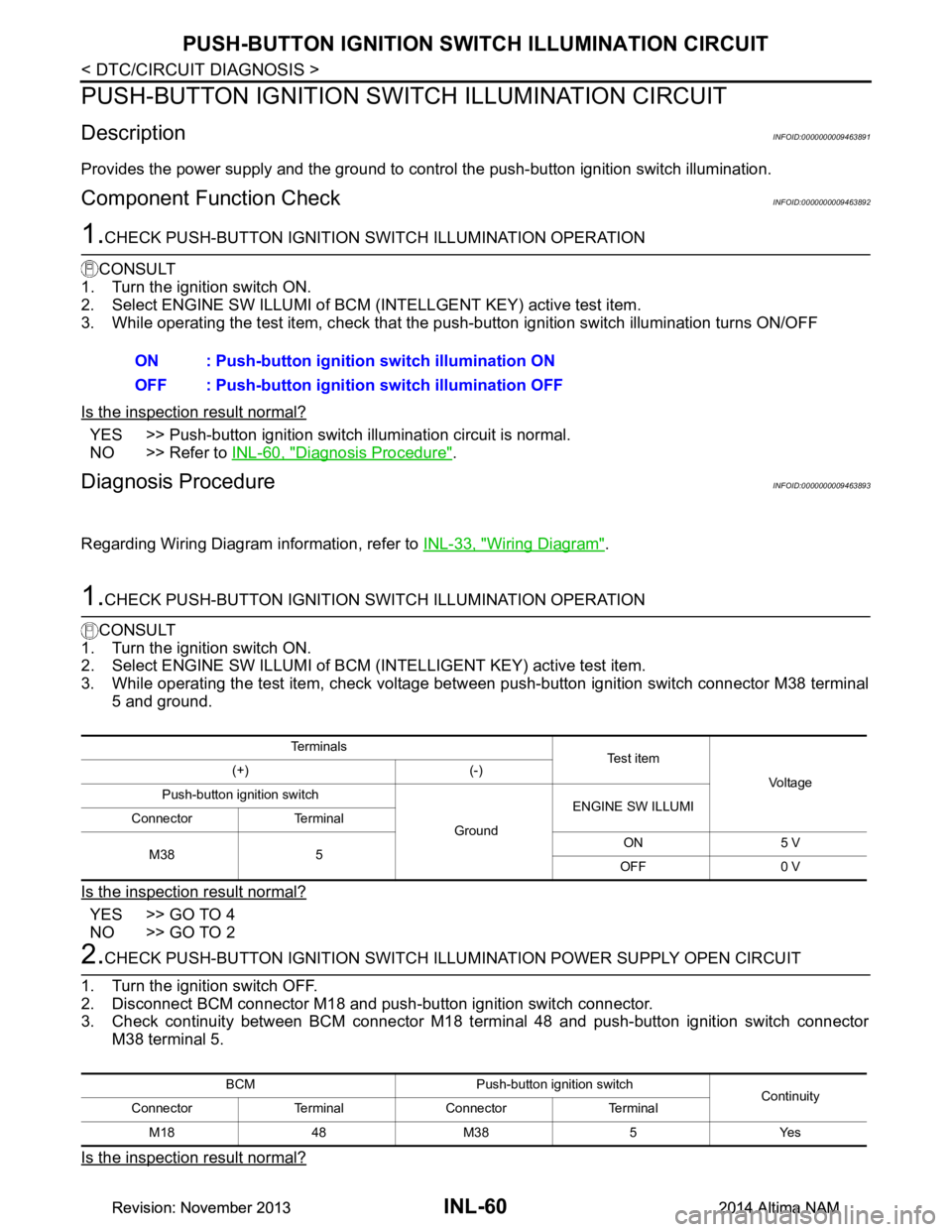
INL-60
< DTC/CIRCUIT DIAGNOSIS >
PUSH-BUTTON IGNITION SWITCH ILLUMINATION CIRCUIT
PUSH-BUTTON IGNITION SWITCH ILLUMINATION CIRCUIT
DescriptionINFOID:0000000009463891
Provides the power supply and the ground to contro l the push-button ignition switch illumination.
Component Function CheckINFOID:0000000009463892
1.CHECK PUSH-BUTTON IGNITION SWITCH ILLUMINATION OPERATION
CONSULT
1. Turn the ignition switch ON.
2. Select ENGINE SW ILLUMI of BCM (I NTELLGENT KEY) active test item.
3. While operating the test item, c heck that the push-button ignition switch illumination turns ON/OFF
Is the inspection result normal?
YES >> Push-button ignition switch illumination circuit is normal.
NO >> Refer to INL-60, "Diagnosis Procedure"
.
Diagnosis ProcedureINFOID:0000000009463893
Regarding Wiring Diagram information, refer to INL-33, "Wiring Diagram".
1.CHECK PUSH-BUTTON IGNITION SWITCH ILLUMINATION OPERATION
CONSULT
1. Turn the ignition switch ON.
2. Select ENGINE SW ILLUMI of BCM (INTELLIGENT KEY) active test item.
3. While operating the test item, check voltage betw een push-button ignition switch connector M38 terminal
5 and ground.
Is the inspection result normal?
YES >> GO TO 4
NO >> GO TO 2
2.CHECK PUSH-BUTTON IGNITION SWITCH ILLU MINATION POWER SUPPLY OPEN CIRCUIT
1. Turn the ignition switch OFF.
2. Disconnect BCM connector M18 and push-button ignition switch connector.
3. Check continuity between BCM connector M18 terminal 48 and push-button ignition switch connector
M38 terminal 5.
Is the inspection result normal?
ON : Push-button ignition switch illumination ON
OFF : Push-button ignition switch illumination OFF
Te r m i n a l s
Te s t i t e m
Vo l ta g e
(+) (-)
Push-button ignition switch
GroundENGINE SW ILLUMI
Connector Terminal
M38 5 ON 5 V
OFF 0 V
BCM Push-button ignition switch Continuity
Connector Terminal Connector Terminal
M1848M38 5 Yes
Revision: November 20132014 Altima NAMRevision: November 20132014 Altima NAM