2014 NISSAN TEANA width
[x] Cancel search: widthPage 2544 of 4801

GI-16
< HOW TO USE THIS MANUAL >
ABBREVIATIONS
P
R
S
T
U
V
OL Open loop
OSS Output shaft speed
ABBREVIATION DESCRIPTION P/S Power steering
PBR Potentio balance resistor
PCV Positive crankcase ventilation
PNP Park/Neutral position PSP Power steering pressurePTC Positive temperature coefficient
PTO Power takeoff
PWM Pulse width modulation
ABBREVIATION DESCRIPTION RAM Random access memoryRAS Rear active steer RH Right-hand
ROM Read only memory RPM Engine speed RR Rear
ABBREVIATION DESCRIPTION SAE Society of Automotive Engineers, Inc.
SCK Serial clock
SDS Service Data and Specifications SRT System readiness testSST Special Service Tools
ABBREVIATION DESCRIPTION TC Turbocharger
TCM Transmission control module TCS Traction control system
TCU Telematics communication unit TP Throttle position
TPMS Tire pressure monitoring system TSS Turbine shaft speed
TWC Three way catalytic converter
ABBREVIATION DESCRIPTION USS Uphill start support
ABBREVIATION DESCRIPTION VCM Vehicle control moduleVDC Vehicle dynamics control system
ABBREVIATION DESCRIPTION
Revision: November 20132014 Altima NAMRevision: November 20132014 Altima NAM
Page 2546 of 4801

GI-18
< HOW TO USE THIS MANUAL >
TIGHTENING TORQUE OF STANDARD BOLTS
TIGHTENING TORQUE OF STANDARD BOLTS
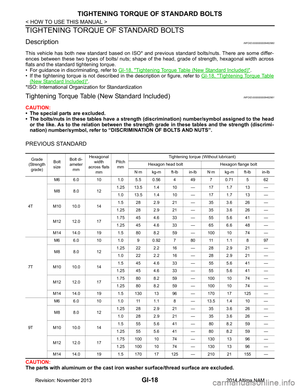
DescriptionINFOID:0000000009462980
This vehicle has both new standard based on ISO* and previous standard bolts/nuts. There are some differ-
ences between these two types of bolts/ nuts; shape of the head, grade of strength, hexagonal width across
flats and the standard tightening torque.
• For guidance in discriminating, refer to GI-18, "Tightening Torque Table (New Standard Included)"
.
• If the tightening torque is not described in the description or figure, refer to GI-18, "Tightening Torque Table
(New Standard Included)".
*ISO: International Organization for Standardization
Tightening Torque Tabl e (New Standard Included)INFOID:0000000009462981
CAUTION:
• The special parts are excluded.
• The bolts/nuts in these tables have a strength (d iscrimination) number/symbol assigned to the head
or the like. As to the relation between the stre ngth grade in these tables and the strength (discrimi-
nation) number/symbol, refer to “DISCRIMINATION OF BOLTS AND NUTS”.
PREVIOUS STANDARD
CAUTION:
The parts with aluminum or the cast iron washer surface/thread surface are excluded.
Grade
(Strength
grade) Bolt
size Bolt di-
ameter
mm Hexagonal
width
across flats mm Pitch
mm Tightening torque (Without lubricant)
Hexagon head bolt Hexagon flange bolt
N·m kg-m ft-lb in-lb N·m kg-m ft-lb in-lb
4T M6 6.0 10 1.0 5.5 0.56 4 49 7 0.71 5 62
M8 8.0 12 1.25 13.5 1.4 10 — 17 1.7 13 —
1.0 13.5 1.4 10 — 17 1.7 13 —
M10 10.0 14 1.5 28 2.9 21 — 35 3.6 26 —
1.25 28 2.9 21 — 35 3.6 26 —
M12 12.0 17 1.75 45 4.6 33 — 55 5.6 41 —
1.25 45 4.6 33 — 65 6.6 48 —
M14 14.0 19 1.5 80 8.2 59 — 100 10 74 —
7T M6 6.0 10 1.0 9 0.92 7 80 11 1.1 8 97
M8 8.0 12 1.25 22 2.2 16 — 28 2.9 21 —
1.0 22 2.2 16 — 28 2.9 21 —
M10 10.0 14 1.5 45 4.6 33 — 55 5.6 41 —
1.25 45 4.6 33 — 55 5.6 41 —
M12 12.0 17 1.75 80 8.2 59 — 100 10 74 —
1.25 80 8.2 59 — 100 10 74 —
M14 14.0 19 1.5 130 13 96 — 170 17 125 —
9T M6 6.0 10 1.0 11 1.1 8 — 13.5 1.4 10 —
M8 8.0 12 1.25 28 2.9 21 — 35 3.6 26 —
1.0 28 2.9 21 — 35 3.6 26 —
M10 10.0 14 1.5 55 5.6 41 — 80 8.2 59 —
1.25 55 5.6 41 — 80 8.2 59 —
M12 12.0 17 1.75 100 10 74 — 130 13 96 —
1.25 100 10 74 — 130 13 96 —
M14 14.0 19 1.5 170 17 125 — 210 21 155 —
Revision: November 20132014 Altima NAMRevision: November 20132014 Altima NAM
Page 2547 of 4801

TIGHTENING TORQUE OF STANDARD BOLTSGI-19
< HOW TO USE THIS MANUAL >
C
D E
F
G H
I
J
K L
M B
GI
N
O P
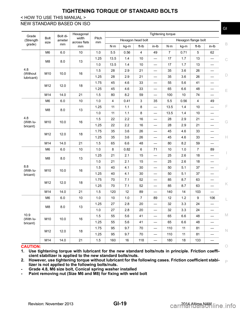
NEW STANDARD BASED ON ISO
CAUTION:
1. Use tightening torque with lubricant for the new standard bolts/nuts in principle. Friction coeffi- cient stabilizer is applied to the new standard bolts/nuts.
2. However, use tightening torque wi thout lubricant for the following cases. Friction coefficient stabi-
lizer is not applied to the following bolts/nuts.
- Grade 4.8, M6 size bolt, Co nical spring washer installed
- Paint removing nut (Size M6 and M8) for fixing with weld bolt
Grade
(Strength grade) Bolt
size Bolt di-
ameter mm Hexagonal
width
across flats
mm Pitch
mm Tightening torque
Hexagon head bolt Hexagon flange bolt
N·m kg-m ft-lb in-lb N·m kg-m ft-lb in-lb
4.8
(Without
lubricant) M6 6.0 10 1.0 5.5 0.56 4 49 7 0.71 5 62
M8 8.0 13 1.25 13.5 1.4 10 — 17 1.7 13 —
1.0 13.5 1.4 10 — 17 1.7 13 —
M10 10.0 16 1.5 282.921 — 353.626 —
1.25 28 2.9 21 — 35 3.6 26 —
M12 12.0 18 1.75 45 4.6 33 — 55 5.6 41 —
1.25 45 4.6 33 — 65 6.6 48 —
M14 14.0 21 1.5 80 8.2 59 — 100 10 74 —
4.8
(With lu-
bricant) M6 6.0 10 1.0 40.413 355.50.564 49
M8 8.0 13 1.25 11 1.1 8 — 13.5 1.4 10 —
1.0 11 1.1 8 — 13.5 1.4 10 —
M10 10.0 16 1.5 222.216 — 282.921 —
1.25 22 2.2 16 — 28 2.9 21 —
M12 12.0 18 1.75 35 3.6 26 — 45 4.6 33 —
1.25 35 3.6 26 — 45 4.6 33 —
M14 14.0 21 1.5 65 6.6 48 — 80 8.2 59 —
8.8
(With lu-
bricant) M6 6.0 10 1.0 8 0.82 6 71 10 1.0 7 89
M8 8.0 13 1.25 21 2.1 15 — 25 2.6 18 —
1.0 212.115 — 252.618 —
M10 10.0 16 1.5 404.130 — 505.137 —
1.25 40 4.1 30 — 50 5.1 37 —
M12 12.0 18 1.75 70 7.1 52 — 85 8.7 63 —
1.25 70 7.1 52 — 85 8.7 63 —
M14 14.0 21 1.5 120 12 89 — 140 14 103 —
10.9
(With lu-
bricant) M6 6.0 10 1.0 10 1.0 7 89 12 1.2 9 106
M8 8.0 13 1.25 27 2.8 20 — 32 3.3 24 —
1.0 272.820 — 323.324 —
M10 10.0 16 1.5 555.641 — 656.648 —
1.25 55 5.6 41 — 65 6.6 48 —
M12 12.0 18 1.75 95 9.7 70 — 110 11 81 —
1.25 95 9.7 70 — 110 11 81 —
M14 14.0 21 1.5 160 16 118 — 180 18 133 —
Revision: November 20132014 Altima NAMRevision: November 20132014 Altima NAM
Page 2553 of 4801

IDENTIFICATION INFORMATIONGI-25
< VEHICLE INFORMATION >
C
D E
F
G H
I
J
K L
M B
GI
N
O P
VQ35DE
CVT NumberINFOID:0000000009462988
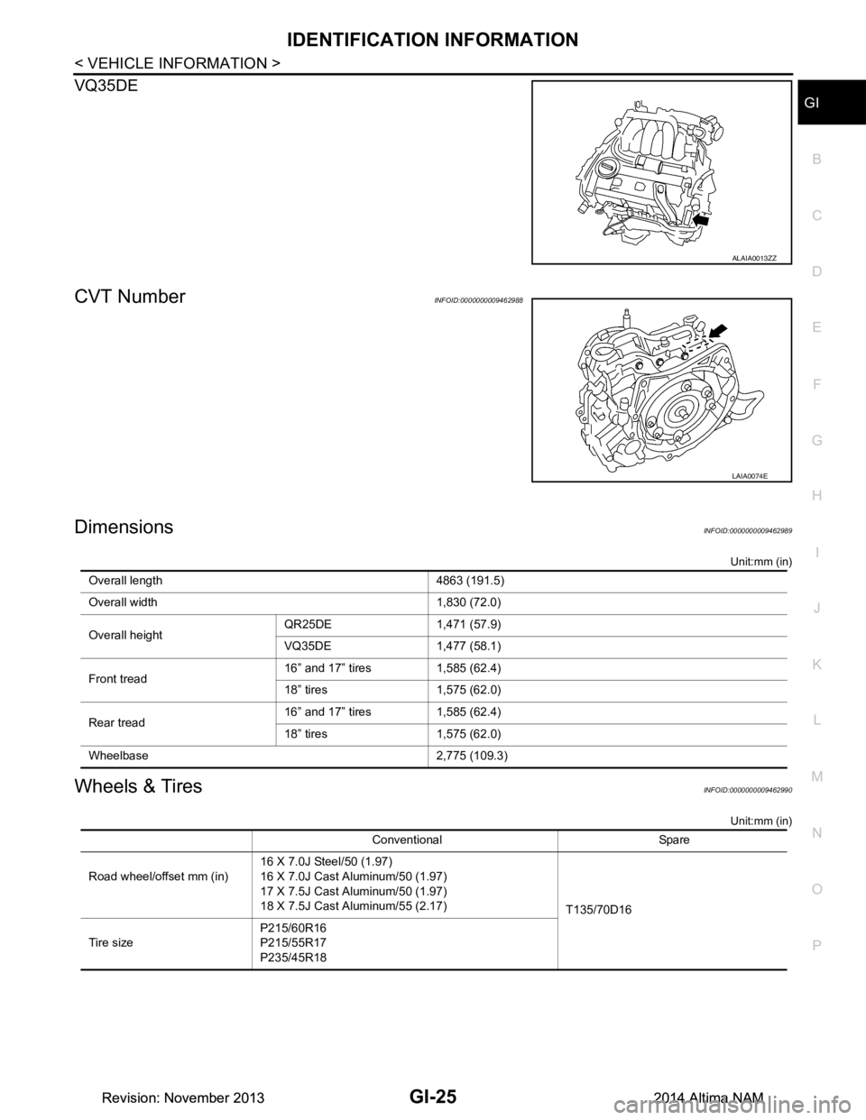
DimensionsINFOID:0000000009462989
Unit:mm (in)
Wheels & TiresINFOID:0000000009462990
Unit:mm (in)
ALAIA0013ZZ
LAIA0074E
Overall length 4863 (191.5)
Overall width 1,830 (72.0)
Overall height QR25DE 1,471 (57.9)
VQ35DE 1,477 (58.1)
Front tread 16” and 17” tires 1,585 (62.4)
18” tires 1,575 (62.0)
Rear tread 16” and 17” tires 1,585 (62.4)
18” tires 1,575 (62.0)
Wheelbase 2,775 (109.3)
Conventional Spare
Road wheel/offset mm (in) 16 X 7.0J Steel/50 (1.97)
16 X 7.0J Cast Aluminum/50 (1.97)
17 X 7.5J Cast Aluminum/50 (1.97)
18 X 7.5J Cast Aluminum/55 (2.17) T135/70D16
Tire size P215/60R16
P215/55R17
P235/45R18
Revision: November 20132014 Altima NAMRevision: November 20132014 Altima NAM
Page 4238 of 4801
![NISSAN TEANA 2014 Service Manual
STRUCTURE AND OPERATIONTM-23
< SYSTEM DESCRIPTION > [CVT: RE0F10D]
C
EF
G H
I
J
K L
M A
B
TM
N
O P
TRANSAXLE : Operation StatusINFOID:0000000009463981
× : Engaged or applied.
TRANSAXLE : Transaxle NISSAN TEANA 2014 Service Manual
STRUCTURE AND OPERATIONTM-23
< SYSTEM DESCRIPTION > [CVT: RE0F10D]
C
EF
G H
I
J
K L
M A
B
TM
N
O P
TRANSAXLE : Operation StatusINFOID:0000000009463981
× : Engaged or applied.
TRANSAXLE : Transaxle](/manual-img/5/57390/w960_57390-4237.png)
STRUCTURE AND OPERATIONTM-23
< SYSTEM DESCRIPTION > [CVT: RE0F10D]
C
EF
G H
I
J
K L
M A
B
TM
N
O P
TRANSAXLE : Operation StatusINFOID:0000000009463981
× : Engaged or applied.
TRANSAXLE : Transaxle MechanismINFOID:0000000009463982
TORQUE CONVERTER (WITH LOCK-UP FUNCTION)
In the same way as a conventional A/T, the torque c onverter is a system that increases the engine torque and
transmits the torque to the transaxle. A symmetr ical 3-element, 1-stage, 2-phase type is used here.
OIL PUMP
Utilizes a vane-type oil pump that is driven by the engi ne through the oil pump drive chain in order to increase
efficiency of pump discharge volume in low-speed zone and optimize pump discharge volume in high-speed
zone. Discharged oil from oil pump is transmitted to contro l valve. It is used as the oil of primary and second-
ary pulley operation, the oil of clutch operation, and the lubricant for each part.
PLANETARY GEAR
• A planetary gear type of forward/reverse selector me chanism is installed between the torque converter and
primary pulley.
• The power from the torque converter is input via the i nput shaft, operating a wet multi-plate clutch by means
of hydraulic pressure to switch between forward and reverse driving.
Operation of Planetary gear
BELT & PULLEY
It is composed of a pair of pulleys (the groove width is changed freely in the axial direction) and the steel belt
(the steel plates are placed conti nuously and the belt is guided with the multilayer steel rings on both sides).
Selector lever
position Parking mech-
anism Forward
clutch Reverse brake Primary pulley Secondary
pulley Steel belt Final drive
P ×
R ×××××
N
D × ××××
DS × ××××
JSDIA2426GB
Revision: November 20132014 Altima NAMRevision: November 20132014 Altima NAM
Page 4239 of 4801
![NISSAN TEANA 2014 Service Manual
TM-24
< SYSTEM DESCRIPTION >[CVT: RE0F10D]
STRUCTURE AND OPERATION
The groove width changes according to wrapping radius of
steel belt and pulley from low status to overdrive
status continuously wit NISSAN TEANA 2014 Service Manual
TM-24
< SYSTEM DESCRIPTION >[CVT: RE0F10D]
STRUCTURE AND OPERATION
The groove width changes according to wrapping radius of
steel belt and pulley from low status to overdrive
status continuously wit](/manual-img/5/57390/w960_57390-4238.png)
TM-24
< SYSTEM DESCRIPTION >[CVT: RE0F10D]
STRUCTURE AND OPERATION
The groove width changes according to wrapping radius of
steel belt and pulley from low status to overdrive
status continuously with non-step. It is controlled wit h the oil pressures of primary pulley and secondary pulley.
Steel Belt
It is composed of multiple steel plates (A) and two steel rings (B)
stacked to a several number. The feature of this steel belt transmits
power with compression of the steel plate in contrast with transmis-
sion of power in pulling with a rubber belt. Friction force is required
with the pulley slope to transmit power from the steel plate. The force
is generated with the following mechanism:
Oil pressure applies to the secondary pulley to nip the plate. ⇒The
plate is pushed and extended outward. ⇒The steel ring shows with-
stands. ⇒Pulling force is generated on the steel ring. ⇒The plate of
the primary pulley is nipped between the pulley. ⇒Friction force is
generated between the steel belt and the pulley.
Therefore, responsibilities are divi ded by the steel plate that trans-
mits the power with compression and the steel ring that main tains necessary friction force. In this way, the
tension of the steel ring is distributed on the entire su rface and stress variation is limited, resulting in good
durability.
Pulley
The primary pulley (input shaft side) and the secondary pulley (output shaft side) have the shaft with slope
(fixed cone surface), movable sheave (movable cone surface that can move in the axial direction) and oil pres-
sure chamber at the back of the movable sheave.
JSDIA2428GB
JSDIA2431ZZ
Revision: November 20132014 Altima NAMRevision: November 20132014 Altima NAM
Page 4240 of 4801
![NISSAN TEANA 2014 Service Manual
STRUCTURE AND OPERATIONTM-25
< SYSTEM DESCRIPTION > [CVT: RE0F10D]
C
EF
G H
I
J
K L
M A
B
TM
N
O P
The movable sheave slides on the shaft to change the gr oove width of the pulley. Input signals of NISSAN TEANA 2014 Service Manual
STRUCTURE AND OPERATIONTM-25
< SYSTEM DESCRIPTION > [CVT: RE0F10D]
C
EF
G H
I
J
K L
M A
B
TM
N
O P
The movable sheave slides on the shaft to change the gr oove width of the pulley. Input signals of](/manual-img/5/57390/w960_57390-4239.png)
STRUCTURE AND OPERATIONTM-25
< SYSTEM DESCRIPTION > [CVT: RE0F10D]
C
EF
G H
I
J
K L
M A
B
TM
N
O P
The movable sheave slides on the shaft to change the gr oove width of the pulley. Input signals of engine load
(accelerator pedal opening), primary pulley speed and secondary pulley speed change the operation pres-
sures of the primary pulley and the secondary pulley, and controls the pulley groove width.
FINAL DRIVE AND DIFFERENTIAL
The deceleration gears are composed of 2 stages: primar y deceleration (output gear, idler gear pair) and sec-
ondary deceleration (reduction gear, final gear pa ir). All of these gears are helical gears.
JSDIA2429GB
Revision: November 20132014 Altima NAMRevision: November 20132014 Altima NAM
Page 4242 of 4801
![NISSAN TEANA 2014 Service Manual
STRUCTURE AND OPERATIONTM-27
< SYSTEM DESCRIPTION > [CVT: RE0F10D]
C
EF
G H
I
J
K L
M A
B
TM
N
O P
TRANSAXLE : Component DescriptionINFOID:0000000009463984
FLUID COOLER & FLUID WARMER SYSTEM
Part na NISSAN TEANA 2014 Service Manual
STRUCTURE AND OPERATIONTM-27
< SYSTEM DESCRIPTION > [CVT: RE0F10D]
C
EF
G H
I
J
K L
M A
B
TM
N
O P
TRANSAXLE : Component DescriptionINFOID:0000000009463984
FLUID COOLER & FLUID WARMER SYSTEM
Part na](/manual-img/5/57390/w960_57390-4241.png)
STRUCTURE AND OPERATIONTM-27
< SYSTEM DESCRIPTION > [CVT: RE0F10D]
C
EF
G H
I
J
K L
M A
B
TM
N
O P
TRANSAXLE : Component DescriptionINFOID:0000000009463984
FLUID COOLER & FLUID WARMER SYSTEM
Part name Function
Torque converter Increases engine torque and transmits it to the transaxle.
Oil pump Utilizes a vane-type oil pump that is driven by the engine through the oil pump drive chain in order to
increase efficiency of pump discharge volume in low-speed zone and optimize pump discharge volume
in high-speed zone. Discharged oil from oil pump is tr ansmitted to control valve. It is used as the oil of
primary and secondary pulley operation, the oil of clutch operation, and the lubricant for each part.
Forward clutch The forward clutch is wet and multiple plate type clutch that consists of clutch drum, piston, drive plate,
and driven plate. It is a clutch to move the vehicle forward by activating piston hydraulically, engaging
plates, and directly connecting sun gear and input shaft.
Reverse brake The reverse brake is a wet multiple-plate type brake that consists of transaxle case, piston, drive plate,
and driven plate. It is a brake to move the vehicle in reverse by activating piston hydraulically, engaging
plates, and fixing planetary gear.
Internal gear The internal gear is directly connected to forward clutch drum. It is a gear that moves the outer edge of
pinion planet of planet carrier. It transmits power to move the vehicle in reverse when the planet carrier
is fixed.
Planet carrier Composed of a carrier, pinion planet, and pinion shaft. This gear fixes and releases the planet carrier in
order to switch between forward and reverse driving.
Sun gear Sun gear is a set part with planet carrier and internal gear. It transmits transmitted force to primary fixed
sheave. It rotates in forward or reverse direction according to activation of either forward clutch or re-
verse brake.
Input shaft The input shaft is directly connected to forward clutch drum and transmits traction force from torque con-
verter. In shaft center, there are holes for hydraulic distribution to primary pulley and hydraulic distribution
for lockup ON/OFF.
Primary pulley It is composed of a pair of pulleys (the groove width is changed freely in the axial direction) and the steel belt. The groove width changes according to wrapping radius of steel belt and pulley from low status to
overdrive status continuously with non-step. It is controlled with the oil pressures of primary pulley and
secondary pulley.
Secondary pulley
Steel belt
Manual shaft When the manual shaft is in the P position, the parking rod that is linked to the manual shaft rotates the
parking pole. When the parking pole rotates, it engages with the parking gear, fixing the parking gear. As
a result, the secondary pulley that is integrated with the parking gear is fixed.
Parking rod
Parking pawl
Parking gear
Output gear
The deceleration gears are composed of 2 stages: primary deceleration (output gear, idler gear pair) and
secondary deceleration (reduction gear, final gear pair). All of these gears are helical gears.
Idler gear
Reduction gear
Differential
Torque converter regulator
valve Adjusts the feed pressure to the torque converter to the optimum pressure corresponding to the driving
condition.
Pressure regulator valve Adjusts the discharge pressure from the oil pump to the optimum pressure (line pressure) corresponding
to the driving condition.
Torque converter clutch
control valve Adjusts the torque converter engage and disengage pressures.
Manual valve Distributes the clutch operation pressure to each circuit according to the selector lever position.
Secondary reducing valve Reduces line pressure and adjusts secondary pressure.
Primary reducing valve Reduces line pressure and adjusts primary pressure.
Pilot valve A Reduces line pressure and adjusts pilot pressure to the solenoid valves listed below.
• Primary pressure solenoid valve
• Secondary pressure solenoid valve
• Select solenoid valve
• Line pressure solenoid valve
Pilot valve B Reduces pilot pressure and adjusts pilot pressure to the torque converter clutch solenoid valve.
Revision: November 20132014 Altima NAMRevision: November 20132014 Altima NAM