2014 NISSAN TEANA boot
[x] Cancel search: bootPage 3229 of 4801
CHASSIS AND BODY MAINTENANCEMA-45
< PERIODIC MAINTENANCE >
C
D E
F
G H
I
J
K L
M B
MA
N
O A
DRIVE SHAFT
DRIVE SHAFT : InspectionINFOID:0000000009464590
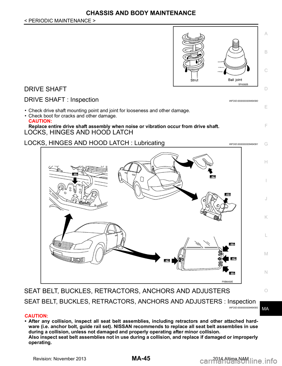
• Check drive shaft mounting point and joint for looseness and other damage.
• Check boot for cracks and other damage.
CAUTION:
Replace entire drive shaft assembly when noi se or vibration occur from drive shaft.
LOCKS, HINGES AND HOOD LATCH
LOCKS, HINGES AND HOOD LATCH : LubricatingINFOID:0000000009464591
SEAT BELT, BUCKLES, RETRAC TORS, ANCHORS AND ADJUSTERS
SEAT BELT, BUCKLES, RETRACTORS, ANCHORS AND ADJUSTERS : Inspection
INFOID:0000000009464592
CAUTION:
• After any collision, inspect all seat belt assembli es, including retractors and other attached hard-
ware (i.e. anchor bolt, guide ra il set). NISSAN recommends to repl ace all seat belt assemblies in use
during a collision, unless not damaged an d properly operating after minor collision.
Also inspect seat belt assemblies no t in use during a collision, and replace if damaged or improperly
operating.
SFA392B
PIIB6450E
Revision: November 20132014 Altima NAM
Page 4118 of 4801
POWER STEERING FLUIDST-15
< BASIC INSPECTION >
C
D E
F
H I
J
K L
M A
B
ST
N
O P
POWER STEERING FLUID
InspectionINFOID:0000000009461251
FLUID LEVEL
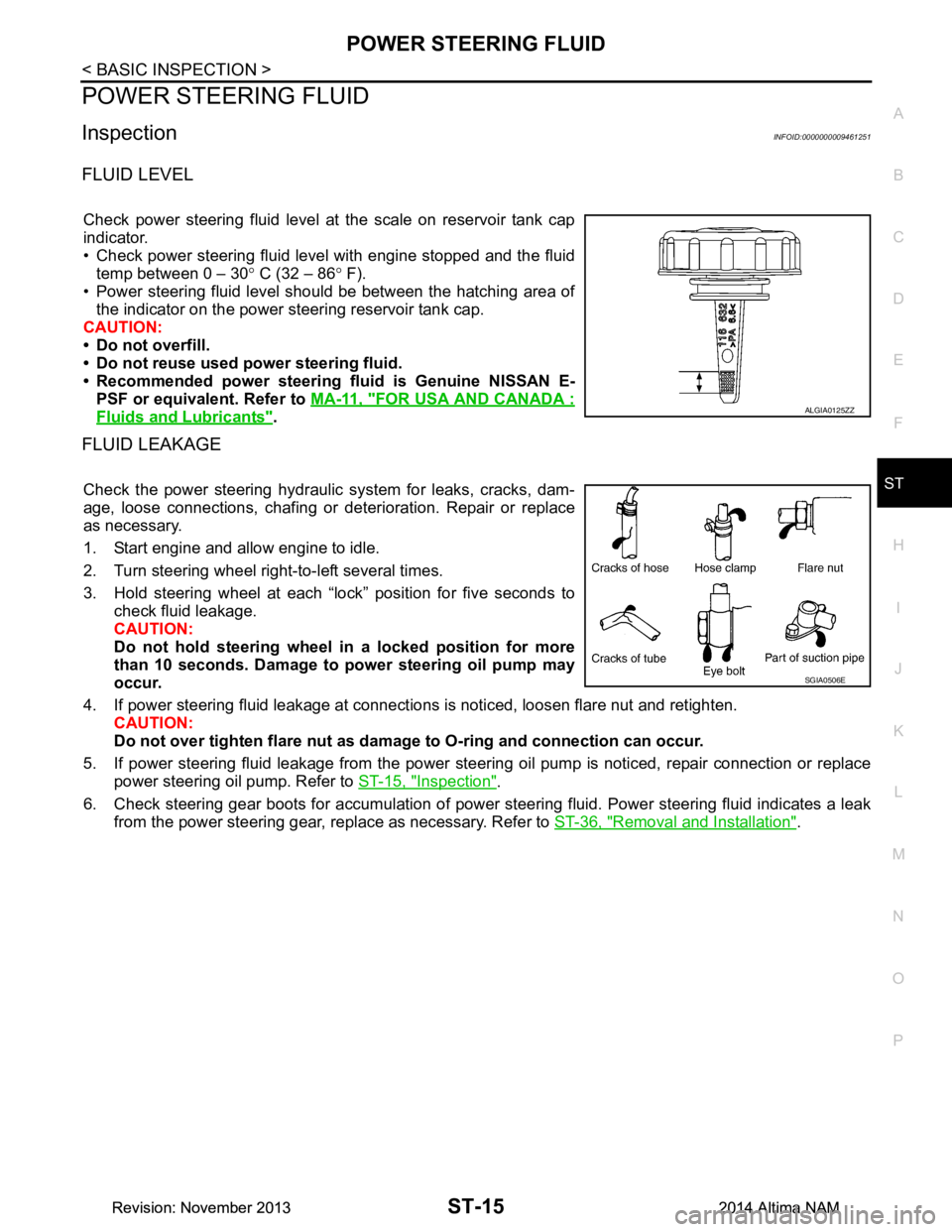
Check power steering fluid level at the scale on reservoir tank cap
indicator.
• Check power steering fluid level with engine stopped and the fluid temp between 0 – 30 ° C (32 – 86 ° F).
• Power steering fluid level should be between the hatching area of the indicator on the power steering reservoir tank cap.
CAUTION:
• Do not overfill.
• Do not reuse used power steering fluid.
• Recommended power steering fluid is Genuine NISSAN E-
PSF or equivalent. Refer to MA-11, "FOR USA AND CANADA :
Fluids and Lubricants".
FLUID LEAKAGE
Check the power steering hydraulic system for leaks, cracks, dam-
age, loose connections, chafing or det erioration. Repair or replace
as necessary.
1. Start engine and allow engine to idle.
2. Turn steering wheel right-to-left several times.
3. Hold steering wheel at each “lock” position for five seconds to check fluid leakage.
CAUTION:
Do not hold steering wheel in a locked position for more
than 10 seconds. Damage to power steering oil pump may
occur.
4. If power steering fluid leakage at connections is noticed, loosen flare nut and retighten.
CAUTION:
Do not over tighten flare nut as damage to O-ring and connection can occur.
5. If power steering fluid leakage from the power steer ing oil pump is noticed, repair connection or replace
power steering oil pump. Refer to ST-15, "Inspection"
.
6. Check steering gear boots for accumulation of power st eering fluid. Power steering fluid indicates a leak
from the power steering gear, replace as necessary. Refer to ST-36, "Removal and Installation"
.
ALGIA0125ZZ
SGIA0506E
Revision: November 20132014 Altima NAMRevision: November 20132014 Altima NAM
Page 4123 of 4801
ST-20
< BASIC INSPECTION >
STEERING GEAR AND LINKAGE
STEERING GEAR AND LINKAGE
InspectionINFOID:0000000009461255
BOOT
Check boot for cracks. Replace if any damage is found.
OUTER SOCKET AND INNER SOCKET
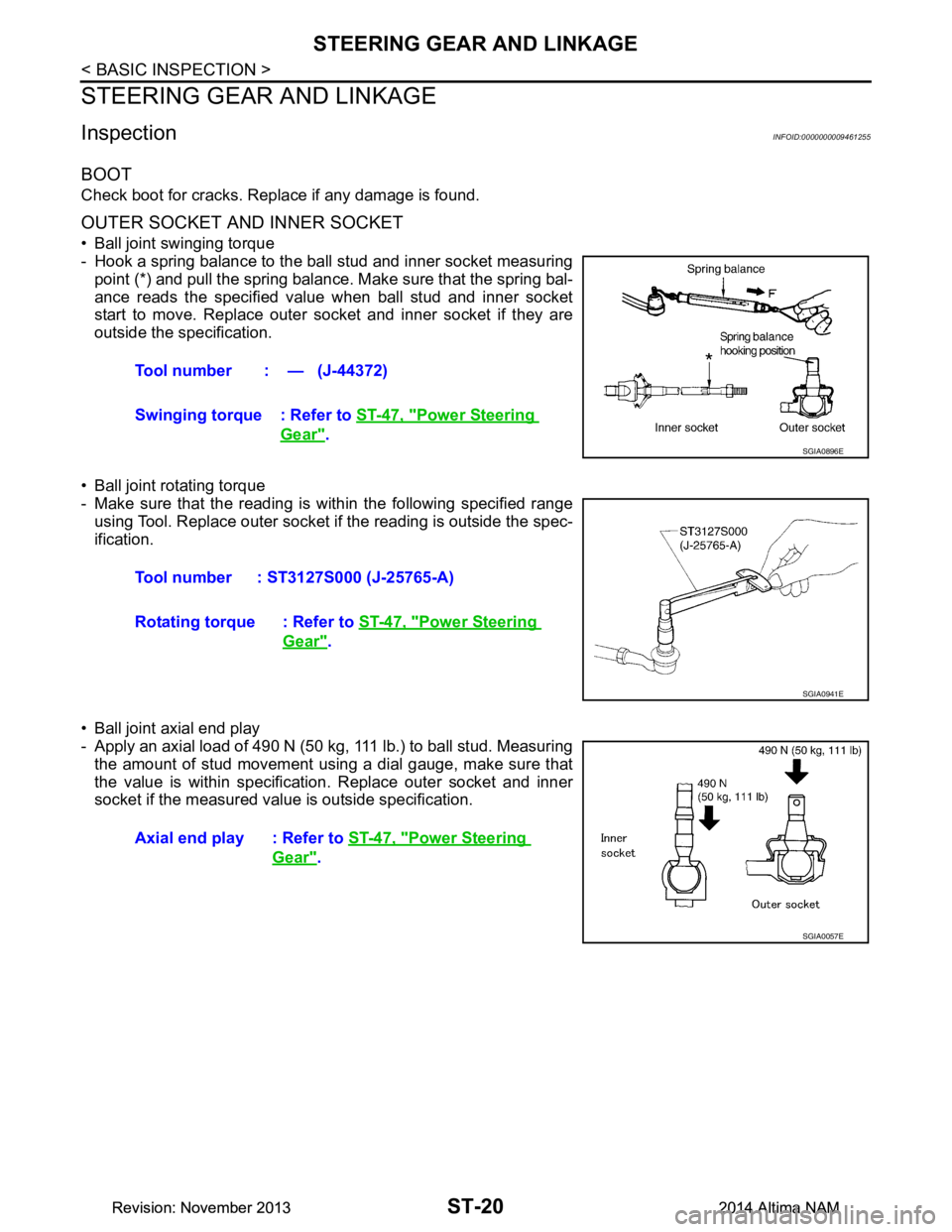
• Ball joint swinging torque
- Hook a spring balance to the ball stud and inner socket measuring point (*) and pull the spring balance. Make sure that the spring bal-
ance reads the specified value when ball stud and inner socket
start to move. Replace outer socket and inner socket if they are
outside the specification.
• Ball joint rotating torque
- Make sure that the reading is within the following specified range
using Tool. Replace outer socket if the reading is outside the spec-
ification.
• Ball joint axial end play
- Apply an axial load of 490 N (50 kg, 111 lb.) to ball stud. Measuring
the amount of stud movement using a dial gauge, make sure that
the value is within specificati on. Replace outer socket and inner
socket if the measured value is outside specification. Tool number : — (J-44372)
Swinging torque : Refer to ST-47, "Power Steering
Gear".SGIA0896E
Tool number : ST3127S000 (J-25765-A)
Rotating torque : Refer to ST-47, "Power Steering
Gear".
SGIA0941E
Axial end play : Refer to ST-47, "Power Steering
Gear".
SGIA0057E
Revision: November 20132014 Altima NAMRevision: November 20132014 Altima NAM
Page 4139 of 4801
ST-36
< REMOVAL AND INSTALLATION >
STEERING GEAR AND LINKAGE
STEERING GEAR AND LINKAGE
Exploded ViewINFOID:0000000009461272
Removal and InstallationINFOID:0000000009461273
NOTE:
When removing components such as hoses, tubes/lines, etc. , cap or plug openings to prevent fluid from spill-
ing.
REMOVAL
1. Remove the front wheels and tires using power tool. Refer to WT-55, "Adjustment".
2. Disconnect stabilizer connecting rods at st eering knuckles and reposition. Refer to FSU-19, "Exploded
View".
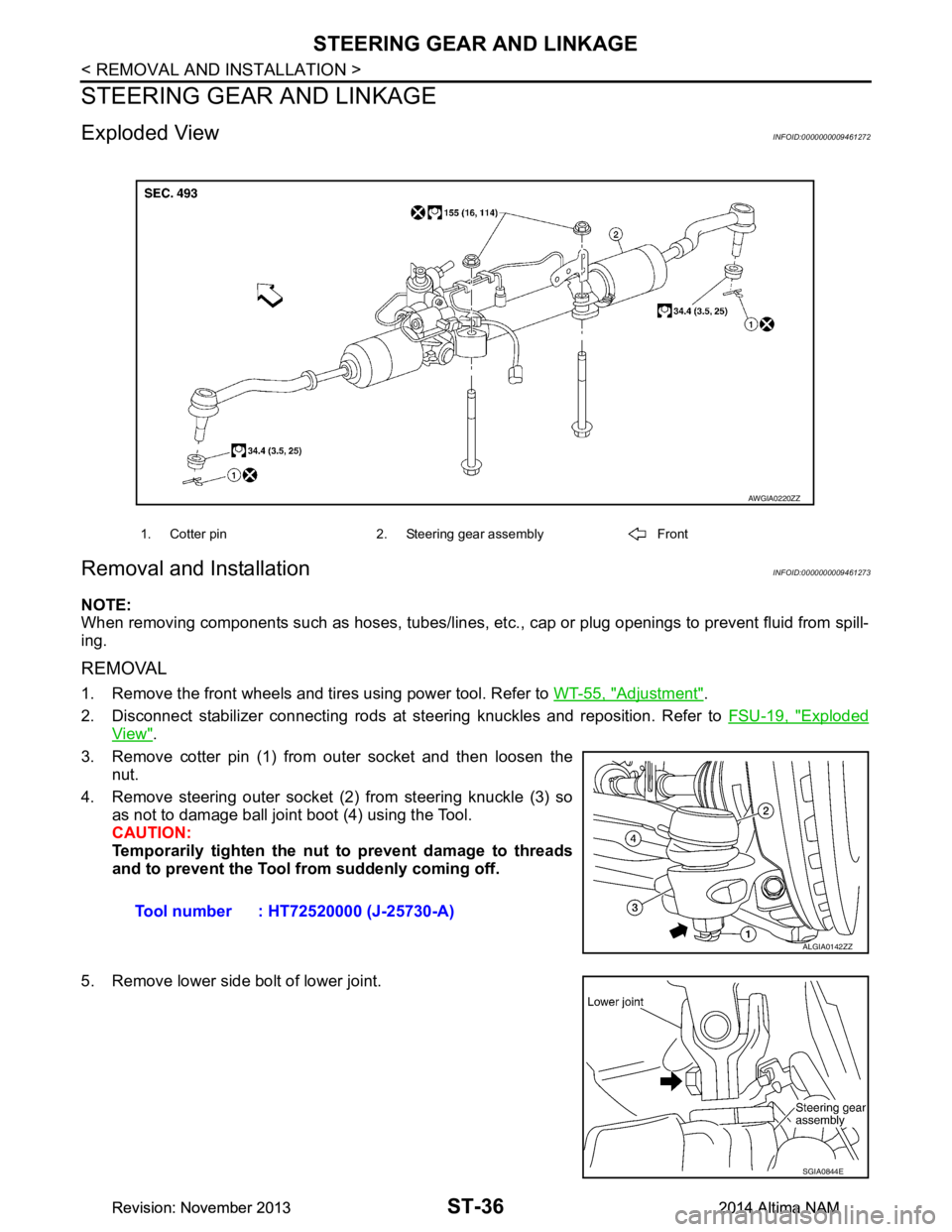
3. Remove cotter pin (1) from outer socket and then loosen the nut.
4. Remove steering outer socket (2) from steering knuckle (3) so as not to damage ball joint boot (4) using the Tool.
CAUTION:
Temporarily tighten the nut to prevent damage to threads
and to prevent the Tool fr om suddenly coming off.
5. Remove lower side bolt of lower joint.
1. Cotter pin 2. Steering gear assembly Front
AWGIA0220ZZ
Tool number : HT72520000 (J-25730-A)
ALGIA0142ZZ
SGIA0844E
Revision: November 20132014 Altima NAMRevision: November 20132014 Altima NAM
Page 4146 of 4801
STEERING GEAR AND LINKAGEST-43
< UNIT DISASSEMBLY AND ASSEMBLY >
C
D E
F
H I
J
K L
M A
B
ST
N
O P
UNIT DISASSEMBLY AND ASSEMBLY
STEERING GEAR AND LINKAGE
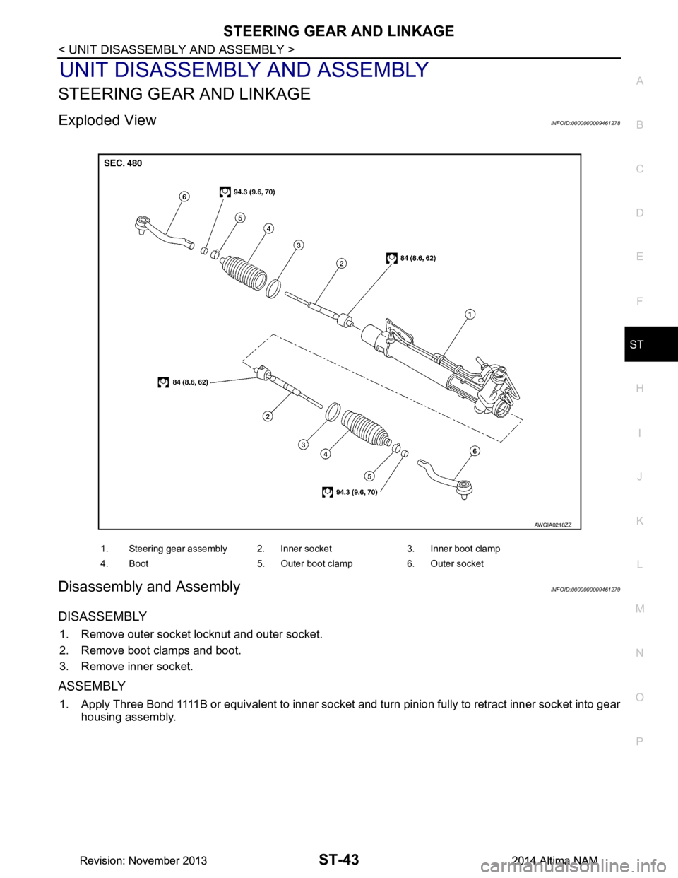
Exploded ViewINFOID:0000000009461278
Disassembly and AssemblyINFOID:0000000009461279
DISASSEMBLY
1. Remove outer socket locknut and outer socket.
2. Remove boot clamps and boot.
3. Remove inner socket.
ASSEMBLY
1. Apply Three Bond 1111B or equivalent to inner socket and turn pinion fully to retract inner socket into gear housing assembly.
1. Steering gear assembly 2. Inner socket 3. Inner boot clamp
4. Boot 5. Outer boot clamp 6. Outer socket
AWGIA0218ZZ
Revision: November 20132014 Altima NAMRevision: November 20132014 Altima NAM
Page 4147 of 4801
ST-44
< UNIT DISASSEMBLY AND ASSEMBLY >
STEERING GEAR AND LINKAGE
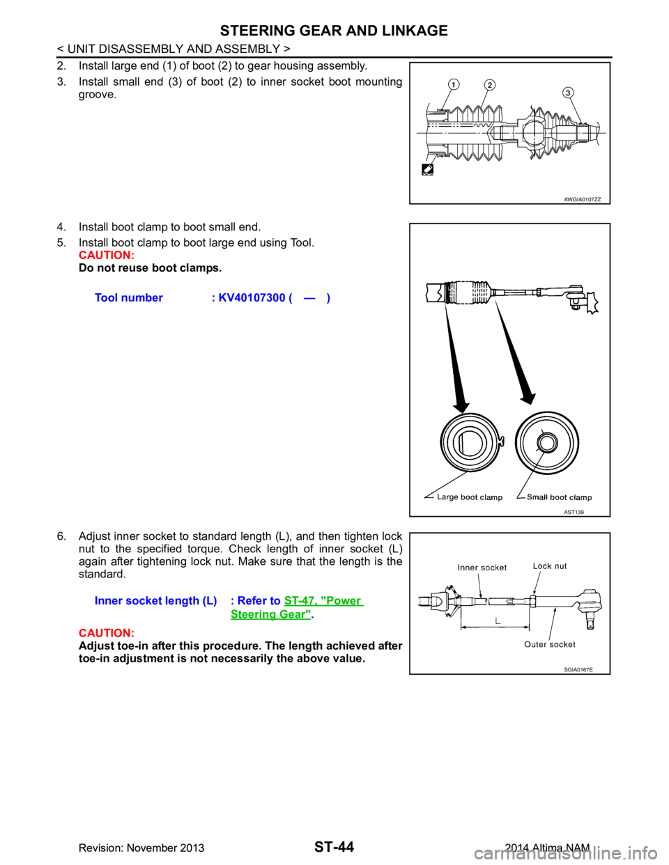
2. Install large end (1) of boot (2) to gear housing assembly.
3. Install small end (3) of boot (2) to inner socket boot mounting groove.
4. Install boot clamp to boot small end.
5. Install boot clamp to boot large end using Tool. CAUTION:
Do not reuse boot clamps.
6. Adjust inner socket to standard length (L), and then tighten lock nut to the specified torque. Check length of inner socket (L)
again after tightening lock nut. Make sure that the length is the
standard.
CAUTION:
Adjust toe-in after this proced ure. The length achieved after
toe-in adjustment is not necessarily the above value.
AWGIA0107ZZ
Tool number : KV40107300 ( — )
AST139
Inner socket length (L) : Refer to ST-47, "Power
Steering Gear".
SGIA0167E
Revision: November 20132014 Altima NAMRevision: November 20132014 Altima NAM
Page 4154 of 4801
PRECAUTIONSSTC-3
< PRECAUTION >
C
D E
F
H I
J
K L
M A
B
STC
N
O P
PRECAUTION
PRECAUTIONS
Precaution for Supplemental Restraint System (SRS) "AIR BAG" and "SEAT BELT
PRE-TENSIONER"
INFOID:0000000009951730
The Supplemental Restraint System such as “A IR BAG” and “SEAT BELT PRE-TENSIONER”, used along
with a front seat belt, helps to reduce the risk or severi ty of injury to the driver and front passenger for certain
types of collision. Information necessary to service t he system safely is included in the SR and SB section of
this Service Manual.
WARNING:
• To avoid rendering the SRS inoper ative, which could increase the risk of personal injury or death in
the event of a collision which would result in air bag inflation, all maintenance must be performed by
an authorized NISSAN/INFINITI dealer.
• Improper maintenance, including in correct removal and installation of the SRS, can lead to personal
injury caused by unintentional act ivation of the system. For removal of Spiral Cable and Air Bag
Module, see the SR section.
• Do not use electrical test equipm ent on any circuit related to the SRS unless instructed to in this
Service Manual. SRS wiring harnesses can be identi fied by yellow and/or orange harnesses or har-
ness connectors.
PRECAUTIONS WHEN USING POWER TOOLS (AIR OR ELECTRIC) AND HAMMERS
WARNING:
• When working near the Airbag Diagnosis Sensor Un it or other Airbag System sensors with the Igni-
tion ON or engine running, DO NOT use air or el ectric power tools or strike near the sensor(s) with a
hammer. Heavy vibration could activate the sensor( s) and deploy the air bag(s), possibly causing
serious injury.
• When using air or electric power tools or hammers , always switch the Ignition OFF, disconnect the
battery and wait at least three mi nutes before performing any service.
Service Notice and Precautions for Hydrau lic Pump Electric Power Steering System
INFOID:0000000009460340
• Check each tire for proper air pressure and size. Refer to WT-60, "Tire".
• Verify that the steering system components are G enuine NISSAN parts and have been installed properly.
• Check the steering column for loose mounting bolts.
• Check the steering gear assembly for loose mounting bolts. Check the inner sockets and outer sockets for
damage or wear. Inspect the boots and seals for leakage of power steering fluid.
• Verify proper wheel alignment. Refer to FSU-7, "Inspection and Adjustment"
.
• Check for any damage, wear, or modification to the suspension and body that would result in increased
weight or an improper wheelarch height. Refer to FSU-26, "Wheelarch Height (Unladen*
1)".
• Check for proper battery voltage.
• Verify that all power steering pump assembly connections are clean and fully seated.
• Verify that only Genuine NISSAN E-PSF is used. Use of any power steering fluid other than Genuine NIS-
SAN E-PSF will prevent the power st eering system from proper operation.
• An audible high pitch noise may be heard from the engine compartment when the steering wheel is oper-
ated, particularly at low speeds such as a parking lot maneuver. This condition is not a malfunction, rather
normal system operation. Steering at low speeds or parking lot maneuvers demands higher hydraulic assis-
tance, resulting in larger power st eering pump load and increased system noise.
• The power steering pump is electrically controlled by the power steering control module.
• Before connecting or disconnecting the power steeri ng control module harness connectors, turn ignition
switch “OFF” and disconnect battery ground cable. Batter y voltage is applied to power steering control mod-
ule even if ignition switch is turned “OFF”.
Revision: November 20132014 Altima NAMRevision: November 20132014 Altima NAM