Page 142 of 4801

BR-46
< UNIT DISASSEMBLY AND ASSEMBLY >
REAR DISC BRAKE
2. Place a wooden block in the brake caliper as shown, and blowair into the union bolt hole to the remove piston and piston boot.
WARNING:
Do not get fingers caught be tween the piston and wooden
block.
3. Remove the piston seal from the brake caliper using a suitable tool. Discard the piston seal.
CAUTION:
• Be careful not to damage the cylinder inner wall.
• Do not reuse the piston seal.
BRAKE CALIPER ASSEMBLY : In spection After DisassemblyINFOID:0000000009463726
BRAKE CALIPER
Check the inner wall of the cylinder for corrosion, wear, and damage. Replace as necessary.
CAUTION:
Clean the brake caliper using new br ake fluid. Do not use mineral oils such as gasoline or kerosene.
TORQUE MEMBER
Check the torque member for wear, cr acks, and damage. Replace as necessary.
PISTON
Check the piston surface for corrosion, wear, and damage. Replace as necessary.
CAUTION:
The piston sliding surface is plated . Do not polish with sandpaper.
SLIDING PIN BOLT, SLIDING PIN BOOT
Check the sliding pin bolt and sliding pin boot fo r wear, damage, and cracks. Replace as necessary.
BRAKE CALIPER ASSEMBLY : AssemblyINFOID:0000000009463727
CAUTION:
Use NISSAN Rubber Grease during assembly.
1. Apply rubber grease to new piston seal (1), and install on brake caliper.
CAUTION:
Do not reuse piston seal.
BRD0041D
JPFIA0038ZZ
JPFIA0039ZZ
Revision: November 20132014 Altima NAM
Page 143 of 4801
REAR DISC BRAKEBR-47
< UNIT DISASSEMBLY AND ASSEMBLY >
C
D E
G H
I
J
K L
M A
B
BR
N
O P
2. Apply rubber grease to new piston boot (1). Cover the piston (2) end with the new piston boot, and then install cylinder side lip on
new piston boot securely into a groove on brake caliper.
CAUTION:
Do not reuse piston boot.
3. Push piston (1) into caliper by hand and push piston boot (2) pis- ton side lip into the piston groove.
CAUTION:
Press the piston evenly and var y the pressing point to pre-
vent cylinder inner wall from being rubbed.
4. Using a suitable tool, secure piston boot with new retaining ring (1).
CAUTION:
• Make sure that boot is securely engaged in the groove on
brake caliper.
• Do not reuse retaining ring.
JPFIA0040ZZ
JPFIA0041ZZ
AWFIA0938ZZ
Revision: November 20132014 Altima NAM
Page 2453 of 4801

FAX-1
TRANSMISSION & DRIVELINE
CEF
G H
I
J
K L
M
SECTION FA X
A
B
FA X
N
O P
CONTENTS
FRONT AXLE
PRECAUTION ................ ...............................2
PRECAUTIONS .............................................. .....2
Precaution for Supplemental Restraint System
(SRS) "AIR BAG" and "SEAT BELT PRE-TEN-
SIONER" ............................................................. ......
2
Precautions for Drive Shaft .......................................2
PREPARATION ............................................3
PREPARATION .............................................. .....3
Special Service Tool ........................................... ......3
Commercial Service Tool ..........................................3
SYMPTOM DIAGNOSIS ...............................5
NOISE, VIBRATION, AND HARSHNESS
(NVH) TROUBLESHOOTING ........................ .....
5
NVH Troubleshooting Chart ................................ ......5
PERIODIC MAINTENANCE ..........................6
FRONT WHEEL HUB ..................................... .....6
Inspection ............................................................ ......6
FRONT DRIVE SHAFT ........................................7
Inspection ............................................................ ......7
REMOVAL AND INSTALLATION ................8
FRONT WHEEL HUB .........................................8
Exploded View ..................................................... .....8
Removal and Installation ..........................................8
FRONT DRIVE SHAFT .....................................10
Exploded View (LH) .................................................10
Removal and Installation (LH) .................................10
Exploded View (RH) ............................................ ....12
Removal and Installation (RH) .................................12
UNIT DISASSEMBLY AND ASSEMBLY ....15
FRONT DRIVE SHAFT .....................................15
Disassembly and Assembly (LH) ......................... ....15
Disassembly and Assembly (RH) ............................20
SERVICE DATA AND SPECIFICATIONS
(SDS) ............... .............................................
27
SERVICE DATA AND SPECIFICATIONS
(SDS) .................................................................
27
Wheel Bearing ..................................................... ....27
Drive Shaft ...............................................................27
Dynamic Damper .....................................................27
Boot Bands ..............................................................28
Revision: November 20132014 Altima NAM
Page 2455 of 4801
PREPARATIONFAX-3
< PREPARATION >
CEF
G H
I
J
K L
M A
B
FA X
N
O P
PREPARATION
PREPARATION
Special Service ToolINFOID:0000000009464434
The actual shapes of the tools may differ from those illustrated here.
Commercial Service ToolINFOID:0000000009464435
Tool number
(TechMate No.)
Tool name Description
KV38106700
(J-34296)
KV38106800
(J-34297)
Differential side oil seal protector Installing drive shaft
LH: KV38106700 (J-34296)
RH: KV38106800 (J-34297)
KV40107300
(—)
Boot Band crimping tool Installing boot bands
KV40107500
(—)
Drive shaft attachment Removing drive shaft
NT147
ZZA1229D
ZZA1230D
Tool name
Description
Drive shaft puller Removing drive shaft joint sub assembly
JPDIG0152ZZ
Revision: November 20132014 Altima NAM
Page 2459 of 4801
FRONT DRIVE SHAFTFAX-7
< PERIODIC MAINTENANCE >
CEF
G H
I
J
K L
M A
B
FA X
N
O P
FRONT DRIVE SHAFT
InspectionINFOID:0000000009464437
• Check drive shaft mounting point and joint for looseness and other damage.
• Check boot for cracks and other damage. CAUTION:
Replace entire drive shaft assembly when noi se or vibration occur from drive shaft.
Revision: November 20132014 Altima NAM
Page 2467 of 4801
FRONT DRIVE SHAFTFAX-15
< UNIT DISASSEMBLY AND ASSEMBLY >
CEF
G H
I
J
K L
M A
B
FA X
N
O P
UNIT DISASSEMBLY AND ASSEMBLY
FRONT DRIVE SHAFT
Disassembly and Assembly (LH)INFOID:0000000009464444
DISASSEMBLY
Transaxle Side
1. Mount front drive shaft in a vise. CAUTION:
When mounting shaft in a vise, always use copper or alum inum plates between vise and shaft.
2. Remove boot bands and slide the boot back.
3. Remove circlip and dust shield from slide joint housing.
4. Put matching marks on slide joint housing and shaft before separating joint assembly.
5. Remove stopper ring with a suitable tool, then pull out slide joint housing.
1. Circlip 2. Dust shield 3. Slide joint housing
4. Snap ring 5. Spider assembly 6. Stopper ring
7. Boot band 8. Boot 9. Shaft
10. Damper band 11. Damper 12. Boot band
13. Boot 14. Ball cage / Steel ball / Inner race assembly 15. Circlip
16. Joint sub-assembly Front
AWDIA0896ZZ
SFA476
Revision: November 20132014 Altima NAM
Page 2468 of 4801

FAX-16
< UNIT DISASSEMBLY AND ASSEMBLY >
FRONT DRIVE SHAFT
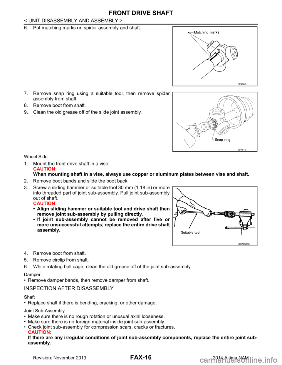
6. Put matching marks on spider assembly and shaft.
7. Remove snap ring using a suitable tool, then remove spider assembly from shaft.
8. Remove boot from shaft.
9. Clean the old grease off of the slide joint assembly.
Wheel Side
1. Mount the front drive shaft in a vise. CAUTION:
When mounting shaf t in a vise, always use copper or al uminum plates between vise and shaft.
2. Remove boot bands and slide the boot back.
3. Screw a sliding hammer or suitable tool 30 mm (1.18 in) or more into threaded part of joint sub-assembly. Pull joint sub-assembly
out of shaft.
CAUTION:
• Align sliding hammer or suitab le tool and drive shaft then
remove joint sub-assembly by pulling directly.
• If joint sub-assembly cannot be removed after five or more unsuccessful attempts, replace the entire drive shaft
assembly.
4. Remove boot from shaft.
5. Remove circlip from shaft.
6. While rotating ball cage, clean the old grease off of the joint sub-assembly.
Damper
• Remove damper bands, then remove damper from shaft.
INSPECTION AFTER DISASSEMBLY
Shaft
• Replace shaft if there is bending, cracking, or other damage.
Joint Sub-Assembly
• Make sure there is no rough rotation or unusual axial looseness.
• Make sure there is no foreign material inside joint sub-assembly.
• Check joint sub-assembly for compression scars, cracks or fractures. CAUTION:
If there are any irregular conditions of joint sub-assembly components, replace the entire joint sub-
assembly.
SFA963
SFA612
SDIA0606E
Revision: November 20132014 Altima NAM
Page 2469 of 4801

FRONT DRIVE SHAFTFAX-17
< UNIT DISASSEMBLY AND ASSEMBLY >
CEF
G H
I
J
K L
M A
B
FA X
N
O P
Slide Joint Housing
• Make sure there are no compression scars, cracks or
fractures or unusual wear of ball rolling surface.
• Make sure there is no damage to shaft screws.
• Make sure there is no deformation of boot installation parts.
Ball Cage
• Make sure there are no compression scars, cracks, fractures of sliding surface.
Steel Ball
• Make sure there are no compression scars , cracks, fractures or unusual wear.
Inner Race
• Check ball sliding surface for compression scars, cracks or fractures.
• Make sure there is no damage to serrated part.
CAUTION:
If there are any irregular condit ions in the component, replace with a new set of joint sub-assembly,
ball cage, steel ball and inner race.
Damper
• Check damper for cracks or wear. Install damper with new damper bands.
ASSEMBLY
Transaxle Side
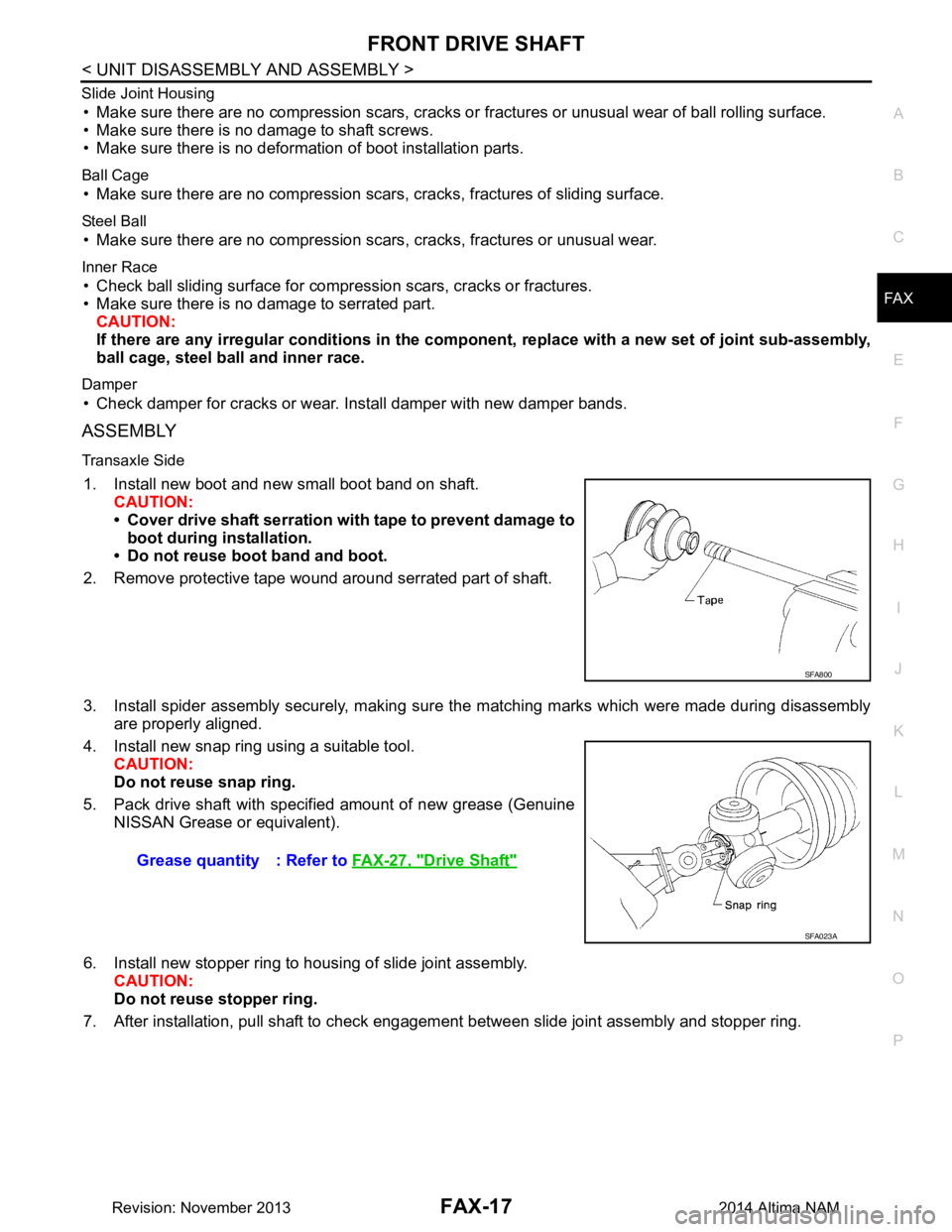
1. Install new boot and new small boot band on shaft.
CAUTION:
• Cover drive shaft serration with tape to prevent damage to boot during installation.
• Do not reuse boot band and boot.
2. Remove protective tape wound around serrated part of shaft.
3. Install spider assembly securely, making sure the matching marks which were made during disassembly are properly aligned.
4. Install new snap ring using a suitable tool. CAUTION:
Do not reuse snap ring.
5. Pack drive shaft with specified amount of new grease (Genuine NISSAN Grease or equivalent).
6. Install new stopper ring to housing of slide joint assembly. CAUTION:
Do not reuse stopper ring.
7. After installation, pull shaft to check engagement between slide joint assembly and stopper ring.
SFA800
Grease quantity : Refer to FAX-27, "Drive Shaft"
SFA023A
Revision: November 20132014 Altima NAM