2014 NISSAN TEANA ECU
[x] Cancel search: ECUPage 2523 of 4801
FSU-22
< UNIT DISASSEMBLY AND ASSEMBLY >
FRONT COIL SPRING AND STRUT
UNIT DISASSEMBLY AND ASSEMBLY
FRONT COIL SPRING AND STRUT
Disassembly and AssemblyINFOID:0000000009460638
DISASSEMBLY
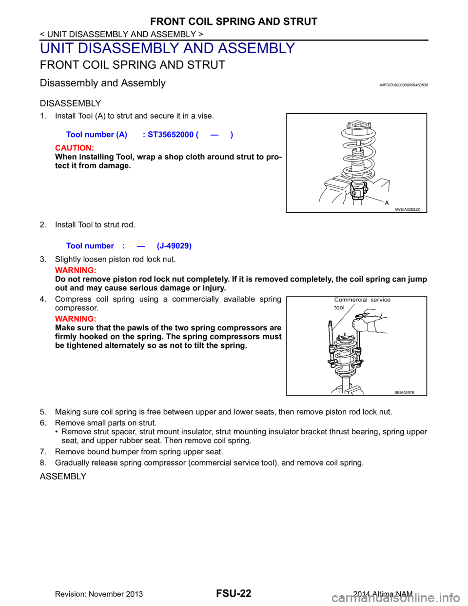
1. Install Tool (A) to strut and secure it in a vise.CAUTION:
When installing Tool, wrap a sh op cloth around strut to pro-
tect it from damage.
2. Install Tool to strut rod.
3. Slightly loosen piston rod lock nut. WARNING:
Do not remove piston rod lock nut completely. If it is removed completely, the coil spring can jump
out and may cause serious damage or injury.
4. Compress coil spring using a commercially available spring compressor.
WARNING:
Make sure that the pawls of the two spring compressors are
firmly hooked on the spring. The spring compressors must
be tightened alternately so as not to tilt the spring.
5. Making sure coil spring is free between upper and lower seats, then remove piston rod lock nut.
6. Remove small parts on strut. • Remove strut spacer, strut mount insulator, strut mounting insulator bracket thrust bearing, spring upper
seat, and upper rubber seat. Then remove coil spring.
7. Remove bound bumper from spring upper seat.
8. Gradually release spring compressor (commercial service tool), and remove coil spring.
ASSEMBLY
Tool number (A) : ST35652000 ( — )
AWEIA0262ZZ
Tool number : — (J-49029)
SEIA0297E
Revision: November 20132014 Altima NAM
Page 2524 of 4801
FRONT COIL SPRING AND STRUTFSU-23
< UNIT DISASSEMBLY AND ASSEMBLY >
C
D
F
G H
I
J
K L
M A
B
FSU
N
O P
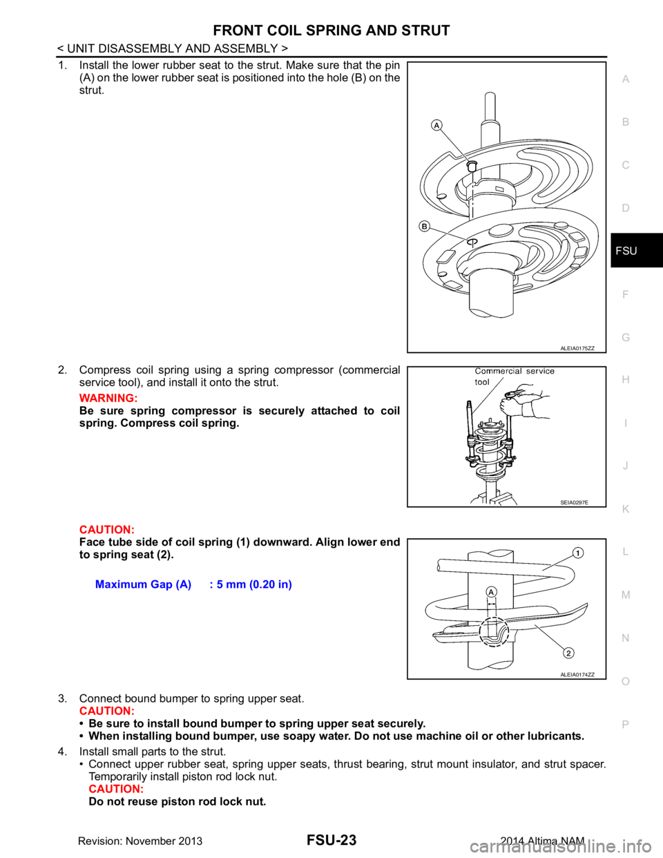
1. Install the lower rubber seat to the strut. Make sure that the pin (A) on the lower rubber seat is positioned into the hole (B) on the
strut.
2. Compress coil spring using a spring compressor (commercial service tool), and install it onto the strut.
WARNING:
Be sure spring compressor is securely attached to coil
spring. Compress coil spring.
CAUTION:
Face tube side of coil spring (1) downward. Align lower end
to spring seat (2).
3. Connect bound bumper to spring upper seat. CAUTION:
• Be sure to install bound bump er to spring upper seat securely.
• When installing bound bumper, use soapy water. Do not use machine oil or other lubricants.
4. Install small parts to the strut. • Connect upper rubber seat, spring upper seats, thrust bearing, strut mount insulator, and strut spacer.
Temporarily install piston rod lock nut.
CAUTION:
Do not reuse piston rod lock nut.
ALEIA0175ZZ
SEIA0297E
Maximum Gap (A) : 5 mm (0.20 in)
ALEIA0174ZZ
Revision: November 20132014 Altima NAM
Page 2555 of 4801
PRECAUTIONSGI-27
< PRECAUTION >
C
D E
F
G H
I
J
K L
M B
GI
N
O P
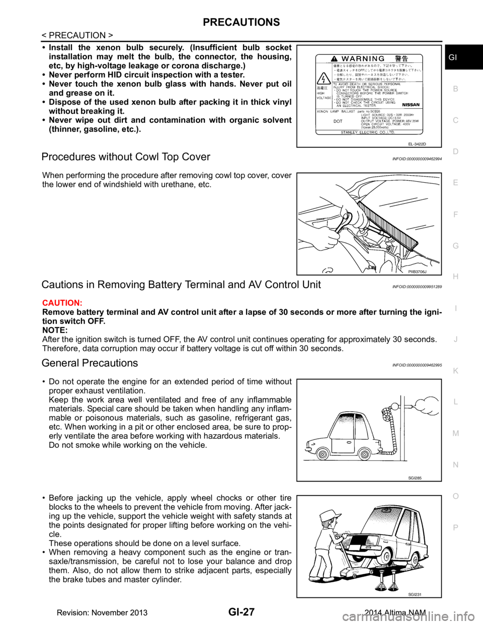
• Install the xenon bulb secure ly. (Insufficient bulb socket
installation may melt the bu lb, the connector, the housing,
etc, by high-voltage leakage or corona discharge.)
• Never perform HID circuit inspection with a tester.
• Never touch the xenon bulb gl ass with hands. Never put oil
and grease on it.
• Dispose of the used xenon bulb after packing it in thick vinyl
without breaking it.
• Never wipe out dirt and contam ination with organic solvent
(thinner, gasoline, etc.).
Procedures without Cowl Top CoverINFOID:0000000009462994
When performing the procedure after removing cowl top cover, cover
the lower end of windshield with urethane, etc.
Cautions in Removing Battery Terminal and AV Control UnitINFOID:0000000009951289
CAUTION:
Remove battery terminal and AV control unit after a lapse of 30 seconds or more after turning the igni-
tion switch OFF.
NOTE:
After the ignition switch is turned OFF, the AV cont rol unit continues operating for approximately 30 seconds.
Therefore, data corruption may occur if battery voltage is cut off within 30 seconds.
General PrecautionsINFOID:0000000009462995
• Do not operate the engine for an extended period of time without proper exhaust ventilation.
Keep the work area well ventilated and free of any inflammable
materials. Special care should be taken when handling any inflam-
mable or poisonous materials, such as gasoline, refrigerant gas,
etc. When working in a pit or ot her enclosed area, be sure to prop-
erly ventilate the area before working with hazardous materials.
Do not smoke while working on the vehicle.
• Before jacking up the vehicle, apply wheel chocks or other tire blocks to the wheels to prevent t he vehicle from moving. After jack-
ing up the vehicle, support the vehicle weight with safety stands at
the points designated for proper lifting before working on the vehi-
cle.
These operations should be done on a level surface.
• When removing a heavy component such as the engine or tran-
saxle/transmission, be careful not to lose your balance and drop
them. Also, do not allow them to strike adjacent parts, especially
the brake tubes and master cylinder.
EL-3422D
PIIB3706J
SGI285
SGI231
Revision: November 20132014 Altima NAMRevision: November 20132014 Altima NAM
Page 2558 of 4801
GI-30
< PRECAUTION >
PRECAUTIONS
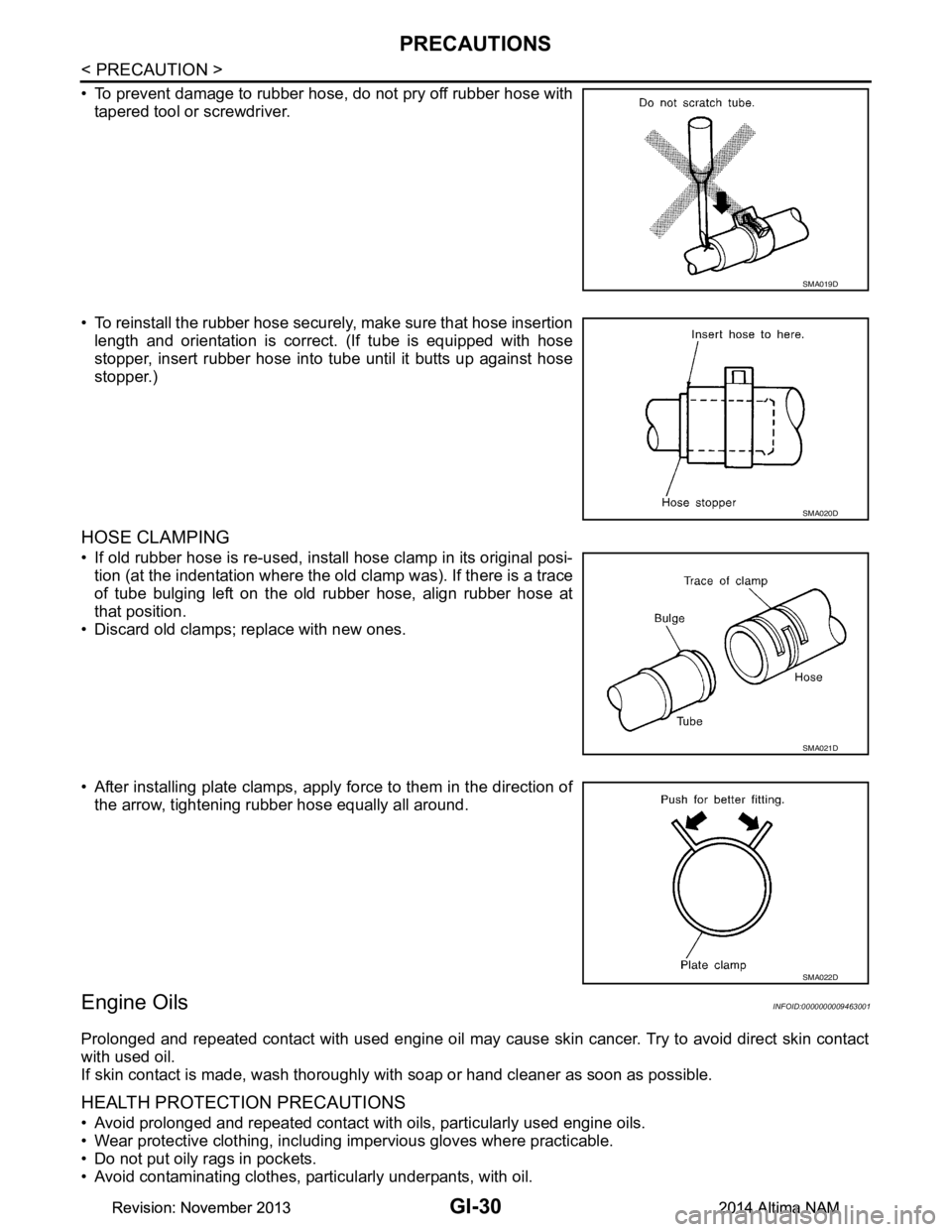
• To prevent damage to rubber hose, do not pry off rubber hose withtapered tool or screwdriver.
• To reinstall the rubber hose securely, make sure that hose insertion length and orientation is correct. (If tube is equipped with hose
stopper, insert rubber hose into tube until it butts up against hose
stopper.)
HOSE CLAMPING
• If old rubber hose is re-used, install hose clamp in its original posi- tion (at the indentation where the old clamp was). If there is a trace
of tube bulging left on the old rubber hose, align rubber hose at
that position.
• Discard old clamps; replace with new ones.
• After installing plate clamps, apply force to them in the direction of the arrow, tightening rubber hose equally all around.
Engine OilsINFOID:0000000009463001
Prolonged and repeated contact with used engine oil may cause skin cancer. Try to avoid direct skin contact
with used oil.
If skin contact is made, wash thoroughly with soap or hand cleaner as soon as possible.
HEALTH PROTECTION PRECAUTIONS
• Avoid prolonged and repeated contact with oils, particularly used engine oils.
• Wear protective clothing, including impervious gloves where practicable.
• Do not put oily rags in pockets.
• Avoid contaminating clothes, pa rticularly underpants, with oil.
SMA019D
SMA020D
SMA021D
SMA022D
Revision: November 20132014 Altima NAMRevision: November 20132014 Altima NAM
Page 2576 of 4801
GI-48
< BASIC INSPECTION >
SERVICE INFORMATION FOR ELECTRICAL INCIDENT
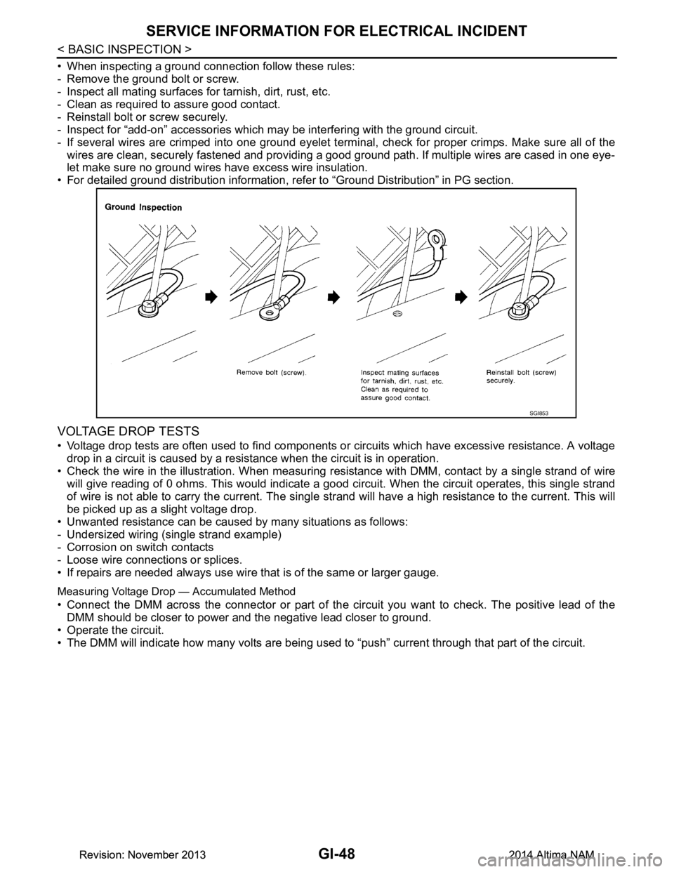
• When inspecting a ground connection follow these rules:
- Remove the ground bolt or screw.
- Inspect all mating surfaces for tarnish, dirt, rust, etc.
- Clean as required to assure good contact.
- Reinstall bolt or screw securely.
- Inspect for “add-on” accessories which may be interfering with the ground circuit.
- If several wires are crimped into one ground eyelet termi nal, check for proper crimps. Make sure all of the
wires are clean, securely fastened and providing a good ground path. If multiple wires are cased in one eye-
let make sure no ground wires have excess wire insulation.
• For detailed ground distribution information, re fer to “Ground Distribution” in PG section.
VOLTAGE DROP TESTS
• Voltage drop tests are often used to find components or circuits which have excessive resistance. A voltage
drop in a circuit is caused by a resistance when the circuit is in operation.
• Check the wire in the illustration. When measuring re sistance with DMM, contact by a single strand of wire
will give reading of 0 ohms. This would indicate a good circuit. When the circuit operates, this single strand
of wire is not able to carry the current. The single st rand will have a high resistance to the current. This will
be picked up as a slight voltage drop.
• Unwanted resistance can be caused by many situations as follows:
- Undersized wiring (single strand example)
- Corrosion on switch contacts
- Loose wire connections or splices.
• If repairs are needed always use wire that is of the same or larger gauge.
Measuring Voltage Drop — Accumulated Method
• Connect the DMM across the connector or part of the ci rcuit you want to check. The positive lead of the
DMM should be closer to power and the negative lead closer to ground.
• Operate the circuit.
• The DMM will indicate how many volts are being used to “push” current through that part of the circuit.
SGI853
Revision: November 20132014 Altima NAMRevision: November 20132014 Altima NAM
Page 2579 of 4801
CONSULT CHECKING SYSTEMGI-51
< BASIC INSPECTION >
C
D E
F
G H
I
J
K L
M B
GI
N
O PCONSULT CHECKING SYSTEM
DescriptionINFOID:0000000009463016
CAUTION:
After disconnecting the CONSULT vehicle interface (VI) from the data link connector, the ignition must
be cycled OFF → ON (for at least 5 seconds) → OFF. If this step is not performed, the BCM may not go
to “sleep mode”, potentiall y causing a discharged battery and a no-start condition.
NOTE:
This vehicle is diagnosed using the CONSULT-III plus.
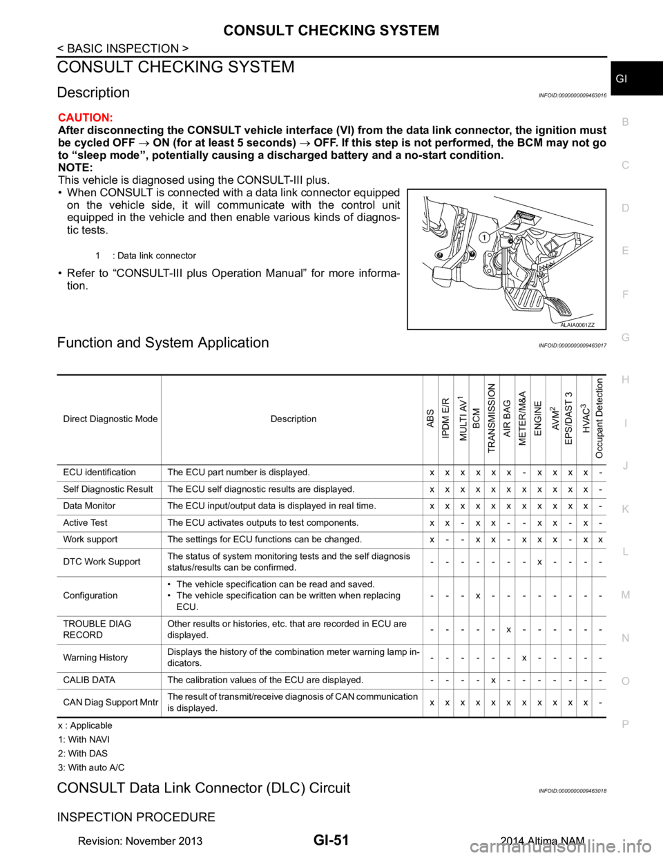
• When CONSULT is connected with a data link connector equipped on the vehicle side, it will communicate with the control unit
equipped in the vehicle and then enable various kinds of diagnos-
tic tests.
• Refer to “CONSULT-III plus Operation Manual” for more informa- tion.
Function and System ApplicationINFOID:0000000009463017
x : Applicable
1: With NAVI
2: With DAS
3: With auto A/C
CONSULT Data Link Connector (DLC) CircuitINFOID:0000000009463018
INSPECTION PROCEDURE
1 : Data link connector
ALAIA0061ZZ
Direct Diagnostic Mode DescriptionABS
IPDM E/R
MULTI AV
1
BCM
TRANSMISSION
AIR BAG
METER/M&A
ENGINE
AV M
2
EPS/DAST 3 HVAC
3
Occupant Detection
ECU identification The ECU part number is displayed. x x x x x x - x x x x -
Self Diagnostic Result The ECU self diagnostic results are displayed. x x x x x x x x x x x -
Data Monitor The ECU input/output data is displayed in real time. x x x x x x x x x x x -
Active Test The ECU activates outputs to test components. x x - x x - - x x - x -
Work support The settings for ECU functions can be changed. x - - x x - x x x - x x
DTC Work Support The status of system monitoring tests and the self diagnosis
status/results can be confirmed. -------x----
Configuration • The vehicle specification can be read and saved.
• The vehicle specification can be written when replacing ECU. ---x--------
TROUBLE DIAG
RECORD Other results or histories, etc. that are recorded in ECU are
displayed. -----x------
Warning History Displays the history of the combination meter warning lamp in-
dicators. ------x-----
CALIB DATA The calibration values of the ECU are displayed. - - - - x - - - - - - -
CAN Diag Support Mntr The result of transmit/receive diagnosis of CAN communication
is displayed. xxxxxxxxxxx-
Revision: November 20132014 Altima NAMRevision: November 20132014 Altima NAM
Page 2581 of 4801
GW-1
BODY EXTERIOR, DOORS, ROOF & VEHICLE SECURITY
C
D E
F
G H
I
J
L
M
SECTION GW
A
B
GW
N
O P
CONTENTS
GLASS & WINDOW SYSTEM
PRECAUTION ................ ...............................2
PRECAUTIONS .............................................. .....2
Precaution for Supplemental Restraint System
(SRS) "AIR BAG" and "SEAT BELT PRE-TEN-
SIONER" ............................................................. ......
2
Procedure without Cowl Top Cover .......................2
Handling for Adhesive and Primer ............................2
Precaution for Work ..................................................2
PREPARATION ............................................4
PREPARATION .............................................. .....4
Special Service Tools ........................................ ......4
Commercial Service Tools .......................................4
SYMPTOM DIAGNOSIS ...............................5
SQUEAK AND RATTLE TROUBLE DIAG-
NOSES ........................................................... .....
5
Work Flow ........................................................... ......5
Generic Squeak and Rattle Troubleshooting ............6
Diagnostic Worksheet ...............................................9
REMOVAL AND INSTALLATION ...............11
WINDSHIELD GLASS .................................... ....11
Exploded View .................................................... ....11
Removal and Installation .........................................12
FRONT DOOR GLASS .....................................14
Removal and Installation ..................................... ....14
Inspection and Adjustment ......................................15
FRONT REGULATOR .......................................16
Exploded View .........................................................16
Removal and Installation - Front Regulator .............16
Inspection and Adjustment .................................. ....18
Removal and Installation - Front Power Window
Motor ................................................................... ....
18
REAR DOOR GLASS .......................................19
Removal and Installation .........................................19
REAR REGULATOR .........................................20
Exploded View .........................................................20
Removal and Installation - Rear Regulator ..............20
Removal and Installation - Rear Power Window
Motor ................................................................... ....
22
SIDE WINDOW GLASS ....................................23
Components ............................................................23
Removal and Installation .........................................23
REAR WINDOW GLASS ..................................25
Exploded View .........................................................25
Removal and Installation .........................................25
Revision: November 20132014 Altima NAM
Page 2583 of 4801
PRECAUTIONSGW-3
< PRECAUTION >
C
D E
F
G H
I
J
L
M A
B
GW
N
O P
• When removing (disengaging) components with a screwdriver or similar tool, be sure to wrap the component with a shop cloth or vinyl tape to protect it.
• Protect the removed parts with a shop cloth and prevent them from being dropped.
• Replace a deformed or damaged clip.
• If a part is specified as a non-reusabl e part, always replace it with a new one.
• Be sure to tighten bolts and nuts securely to the specified torque.
• After installation is complete, be sure to check that each part works properly.
• Follow the steps below to clean components:
- Water soluble dirt:
• Dip a soft cloth into lukewarm water, wring the water out of the cloth and wipe the dirty area.
• Then rub with a soft, dry cloth.
-Oily dirt:
• Dip a soft cloth into lukewarm water with mild detergent (concentration: within 2 to 3%) and wipe the dirty
area.
• Then dip a cloth into fresh water, wring the water out of the cloth and wipe the detergent off.
• Then rub with a soft, dry cloth.
- Do not use organic solvent such as thinner, benzene, alcohol or gasoline.
- For genuine leather seats, use a genuine leather seat cleaner.
Revision: November 20132014 Altima NAM