Page 4728 of 4801

ROAD WHEELWT-53
< PERIODIC MAINTENANCE >
C
D
F
G H
I
J
K L
M A
B
WT
N
O P
PERIODIC MAINTENANCE
ROAD WHEEL
InspectionINFOID:0000000009464520
ALUMINUM WHEEL
1. Check tires for wear and improper inflation.
2. Check wheels for deformation, cracks and other damage. If deformed, remove wheel and check wheel
runout.
3. Remove tire from aluminum wheel and mount wheel on a tire balance machine.
CAUTION:
DO NOT use center hole cone-type clamping machines to
hold the wheel assembly during tire removal/installation or
balancing. Damage to the wheel finish, cladding or chrome
may occur. Use only rim-type or universal lug-type clamp-
ing machines to hold the wheel assembly.
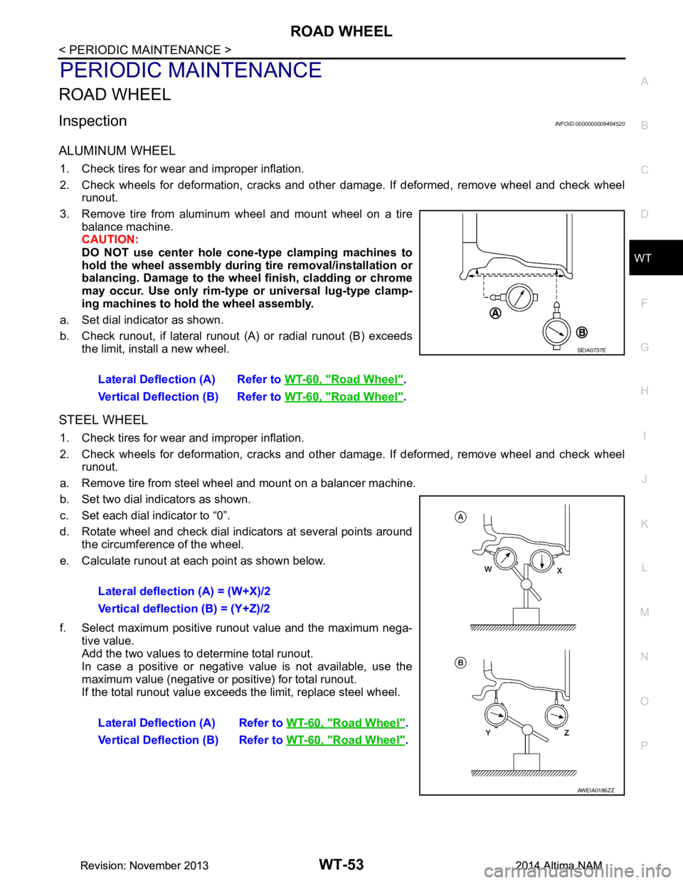
a. Set dial indicator as shown.
b. Check runout, if lateral runout (A) or radial runout (B) exceeds
the limit, install a new wheel.
STEEL WHEEL
1. Check tires for wear and improper inflation.
2. Check wheels for deformation, cracks and other damage. If deformed, remove wheel and check wheel
runout.
a. Remove tire from steel wheel and mount on a balancer machine.
b. Set two dial indicators as shown.
c. Set each dial indicator to “0”.
d. Rotate wheel and check dial indicators at several points around the circumference of the wheel.
e. Calculate runout at each point as shown below.
f. Select maximum positive runout value and the maximum nega- tive value.
Add the two values to determine total runout.
In case a positive or negative value is not available, use the
maximum value (negative or positive) for total runout.
If the total runout value exceeds the limit, replace steel wheel.
Lateral Deflection (A) Refer to
WT-60, "Road Wheel"
.
Vertical Deflection (B) Refer to WT-60, "Road Wheel"
.
SEIA0737E
Lateral deflection (A) = (W+X)/2
Vertical deflection (B) = (Y+Z)/2
Lateral Deflection (A) Refer to WT-60, "Road Wheel"
.
Vertical Deflection (B) Refer to WT-60, "Road Wheel"
.
AWEIA0186ZZ
Revision: November 20132014 Altima NAMRevision: November 20132014 Altima NAM
Page 4732 of 4801

TIRE PRESSURE SENSORWT-57
< UNIT REMOVAL AND INSTALLATION >
C
D
F
G H
I
J
K L
M A
B
WT
N
O P
UNIT REMOVAL AND INSTALLATION
TIRE PRESSURE SENSOR
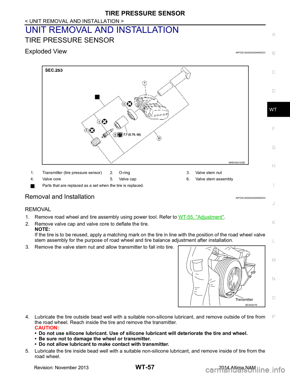
Exploded ViewINFOID:0000000009464523
Removal and InstallationINFOID:0000000009464524
REMOVAL
1. Remove road wheel and tire assembly using power tool. Refer to WT-55, "Adjustment".
2. Remove valve cap and valve core to deflate the tire. NOTE:
If the tire is to be reused, apply a matching mark on t he tire in line with the position of the road wheel valve
stem assembly for the purpose of road wheel and tire balance adjustment after installation.
3. Remove the valve stem nut and allow transmitter to fall into tire.
4. Lubricate the tire outside bead well with a suitable non-silicone lubricant, and remove outside of tire from the road wheel. Reach inside the ti re and remove the transmitter.
CAUTION:
• Do not use silicone lubricant. Use of silicone lubricant will deteriorate the tire and wheel.
• Be sure not to damage the wheel or transmitter.
• Do not allow lubricant to make contact with transmitter.
5. Lubricate the tire inside bead well with a suitable non-silicone lubricant, and remove inside of tire from the road wheel.
1. Transmitter (tire pressure sensor) 2. O-ring 3. Valve stem nut
4. Valve core 5. Valve cap 6. Valve stem assembly
: Parts that are replaced as a set when the tire is replaced.
AWEIA0212GB
SEIA0047E
Revision: November 20132014 Altima NAMRevision: November 20132014 Altima NAM
Page 4734 of 4801

TIRE PRESSURE SENSORWT-59
< UNIT REMOVAL AND INSTALLATION >
C
D
F
G H
I
J
K L
M A
B
WT
N
O P
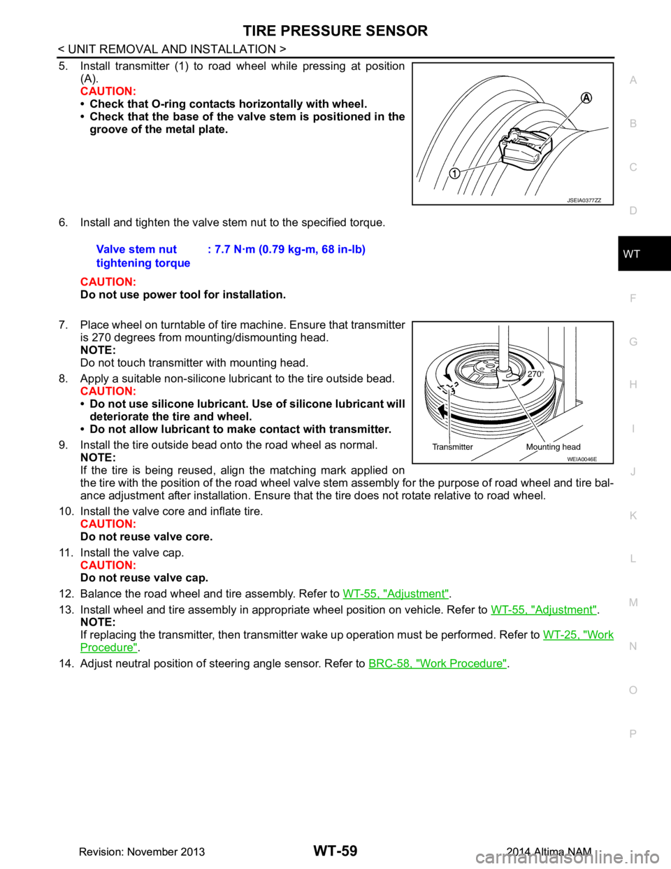
5. Install transmitter (1) to road wheel while pressing at position (A).
CAUTION:
• Check that O-ring contacts horizontally with wheel.
• Check that the base of the valve stem is positioned in the
groove of the metal plate.
6. Install and tighten the valve stem nut to the specified torque. CAUTION:
Do not use power tool for installation.
7. Place wheel on turntable of tire machine. Ensure that transmitter
is 270 degrees from mounting/dismounting head.
NOTE:
Do not touch transmitter with mounting head.
8. Apply a suitable non-silicone lubricant to the tire outside bead. CAUTION:
• Do not use silicone lubricant. Use of silicone lubricant will
deteriorate the tire and wheel.
• Do not allow lubricant to make contact with transmitter.
9. Install the tire outside bead onto the road wheel as normal. NOTE:
If the tire is being reused, align the matching mark applied on
the tire with the position of the road wheel valve st em assembly for the purpose of road wheel and tire bal-
ance adjustment after installation. Ensure that the tire does not rotate relative to road wheel.
10. Install the valve core and inflate tire. CAUTION:
Do not reuse valve core.
11. Install the valve cap. CAUTION:
Do not reuse valve cap.
12. Balance the road wheel and tire assembly. Refer to WT-55, "Adjustment"
.
13. Install wheel and tire assembly in appropriate wheel position on vehicle. Refer to WT-55, "Adjustment"
.
NOTE:
If replacing the transmitter, then transmitter wake up operation must be performed. Refer to WT-25, "Work
Procedure".
14. Adjust neutral position of steering angle sensor. Refer to BRC-58, "Work Procedure"
.
JSEIA0377ZZ
Valve stem nut
tightening torque : 7.7 N·m (0.79 kg-m, 68 in-lb)
WEIA0046E
Revision: November 20132014 Altima NAMRevision: November 20132014 Altima NAM