2014 NISSAN TEANA checking oil
[x] Cancel search: checking oilPage 3186 of 4801

MA-2
OIL FILTER : Removal and Installation ..................27
SPARK PLUG ........................................................ ...28
SPARK PLUG : Removal and Installation ..............29
EVAP VAPOR LINES ............................................. ...30
EVAP VAPOR LINES : Inspection ..........................30
CHASSIS AND BODY MAINTENANCE ......... ...31
IN-CABIN MICROFILTER ...................................... ...31
IN-CABIN MICROFILTER : Removal and Installa-
tion ....................................................................... ...
31
EXHAUST SYSTEM ............................................... ...31
EXHAUST SYSTEM : Checking Exhaust System ...31
CVT FLUID ............................................................. ...31
CVT FLUID : RE0F10D ..........................................32
CVT FLUID : Inspection ..........................................32
CVT FLUID : Replacement .....................................32
CVT FLUID : Adjustment ........................................34
CVT FLUID : RE0F10E ..........................................35
CVT FLUID : Inspection ..........................................35
CVT FLUID : Replacement .....................................35
CVT FLUID : Adjustment ........................................37
WHEELS ................................................................ ...38
WHEELS : Inspection .............................................38
WHEELS : Adjustment ...........................................39
BRAKE FLUID LEVEL AND LEAKS ........................40
BRAKE FLUID LEVEL AND LEAKS : Inspection ...40
BRAKE LINES AND CABLES ............................... ...41
BRAKE LINES AND CABLES : Inspection .............41
BRAKE FLUID ........................................................ ...41
BRAKE FLUID : Drain and Refill .............................41
DISC BRAKE .......................................................... ...42
DISC BRAKE : Front Brake Pad .............................42
DISC BRAKE : Inspection .......................................42
DISC BRAKE : Front Brake Rotor ...........................42
DISC BRAKE : Inspection .......................................42
DISC BRAKE : Rear Brake Pad ..............................43
DISC BRAKE : Inspection .......................................43
DISC BRAKE : Rear Brake Rotor ...........................43
DISC BRAKE : Inspection .......................................43
STEERING GEAR AND LINKAGE ........................ ...43
STEERING GEAR AND LINKAGE : Inspection ......43
POWER STEERING FLUID AND LINES ............... ...43
POWER STEERING FLUID AND LINES : Inspec-
tion ....................................................................... ...
44
AXLE AND SUSPENSION PARTS ........................ ...44
AXLE AND SUSPENSION PARTS : Inspection .....44
DRIVE SHAFT ........................................................ ...45
DRIVE SHAFT : Inspection .....................................45
LOCKS, HINGES AND HOOD LATCH .................. ...45
LOCKS, HINGES AND HOOD LATCH : Lubricat-
ing ........................................................................ ...
45
SEAT BELT, BUCKLES, RETRACTORS, AN-
CHORS AND ADJUSTERS ................................... ...
45
SEAT BELT, BUCKLES, RETRACTORS, AN-
CHORS AND ADJUSTERS : Inspection .............. ...
45
Revision: November 20132014 Altima NAM
Page 3188 of 4801
MA-4
< PREPARATION >
PREPARATION
PREPARATION
PREPARATION
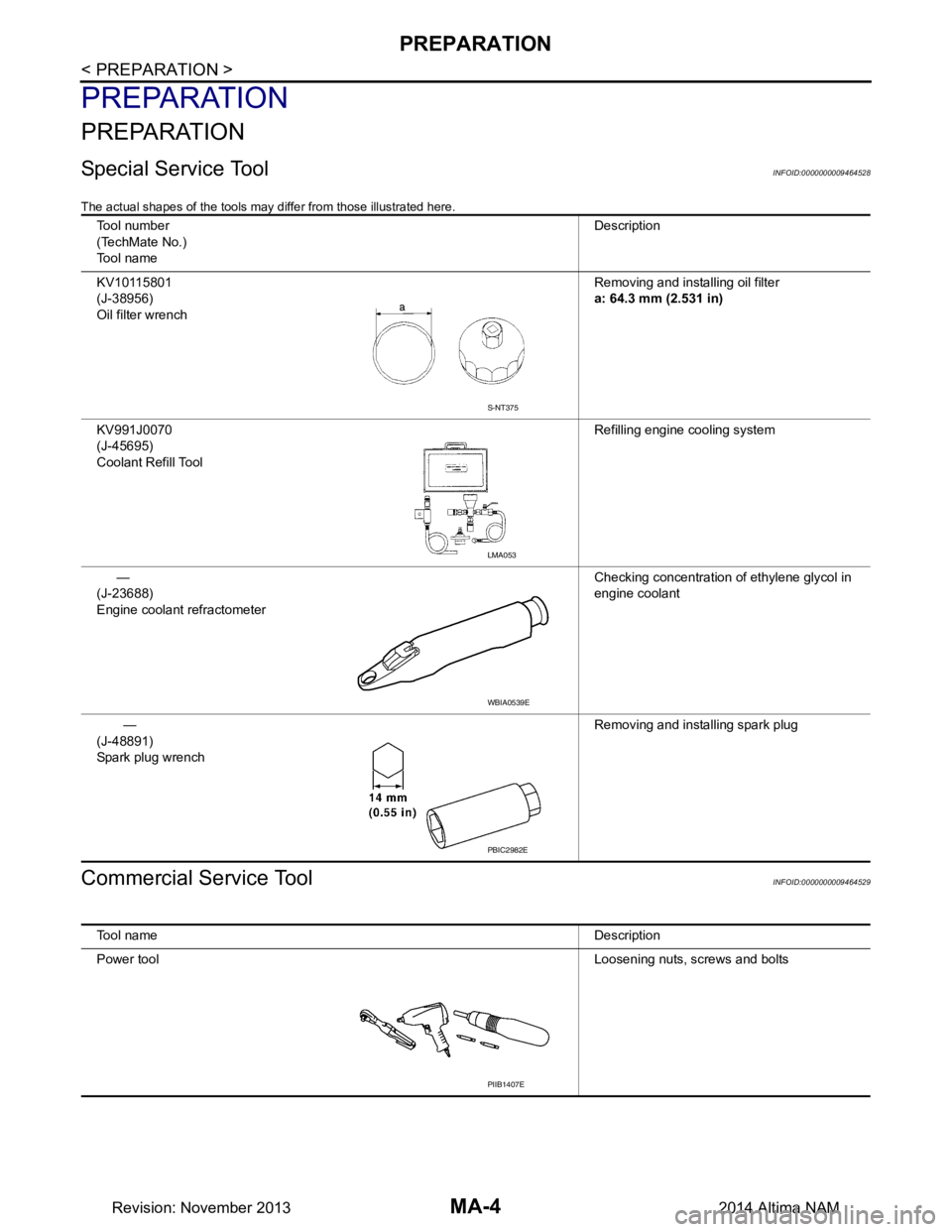
Special Service ToolINFOID:0000000009464528
The actual shapes of the tools may differ from those illustrated here.
Commercial Service ToolINFOID:0000000009464529
Tool number
(TechMate No.)
Tool name Description
KV10115801
(J-38956)
Oil filter wrench Removing and installing oil filter
a: 64.3 mm (2.531 in)
KV991J0070
(J-45695)
Coolant Refill Tool Refilling engine cooling system
—
(J-23688)
Engine coolant refractometer Checking concentration of ethylene glycol in
engine coolant
—
(J-48891)
Spark plug wrench Removing and installing spark plug
S-NT375
LMA053
WBIA0539E
PBIC2982E
Tool name
Description
Power tool Loosening nuts, screws and bolts
PIIB1407E
Revision: November 20132014 Altima NAM
Page 3201 of 4801
ENGINE MAINTENANCE (QR25DE)MA-17
< PERIODIC MAINTENANCE >
C
D E
F
G H
I
J
K L
M B
MA
N
O A
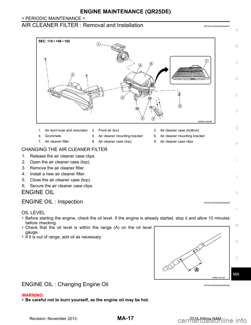
AIR CLEANER FILTER : Removal and InstallationINFOID:0000000009464547
CHANGING THE AIR CLEANER FILTER
1. Release the air cleaner case clips.
2. Open the air cleaner case (top).
3. Remove the air cleaner filter.
4. Install a new air cleaner filter.
5. Close the air cleaner case (top).
6. Secure the air cleaner case clips.
ENGINE OIL
ENGINE OIL : InspectionINFOID:0000000009464548
OIL LEVEL
• Before starting the engine, check the oil level. If t he engine is already started, stop it and allow 10 minutes
before checking.
• Check that the oil level is within the range (A) on the oil level gauge.
• If it is out of range, add oil as necessary.
ENGINE OIL : Changing Engine OilINFOID:0000000009464549
WARNING:
• Be careful not to burn yourself, as the engine oil may be hot.
1. Air duct hose and resonator 2. Front air duct 3. Air cleaner case (bottom)
4. Grommets 5. Air cleaner mounting bracket 6. Air cleaner mounting bracket
7. Air cleaner filter 8. Air cleaner case (top) 9. Air cleaner case clips
AWBIA1294GB
JPBIA1497ZZ
Revision: November 20132014 Altima NAM
Page 3211 of 4801
ENGINE MAINTENANCE (VQ35DE)MA-27
< PERIODIC MAINTENANCE >
C
D E
F
G H
I
J
K L
M B
MA
N
O A
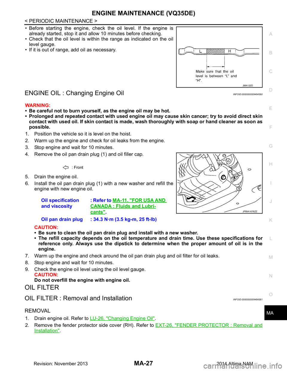
• Before starting the engine, check the oil level. If the engine is
already started, stop it and a llow 10 minutes before checking.
• Check that the oil level is within the range as indicated on the oil
level gauge.
• If it is out of range, add oil as necessary.
ENGINE OIL : Changing Engine OilINFOID:0000000009464560
WARNING:
• Be careful not to burn yourself, as the engine oil may be hot.
• Prolonged and repeated contact with used engine oil may cau se skin cancer; try to avoid direct skin
contact with used oil. If skin contact is made, w ash thoroughly with soap or hand cleaner as soon as
possible.
1. Position the vehicle so it is level on the hoist.
2. Warm up the engine and check for oil leaks from the engine.
3. Stop engine and wait for 10 minutes.
4. Remove the oil pan drain plug (1) and oil filler cap.
5. Drain the engine oil.
6. Install the oil pan drain plug (1) with a new washer and refill the engine with new engine oil.
CAUTION:
• Be sure to clean the oil pan drain plug and install with a new washer.
• The refill capacity depends on the oil temper ature and drain time. Use these specifications for
reference only. Always use the dipstick to determin e when the proper amount of oil is in the
engine.
7. Warm up the engine and check around the oil pan drain plug and oil filter for oil leaks.
8. Stop engine and wait for 10 minutes.
9. Check the engine oil level using the oil level gauge. CAUTION:
Do not overfill the en gine with engine oil.
OIL FILTER
OIL FILTER : Removal and InstallationINFOID:0000000009464561
REMOVAL
1. Drain engine oil. Refer to LU-26, "Changing Engine Oil".
2. Remove the fender protector side cover (RH). Refer to EXT-26, "FENDER PROTECTOR : Removal and
Installation".
JMA122D
: Front
Oil specification
and viscosity : Refer to
MA-11, "FOR USA AND
CANADA : Fluids and Lubri-
cants".
Oil pan drain plug : 34.3 N·m (3.5 kg-m, 25 ft-lb)JPBIA1676ZZ
Revision: November 20132014 Altima NAM
Page 3722 of 4801
REAR SUSPENSION ASSEMBLYRSU-5
< PERIODIC MAINTENANCE >
C
D
F
G H
I
J
K L
M A
B
RSU
N
O P
PERIODIC MAINTENANCE
REAR SUSPENSION ASSEMBLY
On-vehicle ServiceINFOID:0000000009464454
• Check the suspension parts for excessive play, cracks, wear or damage. Shake each rear wheel to check for
excessive play.
• Retighten all nuts and bolts to the specified torque.
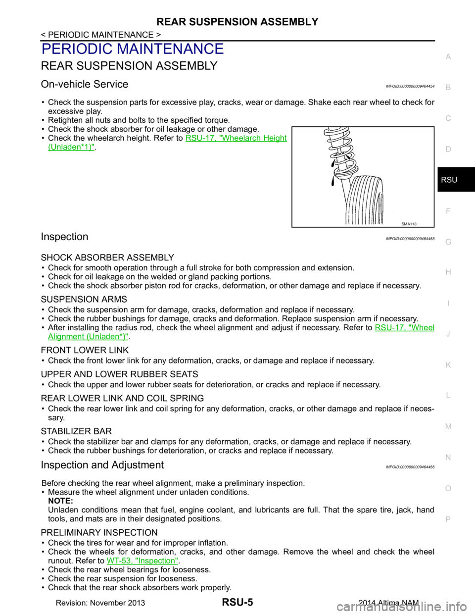
• Check the shock absorber for oil leakage or other damage.
• Check the wheelarch height. Refer to RSU-17, "Wheelarch Height
(Unladen*1)".
InspectionINFOID:0000000009464455
SHOCK ABSORBER ASSEMBLY
• Check for smooth operation through a full stroke for both compression and extension.
• Check for oil leakage on the welded or gland packing portions.
• Check the shock absorber piston r od for cracks, deformation, or other damage and replace if necessary.
SUSPENSION ARMS
• Check the suspension arm for damage, cracks, deformation and replace if necessary.
• Check the rubber bushings for damage, cracks and defo rmation. Replace suspension arm if necessary.
• After installing the radius rod, check the wheel alignment and adjust if necessary. Refer to RSU-17, "Wheel
Alignment (Unladen*)".
FRONT LOWER LINK
• Check the front lower link for any deformation, cracks, or damage and replace if necessary.
UPPER AND LOWER RUBBER SEATS
• Check the upper and lower rubber seats for deterioration, or cracks and replace if necessary.
REAR LOWER LINK AND COIL SPRING
• Check the rear lower link and coil spring for any def ormation, cracks, or other damage and replace if neces-
sary.
STABILIZER BAR
• Check the stabilizer bar and clamps for any deformation, cracks, or damage and replace if necessary.
• Check the rubber bushings for deterioration, or cracks and replace if necessary.
Inspection and AdjustmentINFOID:0000000009464456
Before checking the rear wheel ali gnment, make a preliminary inspection.
• Measure the wheel alignment under unladen conditions. NOTE:
Unladen conditions mean that fuel, engine coolant, and l ubricants are full. That the spare tire, jack, hand
tools, and mats are in their designated positions.
PRELIMINARY INSPECTION
• Check the tires for wear and for improper inflation.
• Check the wheels for deformation, cracks, and ot her damage. Remove the wheel and check the wheel
runout. Refer to WT-53, "Inspection"
.
• Check the rear wheel bearings for looseness.
• Check the rear suspension for looseness.
• Check that the rear shock absorbers work properly.
SMA113
Revision: November 20132014 Altima NAM
Page 4133 of 4801
ST-30
< PERIODIC MAINTENANCE >
POWER STEERING FLUID
PERIODIC MAINTENANCE
POWER STEERING FLUID
Draining and RefillingINFOID:0000000009461266
DRAINING
1. Disconnect the high and low pressure piping from power steering gear.
2. Drain power steering fluid into a suitable container.
REFILLING
1. Fill power steering reservoir while checking power steering fluid level.
2. Bleed air from power steering hydraulic system. Refer to ST-30, "Air Bleeding Hydraulic System"
.
3. Check for power steering fluid leaks.
Air Bleeding Hydraulic SystemINFOID:0000000009461267
AIR BLEEDING HYDRAULIC SYSTEM
If air bleeding is not complete, excessive noise in the power steering oil pump will be present.
1. Make sure engine is off.
2. Turn the steering wheel from the full right stop pos ition and then to full left stop position several times.
Repeat until bubbles are no longer being generated in the reservoir.
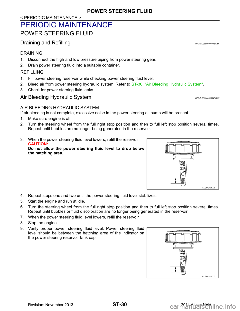
3. When the power steering fluid level lowers, refill the reservoir. CAUTION:
Do not allow the power steerin g fluid level to drop below
the hatching area.
4. Repeat steps one and two until the power steering fluid level stabilizes.
5. Start the engine and run at idle.
6. Turn the steering wheel from the full right stop pos ition and then to full left stop position several times.
Repeat until bubbles or fluid discoloration are no longer being generated in the reservoir.
7. When the power steering fluid level lowers, refill the reservoir.
8. Stop the engine.
9. Verify proper power steering fluid level. Power steering fluid level should be between the hatching area of the indicator on
the power steering reservoir tank cap.
ALGIA0125ZZ
ALGIA0125ZZ
Revision: November 20132014 Altima NAMRevision: November 20132014 Altima NAM
Page 4235 of 4801
![NISSAN TEANA 2014 Service Manual
TM-20
< SYSTEM DESCRIPTION >[CVT: RE0F10D]
COMPONENT PARTS
• The principle of the linear solenoid valve utilizes the fa
ct that the force pressing on the valve spool installed
inside the coil incre NISSAN TEANA 2014 Service Manual
TM-20
< SYSTEM DESCRIPTION >[CVT: RE0F10D]
COMPONENT PARTS
• The principle of the linear solenoid valve utilizes the fa
ct that the force pressing on the valve spool installed
inside the coil incre](/manual-img/5/57390/w960_57390-4234.png)
TM-20
< SYSTEM DESCRIPTION >[CVT: RE0F10D]
COMPONENT PARTS
• The principle of the linear solenoid valve utilizes the fa
ct that the force pressing on the valve spool installed
inside the coil increases nearly in proportion to the current . This allows it to produce a fluid pressure that is
proportional to this pressing force.
• The N/L (normal low) type does not produce hydr aulic control when the coil is not energized.
CVT CONTROL SYSTEM : Line Pressure Solenoid ValveINFOID:0000000009463975
• The line pressure solenoid valve is installed to control valve.
• The line pressure solenoid valve controls the pressure regulator valve. For information about the pressure
regulator valve, refer to TM-27, "TRANSAXLE : Component Description"
.
• The line pressure solenoid valve uses the linear solenoid valve [N/H (normal high) type]. NOTE:
• The principle of the linear solenoid valve utilizes the fa ct that the force pressing on the valve spool installed
inside the coil increases nearly in proportion to the current . This allows it to produce a fluid pressure that is
proportional to this pressing force.
• The N/H (normal high) produces hydraulic control when the coil is not energized.
CVT CONTROL SYSTEM : Overdrive Control SwitchINFOID:0000000009463976
• The overdrive control switch is inst alled to the selector lever knob.
• If the overdrive control switch is pressed when the O/D OFF indicator lamp on the combination meter is not
lit, the status changes to overdrive OFF and the O/D OFF indicator lamp illuminates.
• If the overdrive control switch is pressed when the O/ D OFF indicator lamp on the combination meter is lit,
the overdrive OFF status is canceled and the O/D OFF indicator lamp turns off.
CVT CONTROL SYSTEM : O/D OFF Indicator LampINFOID:0000000009463977
• O/D OFF indicator lamp is positioned on the combination meter.
• The O/D OFF indicator lamp illuminates when the overdrive function is deactivated (O/D OFF).
• For checking the bulb, this lamp turns on for a cert ain period of time when the ignition switch turns ON,
andthen turns off.
CVT CONTROL SYSTEM : Sh ift Position IndicatorINFOID:0000000009463978
TCM transmits shift position signal to combination meter via CAN communication. The actual shift position is
displayed on combination meter according to the signal.
SHIFT LOCK SYSTEM
Condition (status) O/D OFF indicator lamp
Ignition switch OFF. OFF
Ignition switch ON. ON (Approx. 2 seconds)
Overdrive control switch is pressed when the selector lever is in
the D position and the O/D OFF indicator lamp is OFF (when sys-
tem is normal). ON
Overdrive control switch is pressed when the selector lever is in
the D position and the O/D OFF indicator lamp is ON. OFF
Selector lever is shifted from the D position to another position-
when the O/D OFF indicator lamp is ON. OFF
Revision: November 20132014 Altima NAMRevision: November 20132014 Altima NAM