2014 NISSAN TEANA steering
[x] Cancel search: steeringPage 4156 of 4801

COMPONENT PARTSSTC-5
< SYSTEM DESCRIPTION >
C
D E
F
H I
J
K L
M A
B
STC
N
O P
Power Steering Oil Pump AssemblyINFOID:0000000009460343
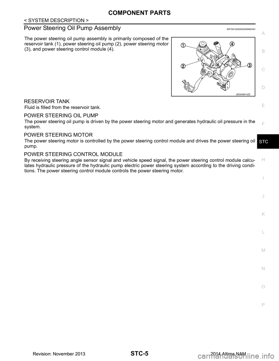
The power steering oil pump assembly is primarily composed of the
reservoir tank (1), power steering oil pump (2), power steering motor
(3), and power steering control module (4).
RESERVOIR TANK
Fluid is filled from the reservoir tank.
POWER STEERING OIL PUMP
The power steering oil pump is driven by the power steer ing motor and generates hydraulic oil pressure in the
system.
POWER STEERING MOTOR
The power steering motor is controll ed by the power steering control module and drives the power steering oil
pump.
POWER STEERING CONTROL MODULE
By receiving steering angle sensor signal and vehicle speed signal, the power steering control module calcu-
lates hydraulic pressure of the hydraulic pump electric power steering system according to the driving condi-
tions. The power steering control modul e controls the power steering motor.
JSGIA0914ZZ
Revision: November 20132014 Altima NAMRevision: November 20132014 Altima NAM
Page 4157 of 4801

STC-6
< SYSTEM DESCRIPTION >
SYSTEM
SYSTEM
HYDRAULIC PUMP ELECTRIC POWER STEERING SYSTEM
HYDRAULIC PUMP ELECTRIC POWER ST EERING SYSTEM : System Description
INFOID:0000000009460344
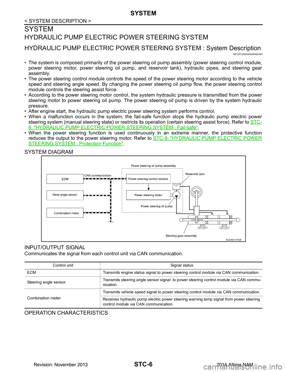
• The system is composed primarily of the power steeri ng oil pump assembly (power steering control module,
power steering motor, power steering oil pump, and reservoir tank), hydraulic pipes, and steering gear
assembly.
• The power steering control module controls the speed of the power steering motor according to the vehicle
speed and steering angle speed. By changing the power st eering oil pump flow, the power steering control
module controls the steering assist force.
• According to the power steering motor control, the sy stem hydraulic pressure is transmitted from the power
steering motor to power steering oil pump. The power steering oil pump is driven by the system hydraulic
pressure.
• After engine start, the hydraulic pump electric power steering system performs control.
• When a malfunction occurs in the system, the fail-safe function stops the hydraulic pump electric power
steering system (manual steering state) or restricts it s operation (certain steering assist force). Refer to STC-
8, "HYDRAULIC PUMP ELECTRIC POWER STEERING SYSTEM : Fail-safe".
• When the power steering function is used continuously in an extreme manner, the protective function
reduces the output to the power steering motor. Refer to STC-9, "HYDRAULIC PUMP ELECTRIC POWER
STEERING SYSTEM : Protection Function".
SYSTEM DIAGRAM
INPUT/OUTPUT SIGNAL
Communicates the signal from each control unit via CAN communication.
OPERATION CHARACTERISTICS
ALGIA0127GB
Control unit Signal status
ECM Transmits engine status signal to power steering control module via CAN communication.
Steering angle sensor Transmits steering angle sensor signal to power steering control module via CAN commu-
nication.
Combination meter Transmits vehicle speed signal to power steering control module via CAN communication.
Receives hydraulic pump electric power steering warning lamp signal from power steering
control module via CAN communication.
Revision: November 20132014 Altima NAMRevision: November 20132014 Altima NAM
Page 4158 of 4801

SYSTEMSTC-7
< SYSTEM DESCRIPTION >
C
D E
F
H I
J
K L
M A
B
STC
N
O P
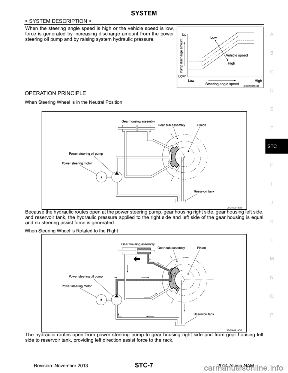
When the steering angle speed is high or the vehicle speed is low,
force is generated by increasing discharge amount from the power
steering oil pump and by raising system hydraulic pressure.
OPERATION PRINCIPLE
When Steering Wheel is in the Neutral Position
Because the hydraulic routes open at the power steeri ng pump, gear housing right side, gear housing left side,
and reservoir tank, the hydraulic pressure applied to the right side and left side of the gear housing is equal
and no steering assist force is generated.
When Steering Wheel is Rotated to the Right
The hydraulic routes open from power steering pump to gear housing right side and from gear housing left
side to reservoir tank, providing left direction assist force to the rack.
JSGIA0916GB
JSGIA0918GB
JSGIA0919GB
Revision: November 20132014 Altima NAMRevision: November 20132014 Altima NAM
Page 4159 of 4801

STC-8
< SYSTEM DESCRIPTION >
SYSTEM
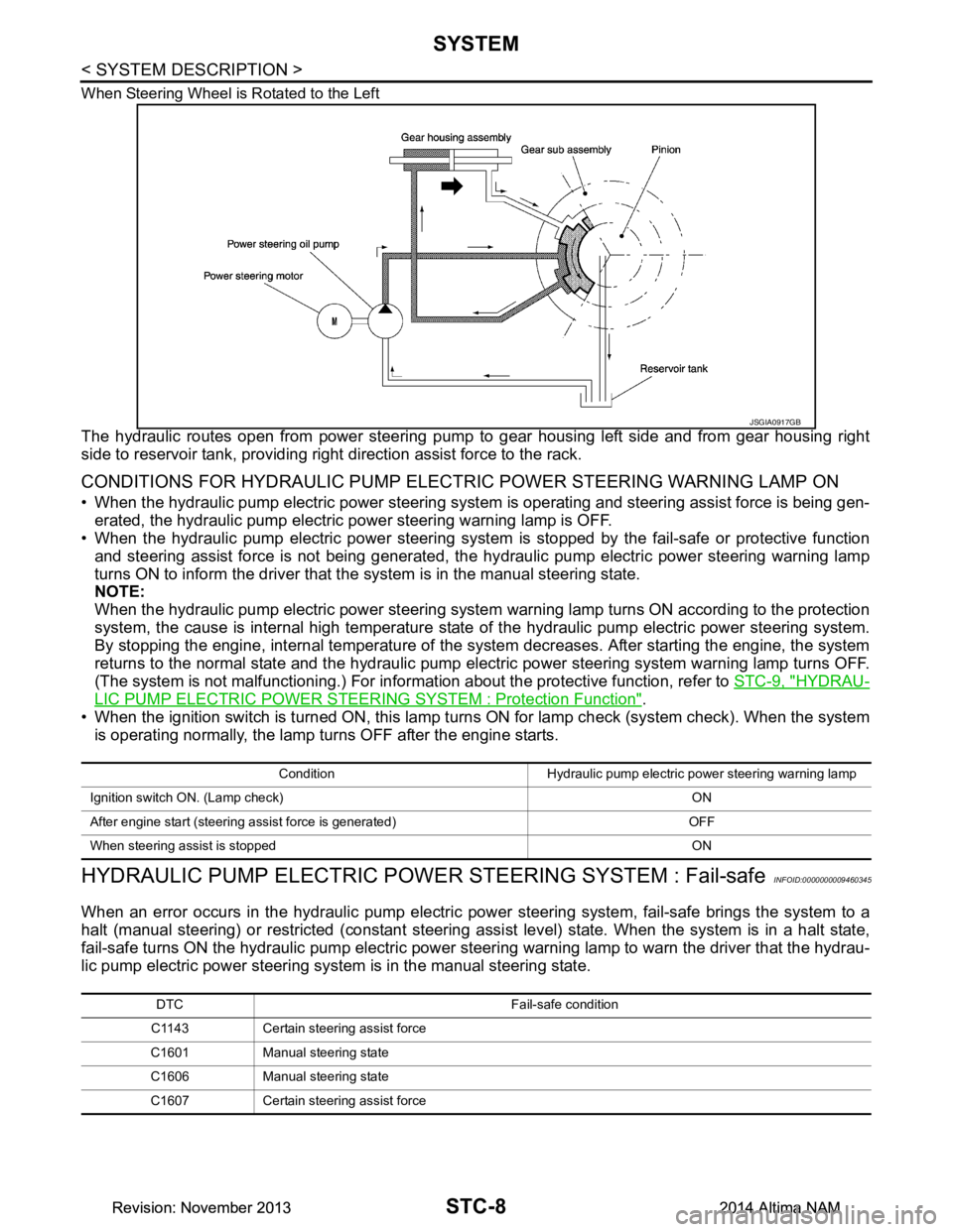
When Steering Wheel is Rotated to the Left
The hydraulic routes open from power steering pump to gear housing left side and from gear housing right
side to reservoir tank, providing right direction assist force to the rack.
CONDITIONS FOR HYDRAULIC PUMP ELECTR IC POWER STEERING WARNING LAMP ON
• When the hydraulic pump electric power steering syst em is operating and steering assist force is being gen-
erated, the hydraulic pump electric power steering warning lamp is OFF.
• When the hydraulic pump electric power steering system is stopped by the fail-safe or protective function
and steering assist force is not being generated, the hy draulic pump electric power steering warning lamp
turns ON to inform the driver that t he system is in the manual steering state.
NOTE:
When the hydraulic pump electric power steering system warning lamp turns ON according to the protection
system, the cause is internal high temperature state of the hydraulic pump electric power steering system.
By stopping the engine, internal temperature of the s ystem decreases. After starting the engine, the system
returns to the normal state and the hydraulic pump elec tric power steering system warning lamp turns OFF.
(The system is not malfunctioning.) For informat ion about the protective function, refer to STC-9, "HYDRAU-
LIC PUMP ELECTRIC POWER STEERING SYSTEM : Protection Function".
• When the ignition switch is turned ON, this lamp turn s ON for lamp check (system check). When the system
is operating normally, the lamp turns OFF after the engine starts.
HYDRAULIC PUMP ELECTRIC POWE R STEERING SYSTEM : Fail-safeINFOID:0000000009460345
When an error occurs in the hydraulic pump electric pow er steering system, fail-safe brings the system to a
halt (manual steering) or restricted (constant steering assi st level) state. When the system is in a halt state,
fail-safe turns ON the hydraulic pump electric power steer ing warning lamp to warn the driver that the hydrau-
lic pump electric power steering system is in the manual steering state.
JSGIA0917GB
Condition Hydraulic pump electric power steering warning lamp
Ignition switch ON. (Lamp check) ON
After engine start (steering assist force is generated) OFF
When steering assist is stopped ON
DTC Fail-safe condition
C1143 Certain steering assist force
C1601 Manual steering state
C1606 Manual steering state
C1607 Certain steering assist force
Revision: November 20132014 Altima NAMRevision: November 20132014 Altima NAM
Page 4160 of 4801

SYSTEMSTC-9
< SYSTEM DESCRIPTION >
C
D E
F
H I
J
K L
M A
B
STC
N
O P
HYDRAULIC PUMP ELECTRIC POWER STEE RING SYSTEM : Protection Function
INFOID:0000000009460346
• When the steering wheel is operated repeatedly or turned all the way for a long period during parking or low
speed driving, the function of the hydraulic pump elec tric power steering system becomes limited to prevent
the system from overheating. Cont inued operation of the steering wheel will cause the hydraulic pump elec-
tric power steering system to stop and the hydraulic pum p electric power steering system warning lamp may
come ON. In this case, the steering wheel operation temporarily becomes hard. This is not a malfunction.
When the engine is turned OFF (ignition switch OFF) and steering operation is stopped for a while, the tem-
perature of the hydraulic pump electric power steer ing system decreases and the steering operation returns
to normal after restarting the engine.
• Then, the hydraulic pump electric power steering syste m warning lamp turns OFF. If the system is OFF
under the protection state, the hydraulic pump electr ic power steering system warning lamp turns ON to
warn that the system is in the manual steering state. (This is not a system malfunction.) In addition, the fol-
lowing DTC remains to distinguish from malfunction.
C1608 Manual steering state
U1000 Normal control
NOTE:
If the cause is in a different ECU, the state changes to fixed steering assist force.
DTC Fail-safe condition
DTC vehicle condition
C160A The system temporarily enters the manual steering state. (This is not a hydraulic pump electric
power steering system malfunction.)
Revision: November 20132014 Altima NAMRevision: November 20132014 Altima NAM
Page 4161 of 4801

STC-10
< SYSTEM DESCRIPTION >
DIAGNOSIS SYSTEM (POWER STEERING CONTROL MODULE)
DIAGNOSIS SYSTEM (POWER STEERING CONTROL MODULE)
CONSULT FunctionINFOID:0000000009460347
CAUTION:
After disconnecting the CONSULT vehicle interface (VI) from the data link connector, the ignition must
be cycled OFF → ON (for at least 5 seconds) → OFF. If this step is not performed, the BCM may not go
to ”sleep mode”, potentially causing a di scharged battery and a no-start condition.
FUNCTION
CONSULT can display each diagnostic item using the diagnostic test modes shown as per the following.
ECU IDENTIFICATION
Displays the part number stored in the control unit.
SELF-DIAG RESULTS MODE
Refer to STC-13, "DTC Index".
When “CRNT” is displayed on self-diagnosis result.
• The system is presently malfunctioning.
When “PAST” is displayed on self-diagnosis result.• System malfunction in the past is detect ed, but the system is presently normal.
DATA MONITOR MODE
Diagnostic test mode Function
ECU identification The part number stored in the control unit can be read.
Self Diagnostic Results Self-diagnostic results and freeze frame data can be read and erased quickly.
Data monitor Input/Output data in the power steering control module can be read.
Monitor item (Unit) Remarks
BATTERY VOLT (V) Displays the power supply voltage for power steering control module.
STEERING ANGLE (deg) Displays the steering angle based on the steering angle signal transmitted by CAN com-
munications.
STR ANG SPD (deg/s) Displays the steering angle speed based on the steering angle signal transmitted by
CAN communications.
MOTOR CURRENT (A) Displays the cu rrent value consumed by power steering control module.
MTR REV SPD COMM (rpm) Displa ys the power steering motor speed command value.
MTR REV SPD (rpm) Displays the power steering motor speed.
C/U TEMP ( °C or °F) Displays the temperature of the power steering control module.
C/U TEMP A ( °C or °F) Displays the temperature of the power steering control module.
MTR ASSIST (%) Displays the current percentage of the allowable assist ratio power steering motor.
ESTM VHCL SPD (km/h or mph) Displays the vehicle speed calculated by the power steering control module.
WARNING LAMP (On/Off) Hydraulic pump electric power steering system warning lamp control status is displayed.
ENGINE STATUS (STOP/RUN/CRANK) Engine speed is displayed from engine condition signal with CAN communication
VHCL SPD JUDGE (OK/NG) Displays the receiving status of the vehicle speed signal transmitted by CAN communi-
cations.
Revision: November 20132014 Altima NAMRevision: November 20132014 Altima NAM
Page 4162 of 4801

POWER STEERING CONTROL MODULESTC-11
< ECU DIAGNOSIS INFORMATION >
C
D E
F
H I
J
K L
M A
B
STC
N
O P
ECU DIAGNOSIS INFORMATION
POWER STEERING CONTROL MODULE
Reference ValueINFOID:0000000009460348
VALUES ON THE DIAGNOSIS TOOL
*1: The value changes according to load of power steering motor.
*2: This is in close agreement with a motor speed command value. Although a quick steering operation may
cause disagreement, this is not a malfunction.
*3: Usually, 100% is displayed. An excessive steer ing operation gradually lowers the percentage. When left
standing, the percentage returns to 100%.
Monitor item Data monitor
Condition Display value
BATTERY VOLT Engine running Battery voltage (V)
STEERING ANGLE The steering wheel is not steered. Approx. 0.0 deg
The steering wheel is steered. Displays steering angle (deg)
STR ANG SPD The steering wheel is not steered. Approx. 0.0 deg/s
The steering wheel is steered. Displays steering angle speed (deg/s)
MOTOR CURRENT Engine running Steering wheel: Not steering (There is
no steering force) MAX approx. 10 A
*1
Steering wheel: Right or left turnDisplays consumption current of pow-
er steering control module (A)
MTR REV SPD COMM Engine running Steering wheel: Not steering (There is
no steering force) Shows an almost constant value
(rpm)
Steering wheel: Right or left turn The value changes as a steering
speed (rpm)
MTR REV SPD Engine running Steering wheel: Not steering (There is
no steering force) Shows an almost constant value
(rpm)
*2
Steering wheel: Right or left turn The value changes as a steering
speed (rpm)*2
C/U TEMP Engine running Displays temperature of inside of
power steering control module ( °C or
° F)
C/U TEMP A Engine running Displays temperature of inside of
power steering control module ( °C or
° F)
MTR ASSIST Engine running 100%
*3
ESTM VHCL SPDVehicle stopped 0.00 km/h or mph
While driving Approximately equal to the indication
on speedometer*4
(inside of ±10%)
WARNING LAMP Hydraulic pump electric power steering warning lamp: ON On
Hydraulic pump electric power steering warning lamp: OFF Off
ENGINE STATUS Engine not running STOP
Engine running RUN
Engine cranking CRANK
VHCL SPD JUDGE Vehicle speed signal can be received via CAN communication OK
Vehicle speed signal cannot be received via CAN communica-
tion NG
Revision: November 20132014 Altima NAMRevision: November 20132014 Altima NAM
Page 4163 of 4801

STC-12
< ECU DIAGNOSIS INFORMATION >
POWER STEERING CONTROL MODULE
*4: This may not agree with the speedometer indication immediately after the ignition switch is turned ON. This
is not a malfunction.
TERMINAL LAYOUT
PHYSICAL VALUES
Fail-safeINFOID:0000000009460349
When an error occurs in the hydraulic pump electric pow er steering system, fail-safe brings the system to a
halt (manual steering) or restricted (constant steering assi st level) state. When the system is in a halt state,
fail-safe turns ON the hydraulic pump electric power steer ing warning lamp to warn the driver that the hydrau-
lic pump electric power steering system is in the manual steering state.
Protection FunctionINFOID:0000000009460350
• When the steering wheel is operated repeatedly or turned all the way for a long period during parking or low
speed driving, the function of the hydraulic pump elec tric power steering system becomes limited to prevent
the system from overheating. If the steering wheel is operated further more, the hydraulic pump electric
power steering system stops and the hydraulic pump el ectric power steering system warning lamp may be
turned ON. In this case, the steering wheel operation temporarily becomes hard. This is not a malfunction.
When the engine is turned OFF (ignition switch OFF) and steering operation is stopped for a while, the tem-
perature of the hydraulic pump electric power steeri ng system decreases and the steering operation returns
to normal after restarting the engine.
JSGIA0835ZZ
Te r m i n a l N o .
(Wire Color) Description
Condition Value
+ − Signal name Input/Output
1
(W) Ground Battery power supply Input Always Battery Voltage
2
(B) Ground Ground — Always 0 V
5
(BR) Ground Ignition power supply Input Ignition switch: ON Battery Voltage
Ignition switch: OFF 0 V
7
(P) — CAN-L Input/Output — —
8
(L) — CAN-H Input/Output — —
DTC Fail-safe condition
C1143 Certain steering assist force
C1601 Manual steering state
C1606 Manual steering state
C1607 Certain steering assist force
C1608 Manual steering state
U1000 Normal control
NOTE:
If the cause is in a different ECU, the state changes to fixed steering assist force.
Revision: November 20132014 Altima NAMRevision: November 20132014 Altima NAM