2014 NISSAN TEANA steering
[x] Cancel search: steeringPage 4189 of 4801

STC-38
< SYMPTOM DIAGNOSIS >
UNBALANCE STEERING WHEEL TURNING FORCE (TORQUE VARIATION)
NO >> Check the combination meter, ABS actuator and electric unit (control unit). Refer to MWI-18,
"CONSULT Function (METER/M&A)" and BRC-33, "CONSULT Function (ABS)".
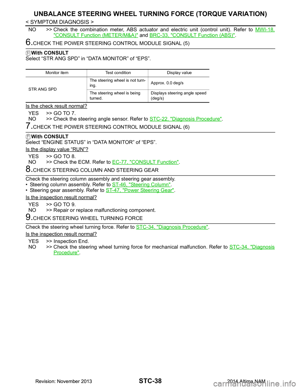
6.CHECK THE POWER STEERING CONTROL MODULE SIGNAL (5)
With CONSULT
Select “STR ANG SPD” in “DATA MONITOR” of “EPS”.
Is the check result normal?
YES >> GO TO 7.
NO >> Check the steering angle sensor. Refer to STC-22, "Diagnosis Procedure"
.
7.CHECK THE POWER STEERING CONTROL MODULE SIGNAL (6)
With CONSULT
Select “ENGINE STATUS” in “DATA MONITOR” of “EPS”.
Is the display value
“RUN”?
YES >> GO TO 8.
NO >> Check the ECM. Refer to EC-77, "CONSULT Function"
.
8.CHECK STEERING COLUMN AND STEERING GEAR
Check the steering column assembly and steering gear assembly.
• Steering column assembly. Refer to ST-46, "Steering Column"
.
• Steering gear assembly. Refer to ST-47, "Power Steering Gear"
.
Is the inspection result normal?
YES >> GO TO 9.
NO >> Repair or replace malfunctioning component.
9.CHECK STEERING WHEEL TURNING FORCE
Check the steering wheel turning force. Refer to STC-34, "Diagnosis Procedure"
.
Is the inspection result normal?
YES >> Inspection End.
NO >> Check the steering wheel turning force for mechanical malfunction. Refer to STC-34, "Diagnosis
Procedure".
Monitor item Test condition Display value
STR ANG SPD The steering wheel is not turn-
ing. Approx. 0.0 deg/s
The steering wheel is being
turned. Displays steering angle speed
(deg/s)
Revision: November 20132014 Altima NAMRevision: November 20132014 Altima NAM
Page 4190 of 4801

POWER STEERING CONTROL MODULESTC-39
< UNIT REMOVAL AND INSTALLATION >
C
D E
F
H I
J
K L
M A
B
STC
N
O P
UNIT REMOVAL AND INSTALLATION
POWER STEERING CONTROL MODULE
Removal and InstallationINFOID:0000000009460379
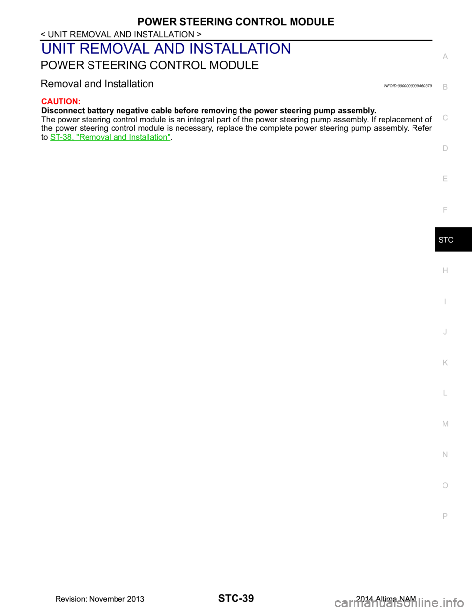
CAUTION:
Disconnect battery negative cable before removing the power steering pump assembly.
The power steering control module is an integral part of the power steering pump assembly. If replacement of
the power steering control module is necessary, replac e the complete power steering pump assembly. Refer
to ST-38, "Removal and Installation"
.
Revision: November 20132014 Altima NAMRevision: November 20132014 Altima NAM
Page 4438 of 4801
![NISSAN TEANA 2014 Service Manual
COMPONENT PARTSTM-223
< SYSTEM DESCRIPTION > [CVT: RE0F10E]
C
EF
G H
I
J
K L
M A
B
TM
N
O P
NOTE:
• The principle of the linear solenoid valve utilizes the fa ct that the force pressing on the va NISSAN TEANA 2014 Service Manual
COMPONENT PARTSTM-223
< SYSTEM DESCRIPTION > [CVT: RE0F10E]
C
EF
G H
I
J
K L
M A
B
TM
N
O P
NOTE:
• The principle of the linear solenoid valve utilizes the fa ct that the force pressing on the va](/manual-img/5/57390/w960_57390-4437.png)
COMPONENT PARTSTM-223
< SYSTEM DESCRIPTION > [CVT: RE0F10E]
C
EF
G H
I
J
K L
M A
B
TM
N
O P
NOTE:
• The principle of the linear solenoid valve utilizes the fa ct that the force pressing on the valve spool installed
inside the coil increases nearly in proportion to the current . This allows it to produce a fluid pressure that is
proportional to this pressing force.
• The N/H (normal high) produces hydraulic control when the coil is not energized.
CVT CONTROL SYSTEM : Se lect Solenoid ValveINFOID:0000000009464191
• The select solenoid valve is installed to control valve.
• The select solenoid valve adjusts the tightening pressure of the forward clutch and reverse brake. For infor-
mation about the forward clutch and reverse brake, refer to TM-229, "TRANSAXLE : Component Descrip-
tion".
• The select solenoid valve uses the linear solenoid valve [N/H (normal high) type]. NOTE:
• The principle of the linear solenoid valve utilizes the fa ct that the force pressing on the valve spool installed
inside the coil increases nearly in proportion to the current . This allows it to produce a fluid pressure that is
proportional to this pressing force.
• The N/H (normal high) type produces hydraulic control when the coil is not energized.
CVT CONTROL SYSTEM : Torque Converter Clutch Solenoid ValveINFOID:0000000009464192
• The torque converter clutch solenoid valve is installed to control valve.
• The torque converter clutch solenoid valve controls the torque converter clutch control valve. For information
about the torque converter clutch control valve, refer to TM-229, "TRANSAXLE : Component Description"
.
• The torque converter clutch solenoid valve utilizes a linear solenoid valve [N/L (normal low) type]. NOTE:
• The principle of the linear solenoid valve utilizes the fa ct that the force pressing on the valve spool installed
inside the coil increases nearly in proportion to the current . This allows it to produce a fluid pressure that is
proportional to this pressing force.
• The N/L (normal low) type does not produce hydraulic control when the coil is not energized.
CVT CONTROL SYSTEM : Line Pressure Solenoid ValveINFOID:0000000009464193
• The line pressure solenoid valve is installed to control valve.
• The line pressure solenoid valve controls the pressu re regulator valve. For information about the pressure
regulator valve, refer to TM-229, "TRANSAXLE : Component Description"
.
• The line pressure solenoid valve uses the linear solenoid valve [N/H (normal high) type]. NOTE:
• The principle of the linear solenoid valve utilizes the fa ct that the force pressing on the valve spool installed
inside the coil increases nearly in proportion to the current . This allows it to produce a fluid pressure that is
proportional to this pressing force.
• The N/H (normal high) produces hydraulic control when the coil is not energized.
CVT CONTROL SYSTEM : Paddle ShifterINFOID:0000000009464194
• The paddle shifter is installed to the steering.
• The paddle shifter transmits shift up and shift down switch signals to the combination meter. Then TCM
receives signals from the combination meter via CAN communication.
PADDLE SHIFTER FUNCTION
CVT CONTROL SYSTEM : Sh ift Position IndicatorINFOID:0000000009464195
TCM transmits shift position signal to combination mete r via CAN communication. The actual shift position is
displayed on combination meter according to the signal.
SHIFT LOCK SYSTEM
Selector lever po-
sition Function
D Although driving in manual mode is possible, selector lever automatically returns to D position after a certain period
of time because the selector lever is not fixed in manual mode.
DS Driving with the selector lever fixed in manual mode is possible.
Revision: November 20132014 Altima NAMRevision: November 20132014 Altima NAM
Page 4597 of 4801
![NISSAN TEANA 2014 Service Manual
TM-382
< REMOVAL AND INSTALLATION >[CVT: RE0F10E]
PADDLE SHIFTER
PADDLE SHIFTER
Exploded ViewINFOID:0000000009464338
Removal and InstallationINFOID:0000000009464339
REMOVAL
1. Park the vehicle on a l NISSAN TEANA 2014 Service Manual
TM-382
< REMOVAL AND INSTALLATION >[CVT: RE0F10E]
PADDLE SHIFTER
PADDLE SHIFTER
Exploded ViewINFOID:0000000009464338
Removal and InstallationINFOID:0000000009464339
REMOVAL
1. Park the vehicle on a l](/manual-img/5/57390/w960_57390-4596.png)
TM-382
< REMOVAL AND INSTALLATION >[CVT: RE0F10E]
PADDLE SHIFTER
PADDLE SHIFTER
Exploded ViewINFOID:0000000009464338
Removal and InstallationINFOID:0000000009464339
REMOVAL
1. Park the vehicle on a level surface.
2. Remove the driver air bag module. Refer to SR-11, "Removal and Installation"
.
3. Remove the steering wheel. Refer to ST-31, "Removal and Installation"
.
4. Remove the column cover. Refer to IP-17, "Removal and Installation"
.
1. Steering column assembly 2. Paddle shifter (shift-down) 3. Paddle shifter (shift-up)
AWDIA0557GB
Revision: November 20132014 Altima NAMRevision: November 20132014 Altima NAM
Page 4598 of 4801
![NISSAN TEANA 2014 Service Manual
PADDLE SHIFTERTM-383
< REMOVAL AND INSTALLATION > [CVT: RE0F10E]
C
EF
G H
I
J
K L
M A
B
TM
N
O P
5. Remove the vehicle harness connector (C) and (D) from paddle shifter.
6. Remove the paddle shifter NISSAN TEANA 2014 Service Manual
PADDLE SHIFTERTM-383
< REMOVAL AND INSTALLATION > [CVT: RE0F10E]
C
EF
G H
I
J
K L
M A
B
TM
N
O P
5. Remove the vehicle harness connector (C) and (D) from paddle shifter.
6. Remove the paddle shifter](/manual-img/5/57390/w960_57390-4597.png)
PADDLE SHIFTERTM-383
< REMOVAL AND INSTALLATION > [CVT: RE0F10E]
C
EF
G H
I
J
K L
M A
B
TM
N
O P
5. Remove the vehicle harness connector (C) and (D) from paddle shifter.
6. Remove the paddle shifter bolts (E) and nuts (F).
7. Remove the paddle shifter from the steering column assembly.
INSTALLATION
Installation is in the reverse order of removal.
(A) : Side of paddle shifter (shift-down)
(B) : Side of paddle shifter (shift-up)
AWDIA0563ZZ
Revision: November 20132014 Altima NAMRevision: November 20132014 Altima NAM
Page 4727 of 4801

WT-52
< SYMPTOM DIAGNOSIS >
NOISE, VIBRATION AND HARSHNESS (NVH) TROUBLESHOOTING
NOISE, VIBRATION AND HARSHNESS (NVH) TROUBLESHOOTING
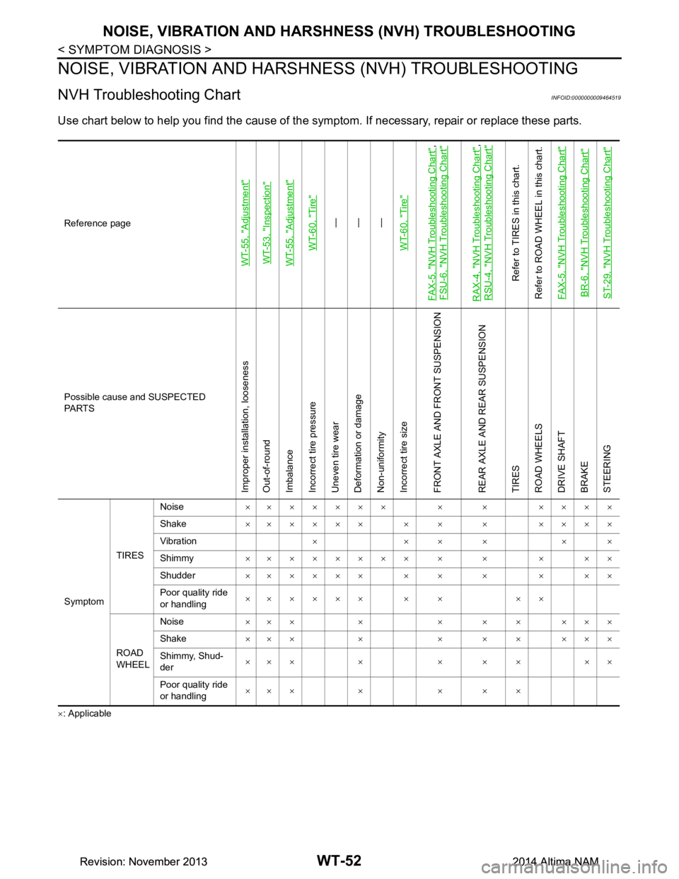
NVH Troubleshooting ChartINFOID:0000000009464519
Use chart below to help you find the cause of the symp tom. If necessary, repair or replace these parts.
×: ApplicableReference page
WT-55, "Adjustment"WT-53, "Inspection"WT-55, "Adjustment"
WT-60, "Tire"
—
—
—
WT-60, "Tire"
FAX-5, "NVH Troubleshooting Chart"
,
FSU-6, "NVH Troubleshooting Chart"
RAX-4, "NVH Troubleshooting Chart"
,
RSU-4, "NVH Troubleshooting Chart"
Refer to TIRES in this chart.
Refer to ROAD WHEEL in this chart.
FAX-5, "NVH Troubleshooting Chart"
BR-6, "NVH Troubleshooting Chart"ST-29, "NVH Troubleshooting Chart"
Possible cause and SUSPECTED
PA R T S
Improper installation, looseness
Out-of-round
Imbalance
Incorrect tire pressure
Uneven tire wear
Deformation or damage
Non-uniformity
Incorrect tire size
FRONT AXLE AND FRONT SUSPENSION
REAR AXLE AND REAR SUSPENSION
TIRES
ROAD WHEELS
DRIVE SHAFT
BRAKE
STEERING
Symptom TIRESNoise
××××××× × × ××××
Shake ×××××× × × × ××××
Vibration ××××××
Shimmy ×××××××× × × × ××
Shudder ×××××× × × × × ××
Poor quality ride
or handling ×××××× × × ××
ROAD
WHEEL Noise
×× × × × × × × × ×
Shake ×× × × × × × × × ×
Shimmy, Shud-
der ×××× ×××××
Poor quality ride
or handling ×× × × × × ×
Revision: November 20132014 Altima NAMRevision: November 20132014 Altima NAM
Page 4734 of 4801

TIRE PRESSURE SENSORWT-59
< UNIT REMOVAL AND INSTALLATION >
C
D
F
G H
I
J
K L
M A
B
WT
N
O P
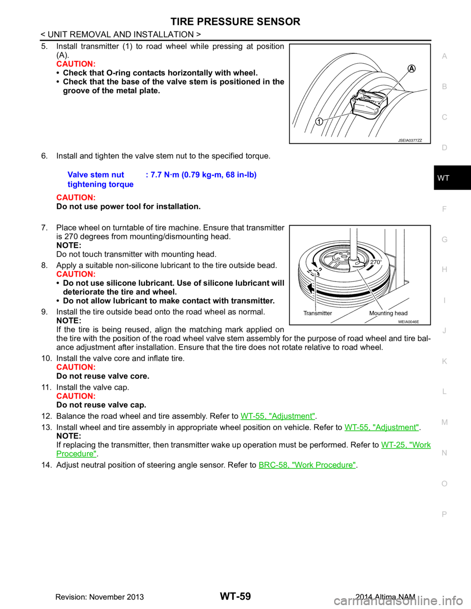
5. Install transmitter (1) to road wheel while pressing at position (A).
CAUTION:
• Check that O-ring contacts horizontally with wheel.
• Check that the base of the valve stem is positioned in the
groove of the metal plate.
6. Install and tighten the valve stem nut to the specified torque. CAUTION:
Do not use power tool for installation.
7. Place wheel on turntable of tire machine. Ensure that transmitter
is 270 degrees from mounting/dismounting head.
NOTE:
Do not touch transmitter with mounting head.
8. Apply a suitable non-silicone lubricant to the tire outside bead. CAUTION:
• Do not use silicone lubricant. Use of silicone lubricant will
deteriorate the tire and wheel.
• Do not allow lubricant to make contact with transmitter.
9. Install the tire outside bead onto the road wheel as normal. NOTE:
If the tire is being reused, align the matching mark applied on
the tire with the position of the road wheel valve st em assembly for the purpose of road wheel and tire bal-
ance adjustment after installation. Ensure that the tire does not rotate relative to road wheel.
10. Install the valve core and inflate tire. CAUTION:
Do not reuse valve core.
11. Install the valve cap. CAUTION:
Do not reuse valve cap.
12. Balance the road wheel and tire assembly. Refer to WT-55, "Adjustment"
.
13. Install wheel and tire assembly in appropriate wheel position on vehicle. Refer to WT-55, "Adjustment"
.
NOTE:
If replacing the transmitter, then transmitter wake up operation must be performed. Refer to WT-25, "Work
Procedure".
14. Adjust neutral position of steering angle sensor. Refer to BRC-58, "Work Procedure"
.
JSEIA0377ZZ
Valve stem nut
tightening torque : 7.7 N·m (0.79 kg-m, 68 in-lb)
WEIA0046E
Revision: November 20132014 Altima NAMRevision: November 20132014 Altima NAM