2014 NISSAN TEANA key
[x] Cancel search: keyPage 4137 of 4801

ST-34
< REMOVAL AND INSTALLATION >
STEERING COLUMN
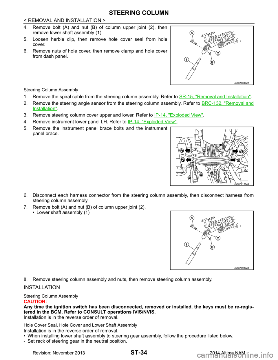
4. Remove bolt (A) and nut (B) of column upper joint (2), thenremove lower shaft assembly (1).
5. Loosen herbie clip, then remove hole cover seal from hole cover.
6. Remove nuts of hole cover, then remove clamp and hole cover from dash panel.
Steering Column Assembly
1. Remove the spiral cable from the steering column assembly. Refer to SR-15, "Removal and Installation".
2. Remove the steering angle sensor from the steering column assembly. Refer to BRC-132, "Removal and
Installation".
3. Remove steering column cover upper and lower. Refer to IP-14, "Exploded View"
.
4. Remove instrument lower panel LH. Refer to IP-14, "Exploded View"
.
5. Remove the instrument panel brace bolts and the instrument panel brace.
6. Disconnect each harness connector from the steeri ng column assembly, then disconnect harness from
steering column assembly.
7. Remove bolt (A) and nut (B) of column upper joint (2). • Lower shaft assembly (1)
8. Remove steering column assembly and nuts, then remove steering column assembly.
INSTALLATION
Steering Column Assembly
CAUTION:
Any time the ignition switch has been disconnected, removed or inst alled, the keys must be re-regis-
tered in the BCM. Refer to CONSULT operations IVIS/NVIS.
Installation is in the reverse order of removal.
Hole Cover Seal, Hole Cove r and Lower Shaft Assembly
Installation is in the reverse order of removal.
• When installing lower shaft assembly to steering gear assembly, follow the procedure listed below.
- Set rack of steering gear in the neutral position.
ALGIA0042ZZ
ALGIA0141ZZ
ALGIA0042ZZ
Revision: November 20132014 Altima NAMRevision: November 20132014 Altima NAM
Page 4653 of 4801
![NISSAN TEANA 2014 Service Manual
WCS
DIAGNOSIS SYSTEM (METER)WCS-11
< SYSTEM DESCRIPTION >
C
D E
F
G H
I
J
K L
M B
A
O P
FUEL W/L
[On/Off] Displays [ON/OFF] condition of low-fuel warning message.
WASHER W/L
[On/Off] Displays [ON/ NISSAN TEANA 2014 Service Manual
WCS
DIAGNOSIS SYSTEM (METER)WCS-11
< SYSTEM DESCRIPTION >
C
D E
F
G H
I
J
K L
M B
A
O P
FUEL W/L
[On/Off] Displays [ON/OFF] condition of low-fuel warning message.
WASHER W/L
[On/Off] Displays [ON/](/manual-img/5/57390/w960_57390-4652.png)
WCS
DIAGNOSIS SYSTEM (METER)WCS-11
< SYSTEM DESCRIPTION >
C
D E
F
G H
I
J
K L
M B
A
O P
FUEL W/L
[On/Off] Displays [ON/OFF] condition of low-fuel warning message.
WASHER W/L
[On/Off] Displays [ON/OFF] condition of low washer fluid warning message.
AIR PRES W/L
[ON/OFF] Displays [ON/OFF] condition of tire pressure warning lamp.
KEY G/Y W/L
[On/Off] Displays [ON/OFF] condition of key green warning lamp.
EPS W/L
[On/Off] Displays [ON/OFF] condition of EPS warning indicator.
LCD Displays the value of Intelligent Key system message indication.
ACC SET SPEED
[Off, km/h or mph] Displays OFF or SET vehicle speed status in the information display.
ACC UNIT
[On/Off] Displays [ON/OFF] condition of display unit in the information display.
SHIFT IND
[P, R, N, D, DS] Displays [P, R, N, D, DS] shift selector position.
FUEL CAP W/L
[On/Off] Displays [ON/OFF] condition of loose fuel cap warning message.
O/D OFF SW
[ON/OFF] Displays [ON/OFF] condition of O/D OFF switch.
M RANGE SW
[On/Off] Displays [ON/OFF] condition of manual mode switch.
NM RANGE SW
[On/Off] Displays [ON/OFF] condition of non-manual mode switch.
AT SFT UP SW
[On/Off] Displays [ON/OFF] condition of manual mode shift up switch.
AT SFT DWN SW
[On/Off] Displays [ON/OFF] condition of manual mode shift down switch.
ST SFT UP SW
[On/Off] Displays [ON/OFF] condition of paddle shift up switch.
ST SFT DWN SW
[On/Off] Displays [ON/OFF] condition of paddle shift down switch.
PKB SW
[On/Off] Displays [ON/OFF] condition of parking brake switch.
BUCKLE SW
[ON/OFF] Status of seat belt buckle switch (LH).
BRAKE OIL SW
[On/Off] Displays [ON/OFF] condition of brake fluid level switch.
PASS BUCKLE SW
[ON/OFF] Status of passenger seat belt buckle switch (RH).
DISTANCE
[Mi] or [km] Displays distance to empty.
OUTSIDE TEMP
[ ° F or °C] Displaysthe ambient air temperature which is input from the ambient sensor.
FUEL LOW SIG
[On/Off] Displays [ON/OFF] condition of low-fuel warning signal.
BUZZER
[On/Off] XBuzzer status (in the combination meter) is detected from the buzzer output signal
received from each unit via CAN communication and the warning output condition
of the combination meter.
BSW IND
[ON/OFF] Displays [ON/OFF] condition of BSW warning indicator message in the informa-
tion display.
Display item [Unit]
MAIN
SIGNALS Description
Revision: November 20132014 Altima NAMRevision: November 20132014 Altima NAM
Page 4655 of 4801

WCS
DIAGNOSIS SYSTEM (BCM)WCS-13
< SYSTEM DESCRIPTION >
C
D E
F
G H
I
J
K L
M B
A
O P
DIAGNOSIS SYSTEM (BCM)
COMMON ITEM
COMMON ITEM : CONSULT Function (BCM - COMMON ITEM)INFOID:0000000009941192
CAUTION:
After disconnecting the CONSULT vehicle interface (VI) from the data link connector, the ignition must
be cycled OFF → ON (for at least 5 seconds) → OFF. If this step is not performed, the BCM may not go
to ”sleep mode”, potentiall y causing a discharged battery and a no-start condition.
APPLICATION ITEM
CONSULT performs the following functions via CAN communication with BCM.
SYSTEM APPLICATION
BCM can perform the following functions.
Direct Diagnostic Mode Description
Ecu Identification The BCM part number is displayed.
Self Diagnostic Result The BCM self diagnostic results are displayed.
Data Monitor The BCM input/output data is displayed in real time.
Active Test The BCM activates outputs to test components.
Work support The settings for BCM functions can be changed.
Configuration • The vehicle specification can be read and saved.
• The vehicle specification can be written when replacing BCM.
CAN Diag Support Mntr The result of transmit/receive diagnosis of CAN communication is displayed.
System Sub System Direct Diagnostic Mode
Ecu Identification
Self Diagnostic Result
Data Monitor
Active Test
Work support
Configuration
CAN Diag Su pport Mntr
Door lock DOOR LOCK ××××
Rear window defogger REAR DEFOGGER ×××
Warning chime BUZZER ××
Interior room lamp timer INT LAMP ×××
Remote keyless entry system MULTI REMOTE ENT ×××
Exterior lamp HEADLAMP ×××
Wiper and washer WIPER ×××
Turn signal and hazard warning lamps FLASHER ××
Air conditioner AIR CONDITIONER ×
Intelligent Key system INTELLIGENT KEY ××××
Combination switch COMB SW ×
BCM BCM × × ×××
Immobilizer IMMU ×××
Interior room lamp battery saver BATTERY SAVER ××
Trunk open TRUNK ×
Vehicle security system THEFT ALM ×××
Revision: November 20132014 Altima NAMRevision: November 20132014 Altima NAM
Page 4676 of 4801

WT-1
SUSPENSION
C
D
F
G H
I
J
K L
M
SECTION WT
A
B
WT
N
O PCONTENTS
ROAD WHEELS & TIRES
PRECAUTION ................ ...............................3
PRECAUTIONS .............................................. .....3
Precaution for Supplemental Restraint System
(SRS) "AIR BAG" and "SEAT BELT PRE-TEN-
SIONER" ............................................................. ......
3
Service Notice and Precautions for TPMS ................3
Precaution for Road Wheel .......................................4
PREPARATION ............................................5
PREPARATION .............................................. .....5
Special Service Tool ........................................... ......5
Commercial Service Tool ..........................................5
SYSTEM DESCRIPTION ..............................6
COMPONENT PARTS ................................... .....6
Component Parts Location .................................. ......6
Component Description .............................................6
BCM ..........................................................................6
Transmitter ................................................................7
Remote Keyless Entry Receiver ...............................7
Outside Key Antennas ..............................................7
Combination Meter ....................................................7
SYSTEM ..............................................................8
System Diagram .................................................. ......8
System Description ...................................................9
Easy Fill Tire Alert Function ......................................9
DIAGNOSIS SYSTEM (BCM) ............................10
COMMON ITEM ..................................................... ....10
COMMON ITEM : CONSULT Function (BCM -
COMMON ITEM) ................................................. ....
10
AIR PRESSURE MONITOR ......................................11
AIR PRESSURE MONITOR : CONSULT Function
(BCM-AIR PRESSURE MO NITOR) ........................
11
ECU DIAGNOSIS INFORMATION ........... ...13
BCM ...................................................................13
List of ECU Reference ......................................... ....13
WIRING DIAGRAM ......................................14
TIRE PRESSURE MONITORING SYSTEM ......14
Wiring Diagram - With Individual Tire Pressure
Display ................................................................. ....
14
Wiring Diagram - Without Individual Tire Pressure
Display ................................................................. ....
20
BASIC INSPECTION ...................................24
DIAGNOSIS AND REPAIR WORK FLOW .......24
Work Flow ............................................................ ....24
ID REGISTRATION PROCEDURE ...................25
Description ...............................................................25
Work Procedure .......................................................25
DTC/CIRCUIT DIAGNOSIS .........................28
C1704, C1705, C1706, C1707 LOW TIRE
PRESSURE .......................................................
28
DTC Logic ............................................................ ....28
Diagnosis Procedure ...............................................28
C1708, C1709, C1710, C1711 TRANSMITTER
(NO DATA) ........................................................
30
DTC Logic ............................................................ ....30
Diagnosis Procedure ...............................................30
C1712, C1713, C1714, C1715 TRANSMITTER
(CHECKSUM) ....................................................
33
DTC Logic ............................................................ ....33
Diagnosis Procedure ...............................................33
C1716, C1717, C1718, C1719 TRANSMITTER
(PRESSURE DATA) ..........................................
35
DTC Logic ............................................................ ....35
Diagnosis Procedure ...............................................35
Revision: November 20132014 Altima NAMRevision: November 20132014 Altima NAM
Page 4677 of 4801

WT-2
C1720, C1721, C1722, C1723 TRANSMITTER ...
37
DTC Logic ............................................................ ...37
Diagnosis Procedure ..............................................37
C1724, C1725, C1726, C1727 TRANSMITTER
(BATT VOLT) .................................................. ...
39
DTC Logic ............................................................ ...39
Diagnosis Procedure ..............................................39
C1729 VEHICLE SPEED SIGNAL ....................41
DTC Logic ............................................................ ...41
Diagnosis Procedure ..............................................41
C1730, C1731, C1732, C1733 FLAT TIRE ........42
DTC Logic ............................................................ ...42
Diagnosis Procedure ..............................................42
C1734 BCM ........................................................44
DTC Logic ............................................................ ...44
Diagnosis Procedure ..............................................44
C1735 IGNITION SIGNAL .................................46
DTC Logic ............................................................ ...46
Diagnosis Procedure ..............................................46
SYMPTOM DIAGNOSIS .............................48
TPMS .............................................................. ...48
Symptom Table ................................................... ...48
LOW TIRE PRESSURE WARNING LAMP
DOES NOT TURN ON .................................... ...
49
Low Tire Pressure Warning Lamp Does Not Come
On When Ignition Switch Is Turned On ............... ...
49
LOW TIRE PRESSURE WARNING LAMP
STAYS ON ...................................................... ...
50
Low Tire Pressure Warning Lamp Stays On When
Ignition Switch Is Turned On ................................ ...
50
EASY FILL TIRE ALERT DOES NOT ACTI-
VATE ............................................................... ...
51
Description ........................................................... ...51
Diagnosis Procedure ...............................................51
NOISE, VIBRATION AND HARSHNESS
(NVH) TROUBLESHOOTING ......................... ...
52
NVH Troubleshooting Chart ....................................52
PERIODIC MAINTENANCE .......................53
ROAD WHEEL ................................................ ...53
Inspection ............................................................. ...53
REMOVAL AND INSTALLATION ..............54
REMOTE KEYLESS ENTRY RECEIVER ...... ...54
Removal and Installation .........................................54
ROAD WHEEL TIRE ASSEMBLY ................. ...55
Adjustment ........................................................... ...55
UNIT REMOVAL AND INSTALLATION ....57
TIRE PRESSURE SENSOR ........................... ...57
Exploded View ..................................................... ...57
Removal and Installation .........................................57
SERVICE DATA AND SPECIFICATIONS
(SDS) ............... ...........................................
60
SERVICE DATA AND SPECIFICATIONS
(SDS) .............................................................. ...
60
Road Wheel ......................................................... ...60
Tire ..........................................................................60
Revision: November 20132014 Altima NAMRevision: November 20132014 Altima NAM
Page 4680 of 4801

PREPARATIONWT-5
< PREPARATION >
C
D
F
G H
I
J
K L
M A
B
WT
N
O P
PREPARATION
PREPARATION
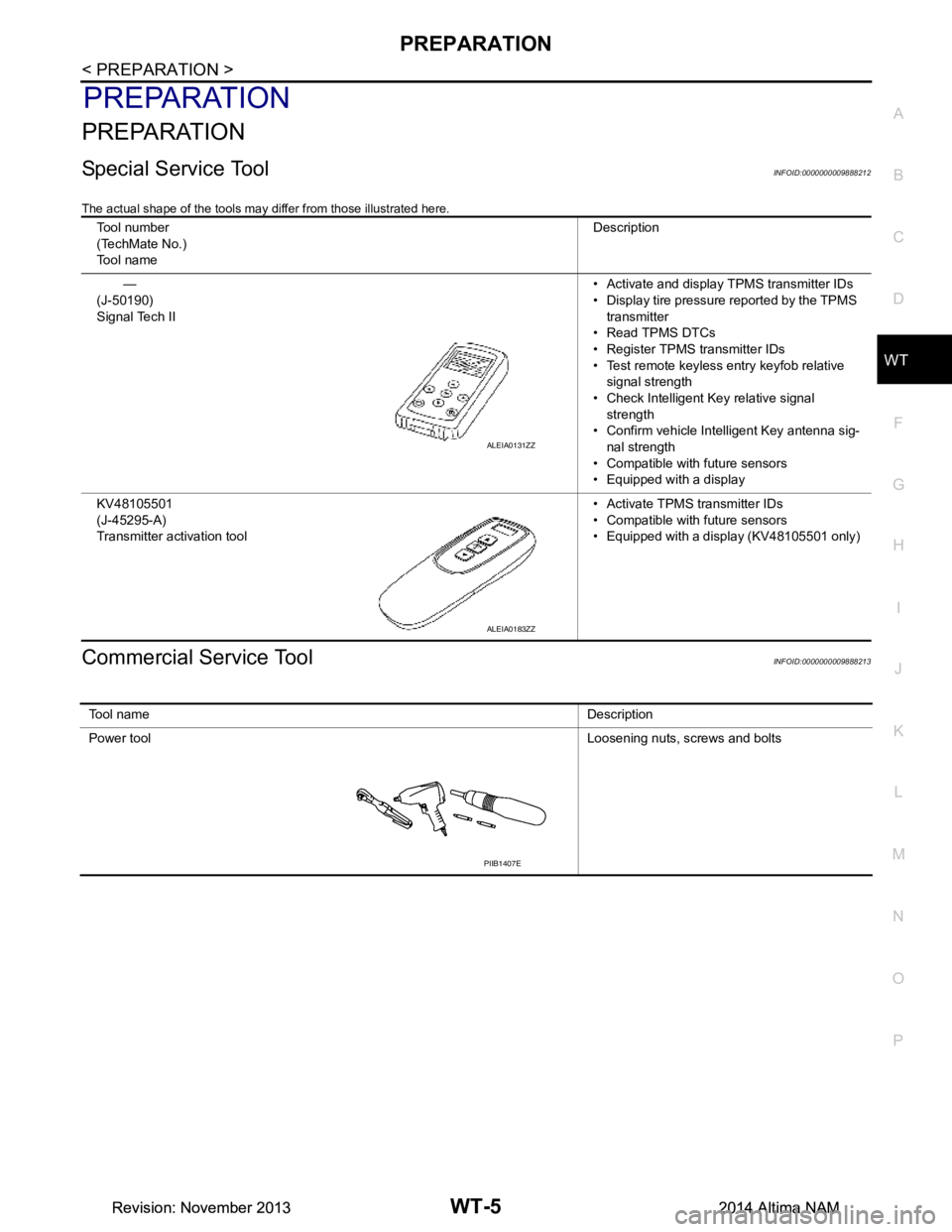
Special Service ToolINFOID:0000000009888212
The actual shape of the tools may di ffer from those illustrated here.
Commercial Service ToolINFOID:0000000009888213
Tool number
(TechMate No.)
Tool name Description
—
(J-50190)
Signal Tech II • Activate and display TPMS transmitter IDs
• Display tire pressure reported by the TPMS transmitter
• Read TPMS DTCs
• Register TPMS transmitter IDs
• Test remote keyless entry keyfob relative signal strength
• Check Intelligent Key relative signal strength
• Confirm vehicle Intelligent Key antenna sig-
nal strength
• Compatible with future sensors
• Equipped with a display
KV48105501
(J-45295-A)
Transmitter activation tool • Activate TPMS transmitter IDs
• Compatible with future sensors
• Equipped with a display (KV48105501 only)
ALEIA0131ZZ
ALEIA0183ZZ
To o l n a m e Description
Power tool Loosening nuts, screws and bolts
PIIB1407E
Revision: November 20132014 Altima NAMRevision: November 20132014 Altima NAM
Page 4681 of 4801

WT-6
< SYSTEM DESCRIPTION >
COMPONENT PARTS
SYSTEM DESCRIPTION
COMPONENT PARTS
Component Parts LocationINFOID:0000000009464476
Component DescriptionINFOID:0000000009464477
BCMINFOID:0000000009464478
The BCM reads the air pressure signal received by the remote keyless entry receiver. In addition, the BCM
also uses the outside key antennas (driver side, pass enger side and rear bumper) to identify the location of
the transmitters (if equipped with individual tire pressure display).
The BCM has a self-diagnosis function used to detect system malfunctions.
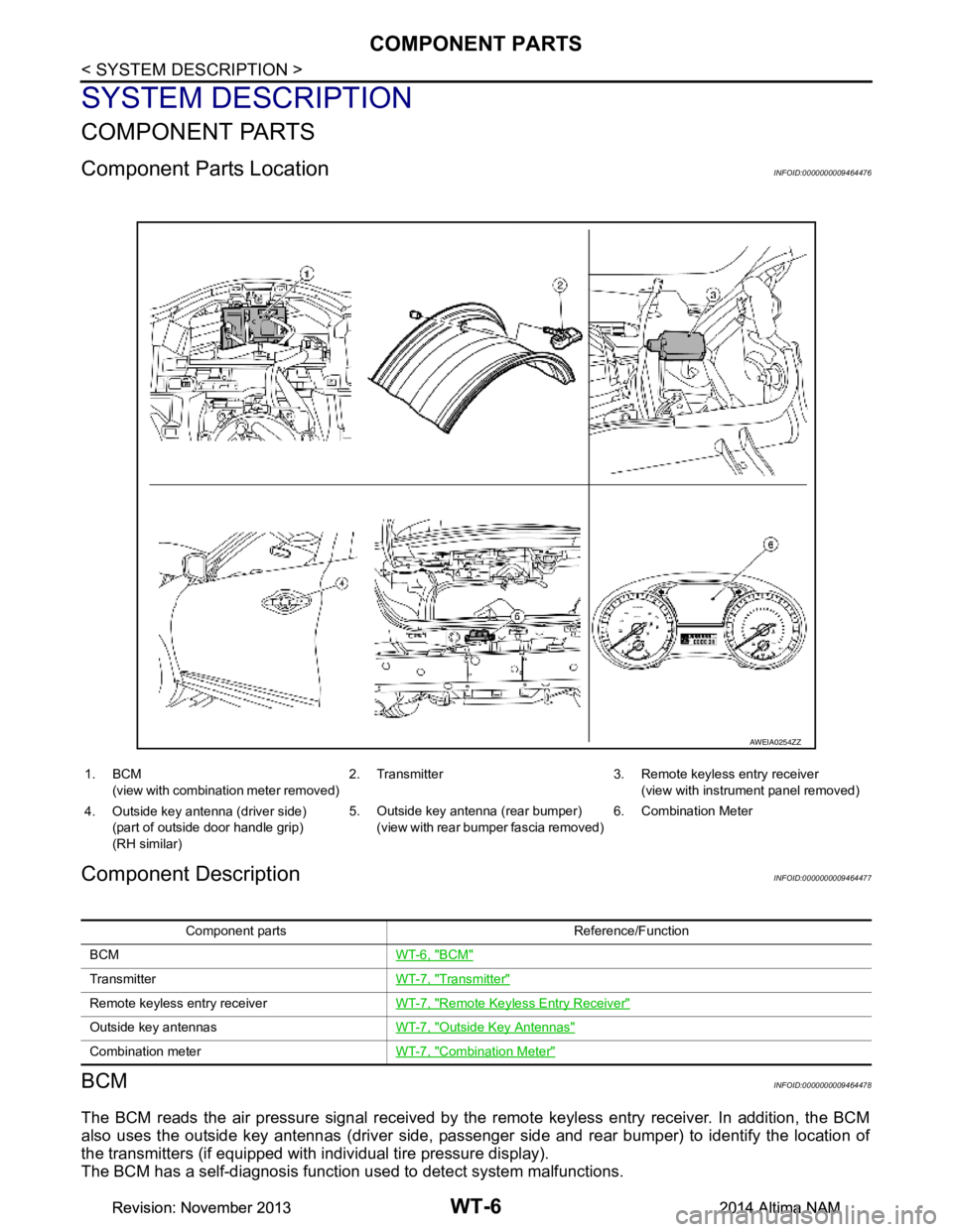
AWEIA0254ZZ
1. BCM
(view with combination meter removed) 2. Transmitter 3. Remote keyless entry receiver
(view with instrument panel removed)
4. Outside key antenna (driver side) (part of outside door handle grip)
(RH similar) 5. Outside key antenna (rear bumper)
(view with rear bumper fascia removed) 6. Combination Meter
Component parts Reference/Function
BCM WT-6, "BCM"
TransmitterWT-7, "Transmitter"
Remote keyless entry receiverWT-7, "Remote Keyless Entry Receiver"
Outside key antennasWT-7, "Outside Key Antennas"
Combination meterWT-7, "Combination Meter"
Revision: November 20132014 Altima NAMRevision: November 20132014 Altima NAM
Page 4682 of 4801

COMPONENT PARTSWT-7
< SYSTEM DESCRIPTION >
C
D
F
G H
I
J
K L
M A
B
WT
N
O P
TransmitterINFOID:0000000009464479
A sensor-transmitter integrated with a valve is instal led in each wheel, and transmits a detected air pressure
signal in the form of a radio wave. The radio signal is received by the remote keyless entry receiver.
Remote Keyless Entry ReceiverINFOID:0000000009464480
The remote keyless entry receiver receives the air pressure signal transmitted by the transmitter in each
wheel.
Outside Key AntennasINFOID:0000000009464481
For vehicles equipped with individual tire pressure display in the combination meter, the outside key antennas
(driver side, passenger side and rear bumper) are used by the BCM to identify the location of the transmitters.
Combination MeterINFOID:0000000009464482
The combination meter receives tire pressure status from the BCM via CAN communication. The combination
meter will display the low tire pressure warning lamp when a low tire pressure or system malfunction is
detected by the BCM. A warning message will also be displayed in the vehicle information display. Refer to the
Owner’s Manual for additional information.
Revision: November 20132014 Altima NAMRevision: November 20132014 Altima NAM