2014 NISSAN TEANA immobilizer
[x] Cancel search: immobilizerPage 3827 of 4801

SEC-2
WIRING DIAGRAM .....................................29
ENGINE START FUNCTION .......................... ...29
Wiring Diagram .................................................... ...29
NISSAN VEHICLE IMMOBILIZER SYSTEM-
NATS ............................................................... ...
40
Wiring Diagram .................................................... ...40
VEHICLE SECURITY SYSTEM .........................50
Wiring Diagram .................................................... ...50
BASIC INSPECTION ...................................63
DIAGNOSIS AND REPAIR WORK FLOW ..... ...63
Work Flow ............................................................ ...63
ADDITIONAL SERVICE WHEN REPLACING
CONTROL UNIT ............................................. ...
66
ECM ........................................................................ ...66
ECM : Description ...................................................66
ECM : Work Procedure ...........................................66
BCM ........................................................................ ...66
BCM : Description ...................................................66
BCM : Work Procedure ...........................................66
DTC/CIRCUIT DIAGNOSIS ...................... ...68
P1610 LOCK MODE ....................................... ...68
Description ........................................................... ...68
DTC Logic ...............................................................68
Diagnosis Procedure ..............................................68
P1611 ID DISCORD, IMMU-ECM ......................69
DTC Logic ............................................................ ...69
Diagnosis Procedure ..............................................69
P1612 CHAIN OF ECM-IMMU ...........................70
DTC Logic ............................................................ ...70
Diagnosis Procedure ..............................................70
P1614 CHAIN OF IMMU-KEY ...........................71
DTC Logic ............................................................ ...71
Diagnosis Procedure ..............................................71
B210B STARTER CONTROL RELAY ..............73
DTC Logic ............................................................ ...73
Diagnosis Procedure ..............................................73
B210C STARTER CONTROL RELAY ..............74
DTC Logic ............................................................ ...74
Diagnosis Procedure ..............................................74
B210D STARTER RELAY .................................76
DTC Logic ............................................................ ...76
Diagnosis Procedure ..............................................76
B210E STARTER RELAY .................................78
DTC Logic ............................................................ ...78
Diagnosis Procedure ..............................................78
B210F TRANSMISSION RANGE SWITCH .......80
Description ........................................................... ...80
DTC Logic ...............................................................80
Diagnosis Procedure ...............................................80
B2110 TRANSMISSION RANGE SWITCH .......82
Description ........................................................... ...82
DTC Logic ...............................................................82
Diagnosis Procedure ...............................................82
B2190 NATS ANTENNA AMP. .........................84
Description ........................................................... ...84
DTC Logic ...............................................................84
Diagnosis Procedure ...............................................84
B2191 DIFFERENCE OF KEY ..........................86
Description ........................................................... ...86
DTC Logic ...............................................................86
Diagnosis Procedure ...............................................86
B2192 ID DISCORD, IMMU-ECM ......................87
DTC Logic ............................................................ ...87
Diagnosis Procedure ...............................................87
B2193 CHAIN OF ECM-IMMU ..........................88
DTC Logic ............................................................ ...88
Diagnosis Procedure ...............................................88
B2195 ANTI-SCANNING ...................................89
DTC Logic ............................................................ ...89
Diagnosis Procedure ...............................................89
B2196 DONGLE UNIT .......................................90
Description ........................................................... ...90
DTC Logic ...............................................................90
Diagnosis Procedure ...............................................90
B2198 NATS ANTENNA AMP. .........................92
DTC Logic ............................................................ ...92
Diagnosis Procedure ...............................................92
B2555 STOP LAMP ...........................................94
DTC Logic ............................................................ ...94
Diagnosis Procedure ...............................................94
Component Inspection ............................................96
B2556 PUSH-BUTTON IGNITION SWITCH .....97
DTC Logic ............................................................ ...97
Diagnosis Procedure ...............................................97
Component Inspection ............................................98
B2557 VEHICLE SPEED ...................................99
DTC Logic ............................................................ ...99
Diagnosis Procedure ...............................................99
B2560 STARTER CONTROL RELAY ..............100
Description ........................................................... .100
DTC Logic .............................................................100
Diagnosis Procedure .............................................100
B2601 SHIFT POSITION ..................................101
DTC Logic ............................................................ .101
Revision: November 20132014 Altima NAMRevision: November 20132014 Altima NAM
Page 3828 of 4801

SEC-3
C
D E
F
G H
I
J
L
M A
B
SEC
N
O P
Diagnosis Procedure ...........................................
..
101
Component Inspection ..........................................103
B2602 SHIFT POSITION ..................................104
DTC Logic ........................................................... ..104
Diagnosis Procedure .............................................104
Component Inspection ..........................................105
B2603 SHIFT POSITION ..................................106
DTC Logic ........................................................... ..106
Diagnosis Procedure .............................................106
Component Inspection ..........................................109
B2604 SHIFT POSITION ..................................110
DTC Logic ........................................................... ..110
Diagnosis Procedure .............................................110
B2605 SHIFT POSITION ..................................113
DTC Logic ........................................................... ..113
Diagnosis Procedure .............................................113
B2608 STARTER RELAY ................................116
DTC Logic ........................................................... ..116
Diagnosis Procedure .............................................116
B2617 STARTER RELAY CIRCUIT .................118
Description .......................................................... ..118
DTC Logic .............................................................118
Diagnosis Procedure .............................................118
B261E VEHICLE TYPE .................................. ..120
Description .......................................................... ..120
DTC Logic .............................................................120
Diagnosis Procedure .............................................120
POWER SUPPLY AND GROUND CIRCUIT ....122
Diagnosis Procedure ........................................... ..122
POWER SUPPLY AND GROUND CIRCUIT ....123
Diagnosis Procedure ........................................... ..123
HEADLAMP FUNCTION ..................................124
Component Function Check ................................ ..124
Diagnosis Procedure .............................................124
HOOD SWITCH ................................................125
Component Function Check .............................. ..125
Diagnosis Procedure ............................................125
Component Inspection ..........................................126
SECURITY INDICATOR LAMP ........................127
Component Function Check .............................. ..127
Diagnosis Procedure ........................................... ..127
SYMPTOM DIAGNOSIS ............................129
ENGINE DOES NOT START WHEN INTELLI-
GENT KEY IS INSIDE OF VEHICLE ..............
129
Description ........................................................... ..129
Diagnosis Procedure .............................................129
SECURITY INDICATOR LAMP DOES NOT
TURN ON OR BL INK ......................................
130
Description ........................................................... ..130
Diagnosis Procedure .............................................130
VEHICLE SECURITY SYSTEM CANNOT BE
SET ..................................................................
131
INTELLIGENT KEY ................................................ ..131
INTELLIGENT KEY : Description ..........................131
INTELLIGENT KEY : Diagnos is Procedure ...........131
DOOR REQUEST SWITCH ................................... ..131
DOOR REQUEST SWITCH : Description .............131
DOOR REQUEST SWITCH : Diagnosis Proce-
dure ..................................................................... ..
131
DOOR KEY CYLINDER ......................................... ..132
DOOR KEY CYLINDER : Description ...................132
DOOR KEY CYLINDER : Diagnosis Procedure .. ..132
VEHICLE SECURITY ALARM DOES NOT
ACTIVATE .......................................................
133
Description ........................................................... ..133
Diagnosis Procedure .............................................133
PANIC ALARM FUNCTION DOES NOT OP-
ERATE .............................................................
134
Description ........................................................... ..134
Diagnosis Procedure .............................................134
REMOVAL AND INSTALLATION .............135
NATS ANTENNA AMP. ..................................135
Exploded View ..................................................... ..135
Removal and Installation .......................................135
PUSH BUTTON IGNITION SWITCH ...............136
Exploded View .......................................................136
Removal and Installation .......................................136
IMMOBILIZER CONTROL MODULE ..............137
Removal and Installation .......................................137
Revision: November 20132014 Altima NAMRevision: November 20132014 Altima NAM
Page 3835 of 4801

SEC-10
< SYSTEM DESCRIPTION >
COMPONENT PARTS
Push-button Ignition Switch
INFOID:0000000009461079
Push-button ignition switch detects that push-button is pressed and then transmits the signal to BCM. BCM
changes the power supply position with the operation of push-button ignition switch. BCM maintains the power
supply position status while push-button is not operated.
Security Indicator LampINFOID:0000000009461080
Security indicator lamp is located on combination meter.
Security indicator lamp blinks when power supply positi on is any position other than ON to warn that NISSAN
VEHICLE IMMOBILIZER SYSTEM-NATS [NVIS (NATS)] is on board.
Starter Control RelayINFOID:0000000009461081
Engine starting system functions by controlling both starter relay and starter control relay.
Both relays are integrated in IPDM E/R. Starter rela y is controlled by BCM and starter control relay is con-
trolled by IPDM E/R on request from BCM.
IPDM E/R transmits starter relay and starter control relay status signal to BCM via CAN communication.
Starter RelayINFOID:0000000009461082
Engine starting system functions by controlling both starter relay and starter control relay.
Both relays are integrated in IPDM E/R. Starter relay is controlled by BCM, and starter control relay is con-
trolled by IPDM E/R on request from BCM.
IPDM E/R transmits starter relay and starter control relay status signal to BCM via CAN communication.
Stop Lamp SwitchINFOID:0000000009461083
Stop lamp switch detects that brake pedal is depressed, and then transmits the signal to BCM.
Transmission Range SwitchINFOID:0000000009461084
Transmission range switch is integrated in CVT asse mbly, and detects the CVT shift selector position.
TCM receives the transmission range switch signal and then transmits the P/N position signal to BCM and
IPDM E/R.
BCM confirms the CVT shift selector position with the following 5 signals:
• P (Park) position signal from CVT shift selector (park position switch)
• P/N position signal from TCM
• P (Park) position signal from IPDM E/R (CAN)
• P/N position signal from IPDM E/R (CAN)
• P/N position signal from TCM (CAN)
IPDM E/R confirms the CVT shift sele ctor position with the following 3 signals:
• P (Park) position signal from CVT shift selector (park position switch)
• P/N position signal from TCM
• P/N position signal from BCM (CAN)
Vehicle Information DisplayINFOID:0000000009461085
Vehicle information display is integrated in combination meter.
Various information and warnings regarding t he Intelligent Key System are displayed.
Revision: November 20132014 Altima NAMRevision: November 20132014 Altima NAM
Page 3838 of 4801

SYSTEMSEC-13
< SYSTEM DESCRIPTION >
C
D E
F
G H
I
J
L
M A
B
SEC
N
O P
Vehicle speed: 4 km/h (2.5 MPH) or more
Emergency stop operation
• Press and hold the push-button ignition switch for 2 seconds or more.
• Press the push-button ignition switch 3 times or more within 1.5 seconds.
NISSAN VEHICLE IMMOBILIZER SYSTEM-NATS
Power supply position Engine start/stop condition
Push-button ignition switch
operation frequency
Selector lever Brake pedal operation
condition
LOCK → ACC — Not depressed 1
LOCK → ACC → ON — Not depressed 2
LOCK → ACC → ON → OFF — Not depressed 3
LOCK → START
ACC → START
ON → START P or N position Depressed 1
Engine is running → OFF — — 1
Power supply position Engine start/stop condition
Push-button ignition switch
operation frequency
Selector lever Brake pedal operation
condition
Engine is running → ACC — — Emergency stop operation
Engine stall return operation while
driving N position Not depressed 1
Revision: November 20132014 Altima NAMRevision: November 20132014 Altima NAM
Page 3839 of 4801

SEC-14
< SYSTEM DESCRIPTION >
SYSTEM
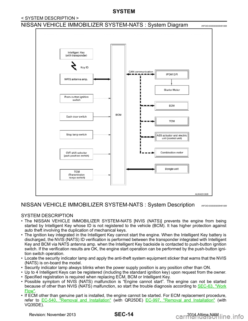
NISSAN VEHICLE IMMOBILIZER SY STEM-NATS : System Diagram
INFOID:0000000009461088
NISSAN VEHICLE IMMOBILIZER SYST EM-NATS : System DescriptionINFOID:0000000009461089
SYSTEM DESCRIPTION
• The NISSAN VEHICLE IMMOBILIZER SYSTEM-NATS [NVIS (NATS)] prevents the engine from being
started by Intelligent Key whose ID is not registered to the vehicle (BCM). It has higher protection against
auto theft involving the duplication of mechanical keys.
• The ignition key integrated in the Intelligent Key c annot start the engine. When the Intelligent Key battery is
discharged, the NVIS (NATS) ID verification is per formed between the transponder integrated with Intelligent
Key and BCM via NATS antenna amp. when the Intelligent Key backside is contacted to push-button ignition
switch. If the verification results are OK, the engine start operation can be performed by the push-button igni-
tion switch operation.
• Locate the security indicator lamp and apply the anti-t heft system equipment sticker that warns that the NVIS
(NATS) is on-board the model.
• Security indicator lamp always blinks when the pow er supply position is any position other than ON.
• Up to 4 Intelligent Keys can be registered (includi ng the standard ignition key) upon request from the owner.
• Specified registration is required when replacing ECM, BCM or Intelligent Key.
• Possible symptom of NVIS (NATS) malfunction is “Engine cannot start”. The engine can not be started
because of other than NVIS (NATS) malfunction, so start the trouble diagnosis according to SEC-63, "Work
Flow".
• If ECM other than genuine part is installed, the engi ne cannot be started. For ECM replacement procedure,
refer to EC-540, "Removal and Installation"
(with QR25DE) EC-997, "Removal and Installation" (with
VQ35DE).
ALKIA2513GB
Revision: November 20132014 Altima NAMRevision: November 20132014 Altima NAM
Page 3845 of 4801

SEC-20
< SYSTEM DESCRIPTION >
DIAGNOSIS SYSTEM (BCM)
DIAGNOSIS SYSTEM (BCM)
COMMON ITEM
COMMON ITEM : CONSULT Function (BCM - COMMON ITEM)INFOID:0000000009955724
CAUTION:
After disconnecting the CONSULT vehicle interface (VI) from the data link connector, the ignition must
be cycled OFF → ON (for at least 5 seconds) → OFF. If this step is not performed, the BCM may not go
to ”sleep mode”, potentially causing a di scharged battery and a no-start condition.
APPLICATION ITEM
CONSULT performs the following functions via CAN communication with BCM.
SYSTEM APPLICATION
BCM can perform the following functions.
Direct Diagnostic Mode Description
Ecu Identification The BCM part number is displayed.
Self Diagnostic Result The BCM self diagnostic results are displayed.
Data Monitor The BCM input/output data is displayed in real time.
Active Test The BCM activates outputs to test components.
Work support The settings for BCM functions can be changed.
Configuration • The vehicle specification can be read and saved.
• The vehicle specification can be written when replacing BCM.
CAN Diag Support Mntr The result of transmit/receive diagnosis of CAN communication is displayed.
System Sub System Direct Diagnostic Mode
Ecu Identification
Self Diagnostic Result
Data Monitor
Active Test
Work support
Configuration
CAN Diag Su pport Mntr
Door lock DOOR LOCK ××××
Rear window defogger REAR DEFOGGER ×××
Warning chime BUZZER ××
Interior room lamp timer INT LAMP ×××
Remote keyless entry system MULTI REMOTE ENT ×××
Exterior lamp HEADLAMP ×××
Wiper and washer WIPER ×××
Turn signal and hazard warning lamps FLASHER ××
Air conditioner AIR CONDITIONER ×
Intelligent Key system INTELLIGENT KEY ××××
Combination switch COMB SW ×
BCM BCM × × ×××
Immobilizer IMMU ×××
Interior room lamp battery saver BATTERY SAVER ××
Trunk open TRUNK ×
Vehicle security system THEFT ALM ×××
Revision: November 20132014 Altima NAMRevision: November 20132014 Altima NAM
Page 3865 of 4801

SEC-40
< WIRING DIAGRAM >
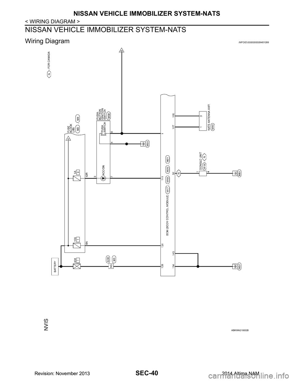
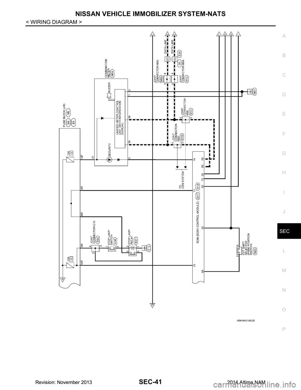
NISSAN VEHICLE IMMOBILIZER SYSTEM-NATS
NISSAN VEHICLE IMMOBILIZER SYSTEM-NATS
Wiring DiagramINFOID:0000000009461099
ABKWA2195GB
Revision: November 20132014 Altima NAMRevision: November 20132014 Altima NAM
Page 3866 of 4801

NISSAN VEHICLE IMMOBILIZER SYSTEM-NATSSEC-41
< WIRING DIAGRAM >
C
D E
F
G H
I
J
L
M A
B
SEC
N
O P
ABKWA2185GB
Revision: November 20132014 Altima NAMRevision: November 20132014 Altima NAM