2014 NISSAN TEANA key
[x] Cancel search: keyPage 3673 of 4801

RF-8
< SYSTEM DESCRIPTION >
DIAGNOSIS SYSTEM (BCM)
DIAGNOSIS SYSTEM (BCM)
COMMON ITEM
COMMON ITEM : CONSULT Function (BCM - COMMON ITEM)INFOID:0000000009941201
APPLICATION ITEM
CONSULT performs the following functions via CAN communication with BCM.
SYSTEM APPLICATION
BCM can perform the following functions.
RETAINED PWR
Direct Diagnostic Mode Description
Ecu Identification The BCM part number is displayed.
Self Diagnostic Result The BCM self diagnostic results are displayed.
Data Monitor The BCM input/output data is displayed in real time.
Active Test The BCM activates outputs to test components.
Work support The settings for BCM functions can be changed.
Configuration • The vehicle specification can be read and saved.
• The vehicle specification can be written when replacing BCM.
CAN Diag Support Mntr The result of transmit/receive diagnosis of CAN communication is displayed.
System Sub System Direct Diagnostic Mode
Ecu Identification
Self Diagnostic Result
Data Monitor
Active Test
Work support
Configuration
CAN Diag Support Mntr
Door lock DOOR LOCK ××××
Rear window defogger REAR DEFOGGER ×××
Warning chime BUZZER ××
Interior room lamp timer INT LAMP ×××
Remote keyless entry system MULTI REMOTE ENT ×××
Exterior lamp HEADLAMP ×××
Wiper and washer WIPER ×××
Turn signal and hazard warning lamps FLASHER ××
Air conditioner AIR CONDITIONER ×
Intelligent Key system INTELLIGENT KEY ××××
Combination switch COMB SW ×
BCM BCM × × ×××
Immobilizer IMMU ×××
Interior room lamp battery saver BATTERY SAVER ××
Trunk open TRUNK ×
Vehicle security system THEFT ALM ×××
RAP system RETAINED PWR ×
Signal buffer system SIGNAL BUFFER ×
Revision: November 20132014 Altima NAMRevision: November 20132014 Altima NAM
Page 3707 of 4801

RF-42
< REMOVAL AND INSTALLATION >
MOONROOF MOTOR ASSEMBLY
MOONROOF MOTOR ASSEMBLY
Removal and InstallationINFOID:0000000009461325
REMOVAL
1. Close glass lid.
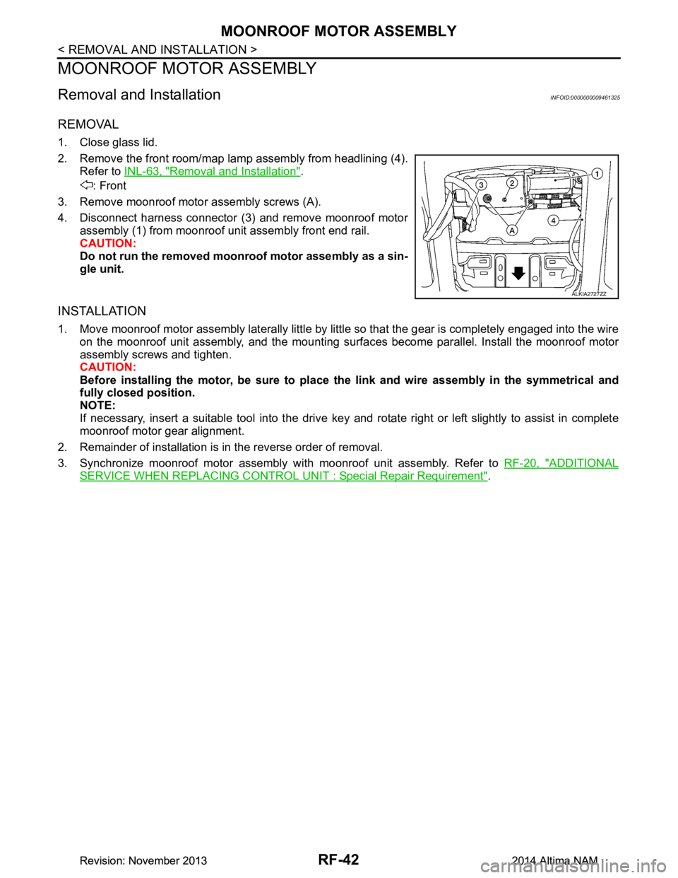
2. Remove the front room/map lamp assembly from headlining (4). Refer to INL-63, "Removal and Installation"
.
: Front
3. Remove moonroof motor assembly screws (A).
4. Disconnect harness connector (3) and remove moonroof motor assembly (1) from moonroof unit assembly front end rail.
CAUTION:
Do not run the removed mo onroof motor assembly as a sin-
gle unit.
INSTALLATION
1. Move moonroof motor assembly laterally little by little so that the gear is completely engaged into the wire
on the moonroof unit assembly, and the mounting surfaces become parallel. Install the moonroof motor
assembly screws and tighten.
CAUTION:
Before installing the motor, be sure to place the link and wire assembly in the symmetrical and
fully closed position.
NOTE:
If necessary, insert a suitable tool into the drive key and rotate right or left slightly to assist in complete
moonroof motor gear alignment.
2. Remainder of installation is in the reverse order of removal.
3. Synchronize moonroof motor assembly with moonroof unit assembly. Refer to RF-20, "ADDITIONAL
SERVICE WHEN REPLACING CONTROL UNIT : Special Repair Requirement".
ALKIA2727ZZ
Revision: November 20132014 Altima NAMRevision: November 20132014 Altima NAM
Page 3826 of 4801

SEC-1
BODY EXTERIOR, DOORS, ROOF & VEHICLE SECURITY
C
D E
F
G H
I
J
L
M
SECTION SEC
A
B
SEC
N
O P
CONTENTS
SECURITY CONTROL SYSTEM
PRECAUTION ................ ...............................4
PRECAUTIONS .............................................. .....4
Precaution for Supplemental Restraint System
(SRS) "AIR BAG" and "SEAT BELT PRE-TEN-
SIONER" ............................................................. ......
4
Precaution for Work ..................................................4
PREPARATION ............................................5
PREPARATION .............................................. .....5
Special Service Tool ........................................... ......5
SYSTEM DESCRIPTION ..............................6
COMPONENT PARTS ................................... .....6
Component Parts Location .................................. ......6
Component Description .............................................8
CVT Shift Selector (Park Position Switch) ................8
BCM ..........................................................................8
ECM ..........................................................................8
IPDM E/R ..................................................................9
NATS Antenna Amp. .................................................9
TCM ..........................................................................9
Combination Meter ....................................................9
Door Switch ...............................................................9
Outside Key Antenna ................................................9
Hood Switch ..............................................................9
Inside Key Antenna ...................................................9
Remote Keyless Entry Receiver ...............................9
Intelligent Key ............................................................9
Push-button Ignition Switch .....................................10
Security Indicator Lamp ...................................... ....10
Starter Control Relay ...............................................10
Starter Relay ...........................................................10
Stop Lamp Switch ...................................................10
Transmission Range Switch ....................................10
Vehicle Information Display .....................................10
SYSTEM .............................................................11
INTELLIGENT KEY SYSTEM/ENGINE START
FUNCTION ............................................................. ....
11
INTELLIGENT KEY SYSTEM/ENGINE START
FUNCTION : System Diagram ............................ ....
11
INTELLIGENT KEY SYSTEM/ENGINE START
FUNCTION : System Description ........................ ....
11
NISSAN VEHICLE IMMOBILIZER SYSTEM-NATS ....13
NISSAN VEHICLE IMMOBILIZER SYSTEM-
NATS : System Diagram ..................................... ....
14
NISSAN VEHICLE IMMOBILIZER SYSTEM-
NATS : System Description ................................. ....
14
VEHICLE SECURITY SYSTEM .................................16
VEHICLE SECURITY SYSTEM : System Dia-
gram .................................................................... ....
16
VEHICLE SECURITY SYSTEM : System Descrip-
tion ....................................................................... ....
16
DIAGNOSIS SYSTEM (BCM) ...........................20
COMMON ITEM ..................................................... ....20
COMMON ITEM : CONSULT Function (BCM -
COMMON ITEM) ................................................. ....
20
INTELLIGENT KEY ................................................ ....21
INTELLIGENT KEY : CONSULT Function (BCM -
INTELLIGENT KEY) ........... .....................................
21
THEFT ALM ........................................................... ....24
THEFT ALM : CONSULT Function (BCM - THEFT
ALM) .................................................................... ....
24
IMMU ...................................................................... ....25
IMMU : CONSULT Function (BCM - IMMU) ............25
DIAGNOSIS SYSTEM (IPDM E/R) ...................26
CONSULT Function (IPDM E/R) .............................26
ECU DIAGNOSIS INFORMATION ..............28
ECM, IPDM E/R, BCM .......................................28
List of ECU Reference ......................................... ....28
Revision: November 20132014 Altima NAMRevision: November 20132014 Altima NAM
Page 3827 of 4801

SEC-2
WIRING DIAGRAM .....................................29
ENGINE START FUNCTION .......................... ...29
Wiring Diagram .................................................... ...29
NISSAN VEHICLE IMMOBILIZER SYSTEM-
NATS ............................................................... ...
40
Wiring Diagram .................................................... ...40
VEHICLE SECURITY SYSTEM .........................50
Wiring Diagram .................................................... ...50
BASIC INSPECTION ...................................63
DIAGNOSIS AND REPAIR WORK FLOW ..... ...63
Work Flow ............................................................ ...63
ADDITIONAL SERVICE WHEN REPLACING
CONTROL UNIT ............................................. ...
66
ECM ........................................................................ ...66
ECM : Description ...................................................66
ECM : Work Procedure ...........................................66
BCM ........................................................................ ...66
BCM : Description ...................................................66
BCM : Work Procedure ...........................................66
DTC/CIRCUIT DIAGNOSIS ...................... ...68
P1610 LOCK MODE ....................................... ...68
Description ........................................................... ...68
DTC Logic ...............................................................68
Diagnosis Procedure ..............................................68
P1611 ID DISCORD, IMMU-ECM ......................69
DTC Logic ............................................................ ...69
Diagnosis Procedure ..............................................69
P1612 CHAIN OF ECM-IMMU ...........................70
DTC Logic ............................................................ ...70
Diagnosis Procedure ..............................................70
P1614 CHAIN OF IMMU-KEY ...........................71
DTC Logic ............................................................ ...71
Diagnosis Procedure ..............................................71
B210B STARTER CONTROL RELAY ..............73
DTC Logic ............................................................ ...73
Diagnosis Procedure ..............................................73
B210C STARTER CONTROL RELAY ..............74
DTC Logic ............................................................ ...74
Diagnosis Procedure ..............................................74
B210D STARTER RELAY .................................76
DTC Logic ............................................................ ...76
Diagnosis Procedure ..............................................76
B210E STARTER RELAY .................................78
DTC Logic ............................................................ ...78
Diagnosis Procedure ..............................................78
B210F TRANSMISSION RANGE SWITCH .......80
Description ........................................................... ...80
DTC Logic ...............................................................80
Diagnosis Procedure ...............................................80
B2110 TRANSMISSION RANGE SWITCH .......82
Description ........................................................... ...82
DTC Logic ...............................................................82
Diagnosis Procedure ...............................................82
B2190 NATS ANTENNA AMP. .........................84
Description ........................................................... ...84
DTC Logic ...............................................................84
Diagnosis Procedure ...............................................84
B2191 DIFFERENCE OF KEY ..........................86
Description ........................................................... ...86
DTC Logic ...............................................................86
Diagnosis Procedure ...............................................86
B2192 ID DISCORD, IMMU-ECM ......................87
DTC Logic ............................................................ ...87
Diagnosis Procedure ...............................................87
B2193 CHAIN OF ECM-IMMU ..........................88
DTC Logic ............................................................ ...88
Diagnosis Procedure ...............................................88
B2195 ANTI-SCANNING ...................................89
DTC Logic ............................................................ ...89
Diagnosis Procedure ...............................................89
B2196 DONGLE UNIT .......................................90
Description ........................................................... ...90
DTC Logic ...............................................................90
Diagnosis Procedure ...............................................90
B2198 NATS ANTENNA AMP. .........................92
DTC Logic ............................................................ ...92
Diagnosis Procedure ...............................................92
B2555 STOP LAMP ...........................................94
DTC Logic ............................................................ ...94
Diagnosis Procedure ...............................................94
Component Inspection ............................................96
B2556 PUSH-BUTTON IGNITION SWITCH .....97
DTC Logic ............................................................ ...97
Diagnosis Procedure ...............................................97
Component Inspection ............................................98
B2557 VEHICLE SPEED ...................................99
DTC Logic ............................................................ ...99
Diagnosis Procedure ...............................................99
B2560 STARTER CONTROL RELAY ..............100
Description ........................................................... .100
DTC Logic .............................................................100
Diagnosis Procedure .............................................100
B2601 SHIFT POSITION ..................................101
DTC Logic ............................................................ .101
Revision: November 20132014 Altima NAMRevision: November 20132014 Altima NAM
Page 3828 of 4801

SEC-3
C
D E
F
G H
I
J
L
M A
B
SEC
N
O P
Diagnosis Procedure ...........................................
..
101
Component Inspection ..........................................103
B2602 SHIFT POSITION ..................................104
DTC Logic ........................................................... ..104
Diagnosis Procedure .............................................104
Component Inspection ..........................................105
B2603 SHIFT POSITION ..................................106
DTC Logic ........................................................... ..106
Diagnosis Procedure .............................................106
Component Inspection ..........................................109
B2604 SHIFT POSITION ..................................110
DTC Logic ........................................................... ..110
Diagnosis Procedure .............................................110
B2605 SHIFT POSITION ..................................113
DTC Logic ........................................................... ..113
Diagnosis Procedure .............................................113
B2608 STARTER RELAY ................................116
DTC Logic ........................................................... ..116
Diagnosis Procedure .............................................116
B2617 STARTER RELAY CIRCUIT .................118
Description .......................................................... ..118
DTC Logic .............................................................118
Diagnosis Procedure .............................................118
B261E VEHICLE TYPE .................................. ..120
Description .......................................................... ..120
DTC Logic .............................................................120
Diagnosis Procedure .............................................120
POWER SUPPLY AND GROUND CIRCUIT ....122
Diagnosis Procedure ........................................... ..122
POWER SUPPLY AND GROUND CIRCUIT ....123
Diagnosis Procedure ........................................... ..123
HEADLAMP FUNCTION ..................................124
Component Function Check ................................ ..124
Diagnosis Procedure .............................................124
HOOD SWITCH ................................................125
Component Function Check .............................. ..125
Diagnosis Procedure ............................................125
Component Inspection ..........................................126
SECURITY INDICATOR LAMP ........................127
Component Function Check .............................. ..127
Diagnosis Procedure ........................................... ..127
SYMPTOM DIAGNOSIS ............................129
ENGINE DOES NOT START WHEN INTELLI-
GENT KEY IS INSIDE OF VEHICLE ..............
129
Description ........................................................... ..129
Diagnosis Procedure .............................................129
SECURITY INDICATOR LAMP DOES NOT
TURN ON OR BL INK ......................................
130
Description ........................................................... ..130
Diagnosis Procedure .............................................130
VEHICLE SECURITY SYSTEM CANNOT BE
SET ..................................................................
131
INTELLIGENT KEY ................................................ ..131
INTELLIGENT KEY : Description ..........................131
INTELLIGENT KEY : Diagnos is Procedure ...........131
DOOR REQUEST SWITCH ................................... ..131
DOOR REQUEST SWITCH : Description .............131
DOOR REQUEST SWITCH : Diagnosis Proce-
dure ..................................................................... ..
131
DOOR KEY CYLINDER ......................................... ..132
DOOR KEY CYLINDER : Description ...................132
DOOR KEY CYLINDER : Diagnosis Procedure .. ..132
VEHICLE SECURITY ALARM DOES NOT
ACTIVATE .......................................................
133
Description ........................................................... ..133
Diagnosis Procedure .............................................133
PANIC ALARM FUNCTION DOES NOT OP-
ERATE .............................................................
134
Description ........................................................... ..134
Diagnosis Procedure .............................................134
REMOVAL AND INSTALLATION .............135
NATS ANTENNA AMP. ..................................135
Exploded View ..................................................... ..135
Removal and Installation .......................................135
PUSH BUTTON IGNITION SWITCH ...............136
Exploded View .......................................................136
Removal and Installation .......................................136
IMMOBILIZER CONTROL MODULE ..............137
Removal and Installation .......................................137
Revision: November 20132014 Altima NAMRevision: November 20132014 Altima NAM
Page 3832 of 4801

COMPONENT PARTSSEC-7
< SYSTEM DESCRIPTION >
C
D E
F
G H
I
J
L
M A
B
SEC
N
O P
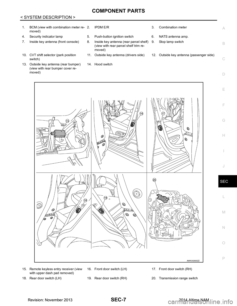
1. BCM (view with combination meter re- moved) 2. IPDM E/R 3. Combination meter
4. Security indicator lamp 5. Push-button ignition switch 6. NATS antenna amp.
7. Inside key antenna (front console) 8. Inside key antenna (rear parcel shelf) (view with rear parcel shelf trim re-
moved) 9. Stop lamp switch
10. CVT shift selector (park position switch) 11. Outside key antenna (drivers side) 12. Outside key antenna (passenger side)
13. Outside key antenna (rear bumper) (view with rear bumper cover re-
moved) 14. Hood switch
15. Remote keyless entry receiver (view with upper dash pad removed) 16. Front door switch (LH) 17. Front door switch (RH)
18. Rear door switch (LH) 19. Rear door switch (RH) 20. Transmission range switch
AWKIA2693ZZ
Revision: November 20132014 Altima NAMRevision: November 20132014 Altima NAM
Page 3833 of 4801

SEC-8
< SYSTEM DESCRIPTION >
COMPONENT PARTS
Component Description
INFOID:0000000009461065
CVT Shift Selector (P ark Position Switch)INFOID:0000000009461066
Park position switch detects that CVT shift selector is in the P (Park) position and then transmits the signal to
BCM and IPDM E/R.
BCM confirms the CVT shift selector position with the following 5 signals:
• P (Park) position signal from CVT shift selector (park position switch)
• P/N position signal from TCM
• P (Park) position signal from IPDM E/R (CAN)
• P/N position signal from IPDM E/R (CAN)
• P/N position signal from TCM (CAN)
IPDM E/R confirms the CVT shift sele ctor position with the following 3 signals:
• P (Park) position signal from CVT shift selector (park position switch)
• P/N position signal from TCM
• P/N position signal from BCM (CAN)
BCMINFOID:0000000009461067
BCM controls INTELLIGENT KE Y SYSTEM (ENGINE START FUNCTIO N), NISSAN VEHICLE IMMOBI-
LIZER SYSTEM-NATS [NVIS (NATS) ], and VEHICLE SECURITY SYSTEM.
BCM performs the ID verification between BCM and Intelligent Key when the Intelligent Key is carried into the
detection area of inside key antenna and push-button ignition swit ch is pressed. If the ID verification result is
OK, push-button ignition switch operation is available.
Then, when the power supply position is turned ON, BCM performs ID verification between BCM and ECM. If
the ID verification result is OK, ECM can start engine.
ECMINFOID:0000000009461068
ECM controls the engine.
When power supply position is turned ON, BCM starts communication with ECM and performs the ID verifica-
tion between BCM and ECM.
Component Reference
CVT shift selector (park position switch) SEC-8
BCMSEC-8
ECMSEC-8
IPDM E/RSEC-9
NATS antenna amp.SEC-9
TCMSEC-9
Combination meterSEC-9
Door switchSEC-9
Hood switchSEC-9
Outside key antennaSEC-9
Inside key antennaSEC-9
Intelligent KeySEC-9
Push-button ignition switchSEC-10
Remote keyless entry receiver SEC-9
Security indicator lampSEC-10
Starter control relaySEC-10
Starter relaySEC-10
Stop lamp switchSEC-10
Transmission range switchSEC-10
Vehicle information displaySEC-10
Revision: November 20132014 Altima NAMRevision: November 20132014 Altima NAM
Page 3834 of 4801

COMPONENT PARTSSEC-9
< SYSTEM DESCRIPTION >
C
D E
F
G H
I
J
L
M A
B
SEC
N
O P
If the verification result is OK, the engine can start. If the verification result is NG, the engine can not start.
IPDM E/RINFOID:0000000009461069
IPDM E/R has the starter relay and starter control relay inside. Starter relay and starter control relay are used
for the engine starting function. IPDM E/R contro ls these relays while communicating with BCM.
NATS Antenna Amp.INFOID:0000000009461070
The ID verification is performed between BCM and transponder in Intelligent Key via NATS antenna amp.
when Intelligent Key backside is contacted to push-button i gnition switch in case that Intelligent Key battery is
discharged. If the ID verification result is OK, the operation of starting engine is available.
TCMINFOID:0000000009461071
TCM transmits the shift position signal (P/N position) to BCM and IPDM E/R. And further, TCM transmits the
shift position signal (P/N position) to BCM via CAN communication.
BCM confirms the CVT shift selector position with the following 5 signals:
• P (Park) position signal from CVT shift selector (park position switch)
• P/N position signal from TCM
• P (Park) position signal from IPDM E/R (CAN)
• P/N position signal from IPDM E/R (CAN)
• P/N position signal from TCM (CAN)
IPDM E/R confirms the CVT shift select or position with the following 3 signals:
• P (Park) position signal from CVT shift selector (park position switch)
• P/N position signal from TCM
• P/N position signal from BCM (CAN)
Combination MeterINFOID:0000000009461072
Combination meter transmits the vehicle speed signal to BCM via CAN communication.
BCM also receives the vehicle speed signal from ABS ac tuator and electric unit (control unit) via CAN commu-
nication. BCM compares both signals to detect the vehicle speed.
Door SwitchINFOID:0000000009461073
Door switch detects door open/close conditi on and then transmits ON/OFF signal to BCM.
Outside Key AntennaINFOID:0000000009461074
Outside key antenna detects whether Intelligent Key is outside the vehicle and transmits the signal to BCM.
Three outside key antennas are installed in the front outside handle LH, front outside handle RH and rear
bumper.
Hood SwitchINFOID:0000000009461075
Hood switch detects that hood is open/closed, and then trans mits the signal to IPDM E/R. IPDM E/R transmits
hood switch signal to BCM via CAN communication.
Inside Key AntennaINFOID:0000000009461076
Inside key antenna detects whether Intelligent Key is inside the vehicle and transmits the signal to BCM.
Two inside key antennas are installed in the front console and rear parcel shelf.
Remote Keyless Entry ReceiverINFOID:0000000009461077
Remote keyless entry receiver receives each button oper ation signal and electronic key ID signal from Intelli-
gent Key and then transmits the signal to BCM.
Intelligent KeyINFOID:0000000009461078
Each Intelligent Key has an individual electronic ID and transmits the ID signal by request from BCM.
Carrying the Intelligent Key whose ID is registered in BCM, the driver can perform, remote start, door lock/
unlock operation, remote trunk, panic alarm and push-button ignition switch operation.
Revision: November 20132014 Altima NAMRevision: November 20132014 Altima NAM