2014 NISSAN TEANA ignition
[x] Cancel search: ignitionPage 4651 of 4801
WCS
DIAGNOSIS SYSTEM (METER)WCS-9
< SYSTEM DESCRIPTION >
C
D E
F
G H
I
J
K L
M B
A
O P
DIAGNOSIS SYSTEM (METER)
DescriptionINFOID:0000000009941189
COMBINATION METER SE LF-DIAGNOSIS MODE
The following meter functions can be checked during Combination Meter Self-Diagnosis Mode:
• Pointer sweep of speedometer, tachometer and gauges.
• Illumination of all LCD segments and color patterns for meter displays.
• Illumination of all lamps/LEDs that are controlled by the combination meter (regardless of switch status).
STARTING COMBINATION METER SELF-DIAGNOSIS MODE
NOTE:
• Check combination meter power supply and ground circuits if self-diagnosis mode does not start. Refer to
MWI-58, "COMBINATION METER : Diagnosis Procedure"
. Replace combination meter if power supply and
ground circuits are found to be normal and self-diagnosis mode does not start. Refer to MWI-82, "Removal
and Installation".
• Combination meter self-diagnosis mode will function with the ignition switch in ON. Combination meter self-
diagnosis mode will exit upon turning the ignition switch to OFF.
How to Initiate Se lf-Diagnosis Mode
1. Press and hold the trip reset switch while turning the ignition switch ON. After 2 seconds release trip reset
switch, then press the trip reset switch 3 times withi n 7 seconds after the ignition switch is turned ON.
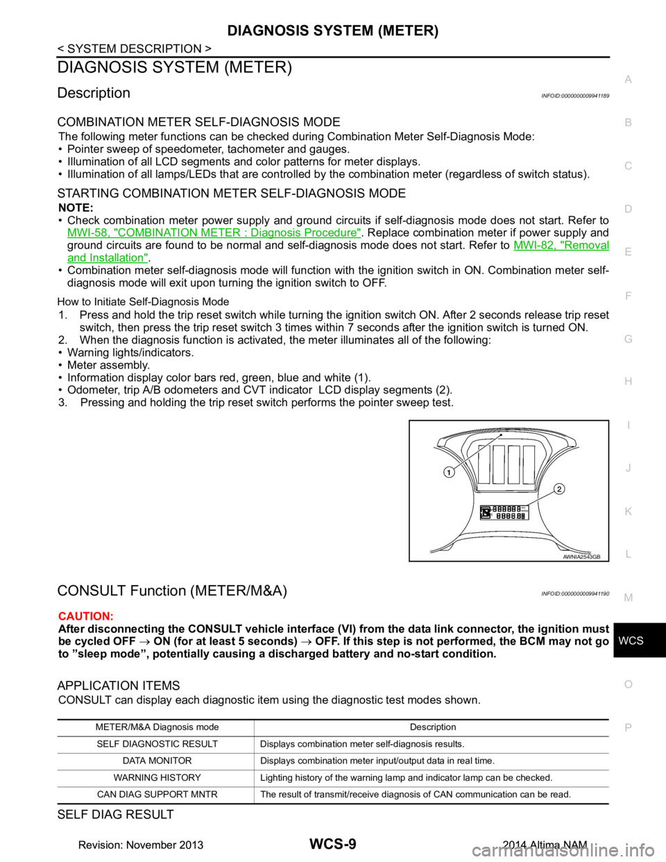
2. When the diagnosis function is activated, the meter illuminates all of the following:
• Warning lights/indicators.
• Meter assembly.
• Information display color bars red, green, blue and white (1).
• Odometer, trip A/B odometers and CVT indicator LCD display segments (2).
3. Pressing and holding the trip reset switch performs the pointer sweep test.
CONSULT Function (METER/M&A)INFOID:0000000009941190
CAUTION:
After disconnecting the CONSULT vehicle interface (VI) from the data link connector, the ignition must
be cycled OFF → ON (for at least 5 seconds) → OFF. If this step is not performed, the BCM may not go
to ”sleep mode”, potentiall y causing a discharged battery and no-start condition.
APPLICATION ITEMS
CONSULT can display each diagnostic item using the diagnostic test modes shown.
SELF DIAG RESULT
AWNIA2543GB
METER/M&A Diagnosis mode Description
SELF DIAGNOSTIC RESULT Displays combination meter self-diagnosis results. DATA MONITOR Displays combination meter input/output data in real time.
WARNING HISTORY Lighting history of the warning lamp and indicator lamp can be checked.
CAN DIAG SUPPORT MNTR The result of transmit/receive diagnosis of CAN communication can be read.
Revision: November 20132014 Altima NAMRevision: November 20132014 Altima NAM
Page 4655 of 4801

WCS
DIAGNOSIS SYSTEM (BCM)WCS-13
< SYSTEM DESCRIPTION >
C
D E
F
G H
I
J
K L
M B
A
O P
DIAGNOSIS SYSTEM (BCM)
COMMON ITEM
COMMON ITEM : CONSULT Function (BCM - COMMON ITEM)INFOID:0000000009941192
CAUTION:
After disconnecting the CONSULT vehicle interface (VI) from the data link connector, the ignition must
be cycled OFF → ON (for at least 5 seconds) → OFF. If this step is not performed, the BCM may not go
to ”sleep mode”, potentiall y causing a discharged battery and a no-start condition.
APPLICATION ITEM
CONSULT performs the following functions via CAN communication with BCM.
SYSTEM APPLICATION
BCM can perform the following functions.
Direct Diagnostic Mode Description
Ecu Identification The BCM part number is displayed.
Self Diagnostic Result The BCM self diagnostic results are displayed.
Data Monitor The BCM input/output data is displayed in real time.
Active Test The BCM activates outputs to test components.
Work support The settings for BCM functions can be changed.
Configuration • The vehicle specification can be read and saved.
• The vehicle specification can be written when replacing BCM.
CAN Diag Support Mntr The result of transmit/receive diagnosis of CAN communication is displayed.
System Sub System Direct Diagnostic Mode
Ecu Identification
Self Diagnostic Result
Data Monitor
Active Test
Work support
Configuration
CAN Diag Su pport Mntr
Door lock DOOR LOCK ××××
Rear window defogger REAR DEFOGGER ×××
Warning chime BUZZER ××
Interior room lamp timer INT LAMP ×××
Remote keyless entry system MULTI REMOTE ENT ×××
Exterior lamp HEADLAMP ×××
Wiper and washer WIPER ×××
Turn signal and hazard warning lamps FLASHER ××
Air conditioner AIR CONDITIONER ×
Intelligent Key system INTELLIGENT KEY ××××
Combination switch COMB SW ×
BCM BCM × × ×××
Immobilizer IMMU ×××
Interior room lamp battery saver BATTERY SAVER ××
Trunk open TRUNK ×
Vehicle security system THEFT ALM ×××
Revision: November 20132014 Altima NAMRevision: November 20132014 Altima NAM
Page 4656 of 4801

WCS-14
< SYSTEM DESCRIPTION >
DIAGNOSIS SYSTEM (BCM)
BUZZER
BUZZER : CONSULT Function (BCM - BUZZER)INFOID:0000000009941193
CAUTION:
After disconnecting the CONSULT vehicle interface (VI) from the data link connector, the ignition must
be cycled OFF → ON (for at least 5 seconds) → OFF. If this step is not performed, the BCM may not go
to ”sleep mode”, potentially causing a di scharged battery and a no-start condition.
DATA MONITOR
ACTIVE TEST
RAP system RETAINED PWR ×
Signal buffer system SIGNAL BUFFER ×
TPMS AIR PRESSURE MONITOR ××××
System Sub System
Direct Diagnostic Mode
Ecu Identification
Self Diagnostic Result
Data Monitor
Active Test
Work support
Configuration
CAN Diag Support Mntr
Monitor Item [Unit] Description
PUSH -SW [On/Off] Indicates condition of push-button ignition switch.
UNLK SEN -DR [On/Off] Indicates condition of door unlock sensor.
VEH SPEED 1 [km/h] Indicates vehicle speed signal received from ABS on CAN communication line.
TAIL LAMP SW [On/Off] Indicates condition of combination switch.
FR FOG SW [On/Off] Indicates condition of front fog lamp switch.
DOOR SW-DR [On/Off] Indicates condition of front door switch LH.
CDL LOCK SW [On/Off] Indicates condition of lock signal from door lock and unlock switch.
Test Item Description
SEAT BELT WARN TEST This test is able to check seat belt warning chime operation [On/Off].
LIGHT WARN ALM This test is able to check light warning chime operation [On/Off].
REVERSE WARNING This test is able to check reverse warning chime operation [On/Off].
ID REGIST WARNING This test is able to check TPMS transmitter ID regist warning chime operation [On/Off].
Revision: November 20132014 Altima NAMRevision: November 20132014 Altima NAM
Page 4667 of 4801
WCS
POWER SUPPLY AND GROUND CIRCUITWCS-25
< DTC/CIRCUIT DIAGNOSIS >
C
D E
F
G H
I
J
K L
M B
A
O P
DTC/CIRCUIT DIAGNOSIS
POWER SUPPLY AND GROUND CIRCUIT
COMBINATION METER
COMBINATION METER : Diagnosis ProcedureINFOID:0000000009941198
Regarding Wiring Diagram information, refer to MWI-32, "Wiring Diagram".
1.CHECK FUSES
Check that the following fuses are not blown.
Is the fuse blown?
YES >> Replace the blown fuse after repairing the affected circuit.
NO >> GO TO 2.
2.POWER SUPPLY CIRCUIT CHECK
1. Disconnect combination meter connector.
2. Check voltage between combination meter harnes s connector M24 terminals 5, 21, 22 and ground.
Is the inspection result normal?
YES >> GO TO 3.
NO >> Repair or replace harness or connectors.
3.GROUND CIRCUIT CHECK
1. Turn ignition switch OFF.
2. Check continuity between combination mete r harness connector M24 terminals 1, 2 and ground.
Is the inspection result normal?
YES >> Inspection End.
NO >> Repair or replace harness or connectors.
BCM (BODY CONTROL MODULE)
Unit Power source Fuse No.
Combination meter Battery 13
25
Ignition switch ON or START 31
Terminals Ignition switch position
(+) (–) OFF ACC ON START
Connector Terminal
M24 22
GroundBattery voltage Battery voltage Battery voltage Battery voltage
21 0V 0V Battery voltage Battery voltage 5 0V Battery voltage Battery voltage 0V
Te r m i n a l s Continuity
(+)
(–)
Connector Terminal
M24 1
Ground Yes
2
Revision: November 20132014 Altima NAMRevision: November 20132014 Altima NAM
Page 4670 of 4801
WCS-28
< DTC/CIRCUIT DIAGNOSIS >
SEAT BELT BUCKLE SWITCH SIGNAL CIRCUIT
SEAT BELT BUCKLE SWITCH SIGNAL CIRCUIT
DescriptionINFOID:0000000009462899
Transmits a seat belt buckle switch LH (driver seat) signal to the combination meter.
Component Function CheckINFOID:0000000009462900
1. CHECK COMBINATION METER INPUT SIGNAL
Select DATA MONITOR for METER/M&A and check the BUCKLE SW monitor value.
YES >> Inspection End.
NO >> Refer to WCS-28, "Diagnosis Procedure"
.
Diagnosis ProcedureINFOID:0000000009462901
Regarding Wiring Diagram information, refer to WCS-16, "Wiring Diagram".
1.CHECK COMBINATION METER INPUT SIGNAL
1. Turn ignition switch ON.
2. Check voltage between combination meter harness connector M24 terminal 9 and ground.
Is the inspection result normal?
YES >> Replace combination meter. Refer to MWI-82, "Removal and Installation".
NO >> GO TO 2.
2.CHECK SEAT BELT BUCKLE SWITCH CIRCUIT
1. Turn ignition switch OFF.
2. Disconnect combination meter harness connector M24 and seat belt buckle switch LH (driver seat) har-
ness connector B202.
3. Check continuity between combination meter harness connector M24 terminal 9 and seat belt buckle switch LH (driver seat) harness connector B202 terminal 1.
4. Check continuity between combination mete r harness connector M24 terminal 9 and ground.
Is the inspection result normal?
YES >> GO TO 3. BUCKLE SW
When seat belt LH (driver seat) is fastened : OFF
When seat belt LH (driver seat) is unfastened : ON
Combination meter
ConditionVo l ta g e
(Approx.)
Connector Te r m i n a l s
(+) (-)
M24 9 Ground When driver seat belt is fastened 12 V
When driver seat belt is unfastened 0 V
Combination meter Seat belt buckle switch LH (driver seat) Continuity
Connector Terminal Connector Terminal
M24 9 B202 1 Yes
Combination meter GroundContinuity
Connector Terminal
M24 9 No
Revision: November 20132014 Altima NAMRevision: November 20132014 Altima NAM
Page 4671 of 4801
WCS
SEAT BELT BUCKLE SWITCH SIGNAL CIRCUIT
WCS-29
< DTC/CIRCUIT DIAGNOSIS >
C
D E
F
G H
I
J
K L
M B
A
O P
NO >> Repair or replace harness or connectors.
3.CHECK SEAT BELT BUCKLE SWITCH GROUND CIRCUIT
Check harness continuity between seat belt buckle switch LH (driver seat) harness connector B202 terminal 2
and ground.
Is the inspection result normal?
YES >> Inspection End.
NO >> Repair or replace harness or connectors.
Component InspectionINFOID:0000000009462902
1. CHECK SEAT BELT BUCKLE SWITCH
1. Turn ignition switch OFF.
2. Disconnect the seat belt buckle switch LH (driver seat).
3. Check continuity between the seat belt buckl e switch LH (driver seat) terminals 1 and 2.
Is the inspection result normal?
YES >> Inspection End.
NO >> Replace the seat belt buckle switch LH (driver seat). Refer to SR-30, "Removal and Installation"
.
Seat belt buckle switch LH (driver seat)
GroundContinuity
Connector Terminal
B202 2 Yes
Terminal Condition Continuity
12 When seat belt is fastened No
When seat belt is unfastened Yes
Revision: November 20132014 Altima NAMRevision: November 20132014 Altima NAM
Page 4675 of 4801
WCS
THE SEAT BELT WARNING CONTINUES SOUNDING, OR DOES NOT SOUND
WCS-33
< SYMPTOM DIAGNOSIS >
C
D E
F
G H
I
J
K L
M B
A
O P
THE SEAT BELT WARNING CONTIN UES SOUNDING, OR DOES NOT
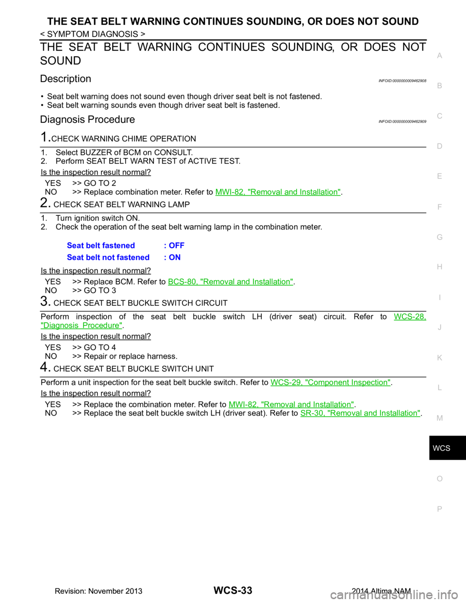
SOUND
DescriptionINFOID:0000000009462908
• Seat belt warning does not sound even though driver seat belt is not fastened.
• Seat belt warning sounds even though driver seat belt is fastened.
Diagnosis ProcedureINFOID:0000000009462909
1.CHECK WARNING CHIME OPERATION
1. Select BUZZER of BCM on CONSULT.
2. Perform SEAT BELT WARN TEST of ACTIVE TEST.
Is the inspection result normal?
YES >> GO TO 2
NO >> Replace combination meter. Refer to MWI-82, "Removal and Installation"
.
2. CHECK SEAT BELT WARNING LAMP
1. Turn ignition switch ON.
2. Check the operation of the seat belt warning lamp in the combination meter.
Is the inspection result normal?
YES >> Replace BCM. Refer to BCS-80, "Removal and Installation".
NO >> GO TO 3
3. CHECK SEAT BELT BUCKLE SWITCH CIRCUIT
Perform inspection of the seat belt buckle sw itch LH (driver seat) circuit. Refer to WCS-28,
"Diagnosis Procedure".
Is the inspection result normal?
YES >> GO TO 4
NO >> Repair or replace harness.
4. CHECK SEAT BELT BUCKLE SWITCH UNIT
Perform a unit inspection for the seat belt buckle switch. Refer to WCS-29, "Component Inspection"
.
Is the inspection result normal?
YES >> Replace the combination meter. Refer to MWI-82, "Removal and Installation".
NO >> Replace the seat belt buckle switch LH (driver seat). Refer to SR-30, "Removal and Installation"
.
Seat belt fastened : OFF
Seat belt not fastened : ON
Revision: November 20132014 Altima NAMRevision: November 20132014 Altima NAM
Page 4677 of 4801

WT-2
C1720, C1721, C1722, C1723 TRANSMITTER ...
37
DTC Logic ............................................................ ...37
Diagnosis Procedure ..............................................37
C1724, C1725, C1726, C1727 TRANSMITTER
(BATT VOLT) .................................................. ...
39
DTC Logic ............................................................ ...39
Diagnosis Procedure ..............................................39
C1729 VEHICLE SPEED SIGNAL ....................41
DTC Logic ............................................................ ...41
Diagnosis Procedure ..............................................41
C1730, C1731, C1732, C1733 FLAT TIRE ........42
DTC Logic ............................................................ ...42
Diagnosis Procedure ..............................................42
C1734 BCM ........................................................44
DTC Logic ............................................................ ...44
Diagnosis Procedure ..............................................44
C1735 IGNITION SIGNAL .................................46
DTC Logic ............................................................ ...46
Diagnosis Procedure ..............................................46
SYMPTOM DIAGNOSIS .............................48
TPMS .............................................................. ...48
Symptom Table ................................................... ...48
LOW TIRE PRESSURE WARNING LAMP
DOES NOT TURN ON .................................... ...
49
Low Tire Pressure Warning Lamp Does Not Come
On When Ignition Switch Is Turned On ............... ...
49
LOW TIRE PRESSURE WARNING LAMP
STAYS ON ...................................................... ...
50
Low Tire Pressure Warning Lamp Stays On When
Ignition Switch Is Turned On ................................ ...
50
EASY FILL TIRE ALERT DOES NOT ACTI-
VATE ............................................................... ...
51
Description ........................................................... ...51
Diagnosis Procedure ...............................................51
NOISE, VIBRATION AND HARSHNESS
(NVH) TROUBLESHOOTING ......................... ...
52
NVH Troubleshooting Chart ....................................52
PERIODIC MAINTENANCE .......................53
ROAD WHEEL ................................................ ...53
Inspection ............................................................. ...53
REMOVAL AND INSTALLATION ..............54
REMOTE KEYLESS ENTRY RECEIVER ...... ...54
Removal and Installation .........................................54
ROAD WHEEL TIRE ASSEMBLY ................. ...55
Adjustment ........................................................... ...55
UNIT REMOVAL AND INSTALLATION ....57
TIRE PRESSURE SENSOR ........................... ...57
Exploded View ..................................................... ...57
Removal and Installation .........................................57
SERVICE DATA AND SPECIFICATIONS
(SDS) ............... ...........................................
60
SERVICE DATA AND SPECIFICATIONS
(SDS) .............................................................. ...
60
Road Wheel ......................................................... ...60
Tire ..........................................................................60
Revision: November 20132014 Altima NAMRevision: November 20132014 Altima NAM