2014 NISSAN TEANA service reset
[x] Cancel search: service resetPage 3685 of 4801

RF-20
< BASIC INSPECTION >
INSPECTION AND ADJUSTMENT
INSPECTION AND ADJUSTMENT
ADDITIONAL SERVICE WHEN REPLACING CONTROL UNIT
ADDITIONAL SERVICE WHEN REPL ACING CONTROL UNIT : Description
INFOID:0000000009461301
MEMORY RESET PROCEDURE
1. Please observe the following instructi ons at confirming the moonroof operation.
NOTE:
Do not disconnect the electronic power while the moonroof is operating or within 5 seconds after the
moonroof stops. (to wipe-out the memory of lid position and operating friction.)
2. Initialization of system should be conducted after the following conditions. • When the moonroof motor is changed.
• When the moonroof does not operate normally. (Incomplete initialization conditions)
ADDITIONAL SERVICE WHEN REPLACING CONTROL UNIT : Special Repair Re-
quirement
INFOID:0000000009461302
INITIALIZATION PROCEDURE
If the moonroof does not open or clos e automatically, use the following procedure to return moonroof opera-
tion to normal.
NOTE:
If the moonroof switch is released at any time duri ng step 4, the procedure must be started over again. Leave
the ignition switch ON for at least 2 seconds after this procedure.
1. Push the ignition switch to the ON position.
2. Hold the moonroof switch in the tilt up position. Release the switch when the moonroof has reached the
full tilt up position.
3. Hold the moonroof switch in the tilt up position agai n. After a delay, the moonroof will backup. Release the
switch.
4. Within 4 seconds of releasing the switch in step 3, hold the moonroof switch in the tilt up position again.
The moonroof will move from the full tilt-up → slide-close → slide-open → slide-close → tilt-up → slide-
close. Release the switch, initialization is complete if the moonroof operates normally.
ANTI-PINCH FUNCTION
1. Fully open the moonroof to the full open position.
2. Place a piece of wood at the fully closed position.
3. Close the moonroof completely with auto-slide close function.
4. Moonroof should make contact and then tilt up in reverse for 100mm (3.94 in.) (approx.).
CAUTION:
• Do not test the anti-pinch functi on with your hands or other part of body parts because they may be
pinched.
• Depending on environment and drivin g conditions, if a similar impact or load is applied to the moon-
roof it may lower.
• Test the auto-slide operation before inspectio n when the system initialization is performed.
• Perform the initialization proced ure when the auto-slide operation or anti-pinch function does not
operate normally.
Revision: November 20132014 Altima NAMRevision: November 20132014 Altima NAM
Page 3779 of 4801

SE-30
< REMOVAL AND INSTALLATION >
FRONT SEAT
PASSENGER SIDE : Removal and Installation - Seat Assembly
INFOID:0000000009462938
REMOVAL
WARNING:
Do not leave any objects (screwdriver s, tools, etc.) on the seat during seat repair. It can lead to per-
sonal injury if the side air bag module should accidentally deploy.
CAUTION:
• When removing or installing the seat trim, handle it carefully to keep dirt out and to avoid damage.
• When checking the power seat circuit for continuity using a circuit tester, do not confuse its connec-
tor with the side air bag module connector. Such an error may cau se the air bag module to deploy.
• Do not drop, tilt, or bump the si de air bag module while installing the seat. Always handle it with
care.
• After front side air bag module inflates, the front seatback assembly must be replaced.
• When removing and installing the seat, use shop cloths to protect components from damage.
• Before removing the front seat, turn the ignition switch OFF, disconnect both battery cables and wait
at least three minutes.
1. Disconnect the negative and positive battery terminal s and wait at least three minutes. Refer to PG-73,
"Removal and Installation (Battery)".
2. Remove the headrest.
3. Slide the seat to the full rearward position.
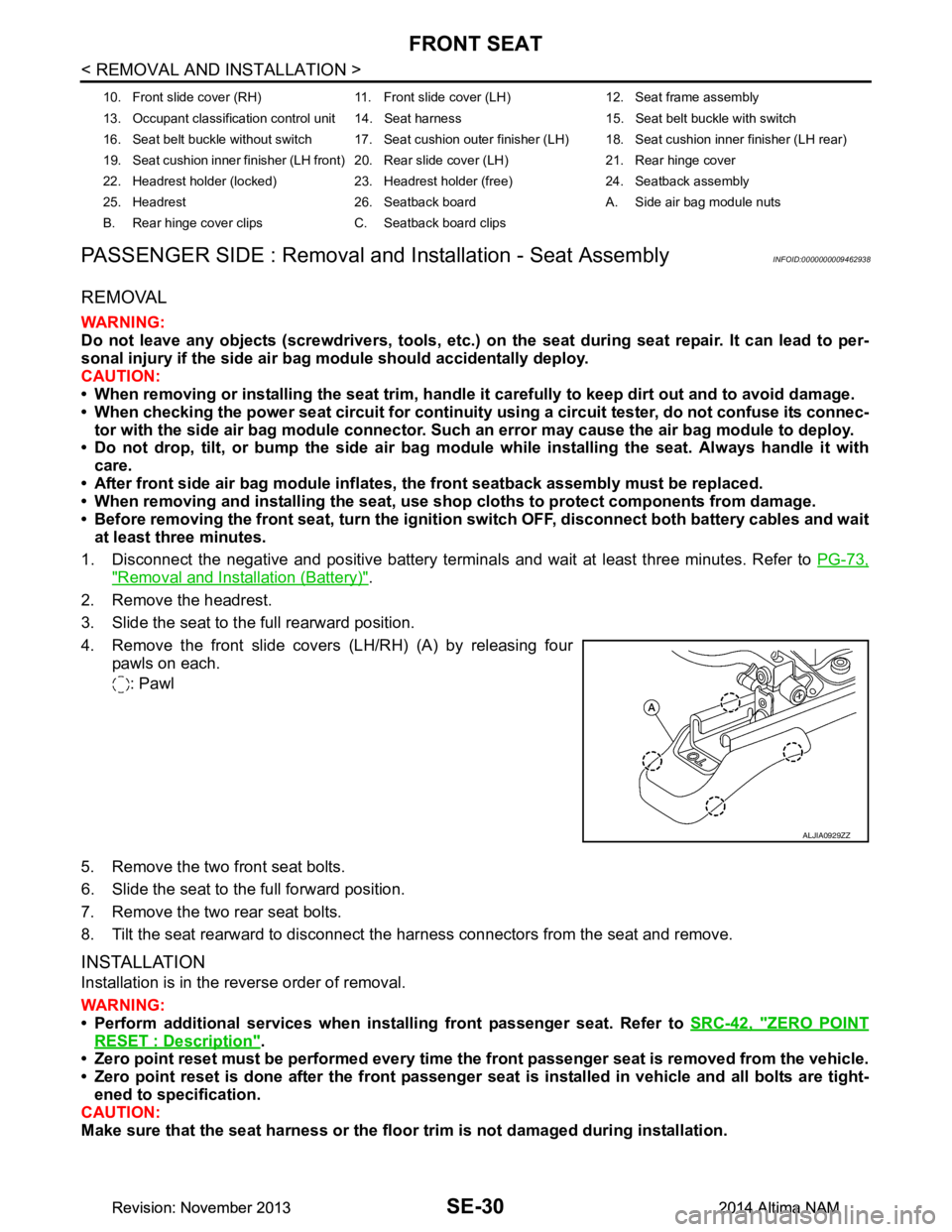
4. Remove the front slide covers (LH/RH) (A) by releasing four pawls on each.
: Pawl
5. Remove the two front seat bolts.
6. Slide the seat to the full forward position.
7. Remove the two rear seat bolts.
8. Tilt the seat rearward to disconnect the harness connectors from the seat and remove.
INSTALLATION
Installation is in the reverse order of removal.
WARNING:
• Perform additional services when instal ling front passenger seat. Refer to SRC-42, "ZERO POINT
RESET : Description".
• Zero point reset must be performed every time th e front passenger seat is removed from the vehicle.
• Zero point reset is done after the front passenger seat is installed in vehicle and all bolts are tight-
ened to specification.
CAUTION:
Make sure that the seat harness or the floor trim is not damaged during installation.
10. Front slide cover (RH) 11. Front sl ide cover (LH) 12. Seat frame assembly
13. Occupant classification control unit 14. Seat harness 15. Seat belt buckle with switch
16. Seat belt buckle without switch 17. Seat cushion outer finisher (LH) 18. Seat cushion inner finisher (LH rear)
19. Seat cushion inner finisher (LH front) 20. Rear slide cover (LH) 21. Rear hinge cover
22. Headrest holder (locked) 23. Headrest holder (free) 24. Seatback assembly
25. Headrest 26. Seatback board A. Side air bag module nuts
B. Rear hinge cover clips C. Seatback board clips
ALJIA0929ZZ
Revision: November 20132014 Altima NAMRevision: November 20132014 Altima NAM
Page 3994 of 4801

SRC-1
RESTRAINTS
C
D E
F
G
I
J
K L
M
SECTION SRC
A
B
SRC
N
O P
CONTENTS
SRS AIRBAG CONTROL SYSTEM
PRECAUTION ................ ...............................4
PRECAUTIONS .............................................. .....4
Precaution for Supplemental Restraint System
(SRS) "AIR BAG" and "SEAT BELT PRE-TEN-
SIONER" ............................................................. ......
4
Precaution for SRS "AIR BAG" and "SEAT BELT
PRE-TENSIONER" Service ................................ ......
4
SYSTEM DESCRIPTION ..............................5
COMPONENT PARTS ................................... .....5
Component Parts Location .................................. ......5
Component Description .............................................6
Driver Air Bag Module ...............................................7
Front Passenger Air Bag Module ..............................7
Front Side Air Bag Module .................................. ......7
Side Curtain Air Bag Module .....................................7
Front Seat Belt Pre-tensioner ....................................8
Air Bag Diagnosis Sensor Unit ..................................8
Crash Zone Sensor ...................................................8
Front Side Air Bag Satellite Sensor ...........................8
Rear Side Air Bag Satellite Sensor ...........................9
Front Door Satellite Sensor .......................................9
SRS Component Connectors ....................................9
SYSTEM .............................................................11
SRS AIR BAG SYSTEM ............................................11
SRS AIR BAG SYSTEM : Sy stem Diagram ............11
SRS AIR BAG SYSTEM : System Description ... ....11
OCCUPANT CLASSIFICATION SYSTEM ............ ....11
OCCUPANT CLASSIFICATION SYSTEM : Sys-
tem Diagram ........................................................ ....
12
OCCUPANT CLASSIFICATION SYSTEM : Sys-
tem Description ................................................... ....
12
SEAT BELT WARNING LAMP SYSTEM ..................13
SEAT BELT WARNING LAMP SYSTEM : System
Diagram ............................................................... ....
13
SEAT BELT WARNING LAMP SYSTEM : System
Description ........................................................... ....
14
DIAGNOSIS SYSTEM (AIR BAG) ....................15
Diagnosis Description ..............................................15
SRS Operation Check .............................................15
Trouble Diagnosis with CONSULT ..........................16
Trouble Diagnosis without CONSULT .....................17
SRS History Check ..................................................17
SRS Final Check .....................................................17
CONSULT Function (AIR BAG) ...............................17
CONSULT Function (OCCUPANT DETECTION) ....18
ECU DIAGNOSIS INFORMATION ..............19
DIAGNOSIS SENSOR UNIT .............................19
DTC Index ........................................................... ....19
Flash Code Index ....................................................23
WIRING DIAGRAM ......................................26
SRS AIR BAG SYSTEM ...................................26
Wiring Diagram .................................................... ....26
BASIC INSPECTION ...................................40
DIAGNOSIS AND REPAIR WORK FLOW .......40
Work Flow ............................................................ ....40
INSPECTION AND ADJUSTMENT ..................42
ADDITIONAL SERVICE WHEN REPLACING
CONTROL UNIT .................................................... ....
42
ADDITIONAL SERVICE WHEN REPLACING
CONTROL UNIT : Description ............................. ....
42
ADDITIONAL SERVICE WHEN REPLACING
CONTROL UNIT : Special Repair Requirement .. ....
42
ZERO POINT RESET ............................................. ....42
ZERO POINT RESET : Description .........................42
ZERO POINT RESET : Special Repair Require-
ment ..................................................................... ....
42
Revision: November 20132014 Altima NAMRevision: November 20132014 Altima NAM
Page 4035 of 4801

SRC-42
< BASIC INSPECTION >
INSPECTION AND ADJUSTMENT
INSPECTION AND ADJUSTMENT
ADDITIONAL SERVICE WHEN REPLACING CONTROL UNIT
ADDITIONAL SERVICE WHEN REPL ACING CONTROL UNIT : Description
INFOID:0000000009460735
WARNING:
Always perform zero point reset using CONSULT when removing an d installing the front passenger
seat or servicing the occupant classification system. If zero point reset is not performed, the OCS may
not operate normally, which may increase the risk of serious injury in a collision.
ADDITIONAL SERVICE WHEN REPLACING CONTROL UNIT : Special Repair Re-
quirement
INFOID:0000000009460736
WORK PROCEDURE WHEN REPLACING OCS CONTROL UNIT
1.PERFORM ZERO POINT RESET
Perform zero point reset. Refer to SRC-42, "ZERO POINT RESET : Special Repair Requirement"
.
>> Inspection End.
ZERO POINT RESET
ZERO POINT RESET : DescriptionINFOID:0000000009460737
Zero point reset is an initializing procedure for the OCS (weight) sensors that must be performed using CON-
SULT when removing and installing passenger seat or servic ing the OCS system. If zero point reset is not per-
formed, the initialization is incomplete and OCS may not operate normally.
NOTE:
• When reinstalling the passenger seat, the initial value for the OCS sensors may change, and the OCS may
not operate normally.
• When zero point reset is performed after removal and installation of passenger seat, CONSULT displays "complete".
ZERO POINT RESET : Spec ial Repair RequirementINFOID:0000000009460738
1.PERFORM ZERO POINT RESET
1. Perform preliminary checks: NOTE:
• Level the vehicle
• Minimize vibrations near the vehicle
• Remove any objects on passenger seat
• Do not touch the vehicle during zero point reset
2. Select START on ZERO POINT RESET from , WORK SUPPORT of “OCCUPANT DETECTION”.
3. “Zero point reset” starts.
>> GO TO 2.
2.CONFIRM RESET
1. Check that "Complete" is displayed on “Zero point reset status”.
CAUTION:
• “Complete” may be displayed if the seat has been reinstalled, or “zero point reset” has already been
performed.
• "Incomplete” may be displayed if a new seat is installed.
• Air bag warning lamp flashes in user mode if zero point reset is "incomplete".
Is zero point reset status "complete"?
YES >> Print out “ZERO POINT RESET CURRENT STATUS” screen. Inspection end.
NO >> Recheck the preliminary check items and perform zero point reset again.
Revision: November 20132014 Altima NAMRevision: November 20132014 Altima NAM