2014 NISSAN TEANA radio
[x] Cancel search: radioPage 2556 of 4801
GI-28
< PRECAUTION >
PRECAUTIONS
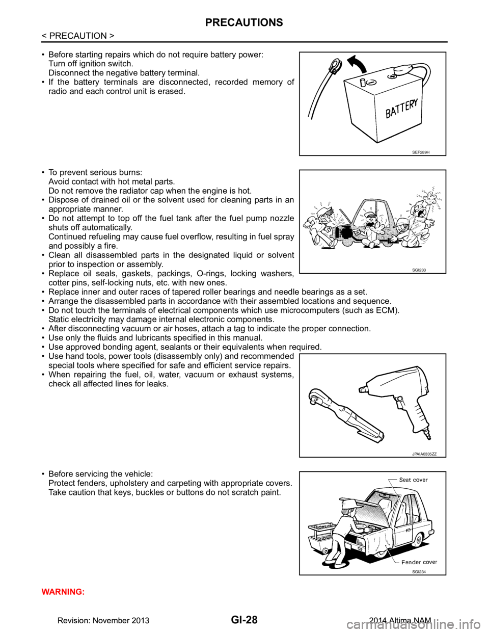
• Before starting repairs which do not require battery power:Turn off ignition switch.
Disconnect the negative battery terminal.
• If the battery terminals are disconnected, recorded memory of
radio and each control unit is erased.
• To prevent serious burns: Avoid contact with hot metal parts.
Do not remove the radiator cap when the engine is hot.
• Dispose of drained oil or the solvent used for cleaning parts in an
appropriate manner.
• Do not attempt to top off the fuel tank after the fuel pump nozzle
shuts off automatically.
Continued refueling may cause fuel overflow, resulting in fuel spray
and possibly a fire.
• Clean all disassembled parts in the designated liquid or solvent
prior to inspection or assembly.
• Replace oil seals, gaskets, packings, O-rings, locking washers, cotter pins, self-locking nuts, etc. with new ones.
• Replace inner and outer races of tapered roller bearings and needle bearings as a set.
• Arrange the disassembled parts in accordance with their assembled locations and sequence.
• Do not touch the terminals of electrical com ponents which use microcomputers (such as ECM).
Static electricity may damage internal electronic components.
• After disconnecting vacuum or air hoses, atta ch a tag to indicate the proper connection.
• Use only the fluids and lubricants specified in this manual.
• Use approved bonding agent, sealants or their equivalents when required.
• Use hand tools, power tools (disassembly only) and recommended special tools where specified for safe and efficient service repairs.
• When repairing the fuel, oil, water, vacuum or exhaust systems,
check all affected lines for leaks.
• Before servicing the vehicle: Protect fenders, upholstery and carpeting with appropriate covers.
Take caution that keys, buckles or buttons do not scratch paint.
WARNING:
SEF289H
SGI233
JPAIA0335ZZ
SGI234
Revision: November 20132014 Altima NAMRevision: November 20132014 Altima NAM
Page 2567 of 4801
SERVICE INFORMATION FOR ELECTRICAL INCIDENTGI-39
< BASIC INSPECTION >
C
D E
F
G H
I
J
K L
M B
GI
N
O PBASIC INSPECTION
SERVICE INFORMATION FO R ELECTRICAL INCIDENT
Work FlowINFOID:0000000009463011
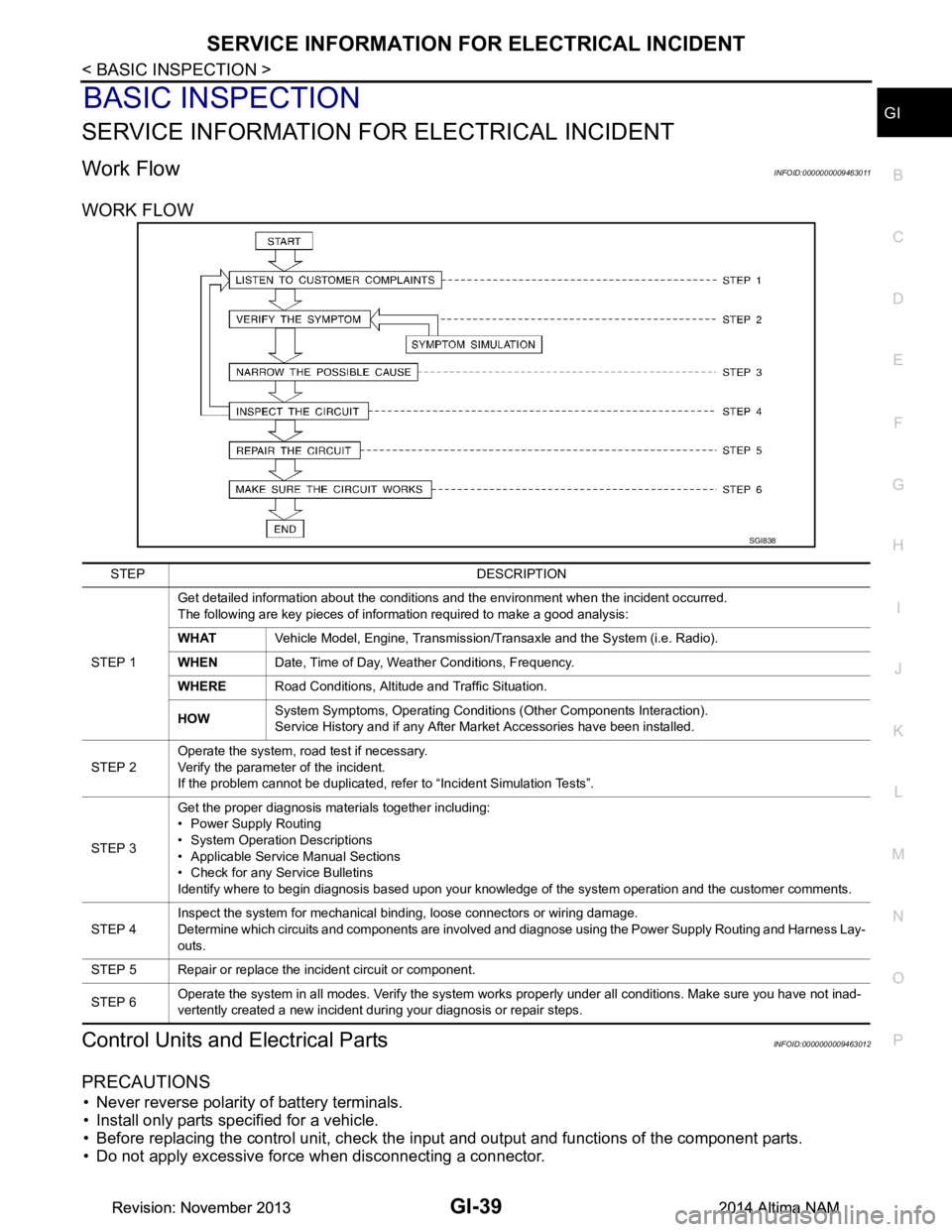
WORK FLOW
Control Units and Electrical PartsINFOID:0000000009463012
PRECAUTIONS
• Never reverse polarity of battery terminals.
• Install only parts specified for a vehicle.
• Before replacing the control unit, check the i nput and output and functions of the component parts.
• Do not apply excessive force when disconnecting a connector.
SGI838
STEP DESCRIPTION
STEP 1 Get detailed information about the conditions and the environment when the incident occurred.
The following are key pieces of information required to make a good analysis:
WHAT Vehicle Model, Engine, Transmission/Transaxle and the System (i.e. Radio).
WHEN Date, Time of Day, Weather Conditions, Frequency.
WHERE Road Conditions, Altitude and Traffic Situation.
HOW System Symptoms, Operating Conditions (Other Components Interaction).
Service History and if any After Market Accessories have been installed.
STEP 2 Operate the system, road test if necessary.
Verify the parameter of the incident.
If the problem cannot be duplicated, refer to “Incident Simulation Tests”.
STEP 3 Get the proper diagnosis materials together including:
• Power Supply Routing
• System Operation Descriptions
• Applicable Service Manual Sections
• Check for any Service Bulletins
Identify where to begin diagnosis based upon your knowledge of the system operation and the customer comments.
STEP 4 Inspect the system for mechanical binding, loose connectors or wiring damage.
Determine which circuits and components are involved and diagnose using the Power Supply Routing and Harness Lay-
outs.
STEP 5 Repair or replace the incident circuit or component.
STEP 6 Operate the system in all modes. Verify the system works properly under all conditions. Make sure you have not inad-
vertently created a new incident during your diagnosis or repair steps.
Revision: November 20132014 Altima NAMRevision: November 20132014 Altima NAM
Page 2573 of 4801
SERVICE INFORMATION FOR ELECTRICAL INCIDENTGI-45
< BASIC INSPECTION >
C
D E
F
G H
I
J
K L
M B
GI
N
O P
An unclamped or loose harness can cause wiring to be pinched by seat components (such as slide guides)
during vehicle vibration. If the wiring runs under s eating areas, inspect wire routing for possible damage or
pinching.
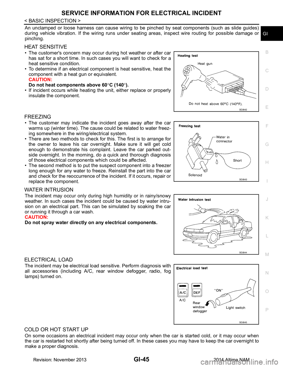
HEAT SENSITIVE
• The customer's concern may occur during hot weather or after car has sat for a short time. In such cases you will want to check for a
heat sensitive condition.
• To determine if an electrical component is heat sensitive, heat the component with a heat gun or equivalent.
CAUTION:
Do not heat components above 60 °C (140 °).
• If incident occurs while heating t he unit, either replace or properly
insulate the component.
FREEZING
• The customer may indicate the incident goes away after the car warms up (winter time). The cause could be related to water freez-
ing somewhere in the wiring/electrical system.
• There are two methods to check for this. The first is to arrange for the owner to leave his car overnight. Make sure it will get cold
enough to demonstrate his complaint. Leave the car parked out-
side overnight. In the morning, do a quick and thorough diagnosis
of those electrical components which could be affected.
• The second method is to put the suspect component into a freezer long enough for any water to freeze. Reinstall the part into the car
and check for the reoccurrence of the incident. If it occurs, repair or
replace the component.
WATER INTRUSION
The incident may occur only during high humidity or in rainy/snowy
weather. In such cases the incident could be caused by water intru-
sion on an electrical part. This c an be simulated by soaking the car
or running it through a car wash.
CAUTION:
Do not spray water directly on any electrical components.
ELECTRICAL LOAD
The incident may be electrical load sensitive. Perform diagnosis with
all accessories (including A/C, rear window defogger, radio, fog
lamps) turned on.
COLD OR HOT START UP
On some occasions an electrical incident may occur only when the car is started cold, or it may occur when
the car is restarted hot shortly after being turned off. In these cases you may have to keep the car overnight to
make a proper diagnosis.
SGI842
SGI843
SGI844
SGI845
Revision: November 20132014 Altima NAMRevision: November 20132014 Altima NAM
Page 3439 of 4801

PG
INSPECTION AND ADJUSTMENTPG-7
< BASIC INSPECTION >
C
D E
F
G H
I
J
K L
B
A
O P
N
INSPECTION AND ADJUSTMENT
ADDITIONAL SERVICE WHEN REMOVI
NG BATTERY NEGATIVE TERMINAL
ADDITIONAL SERVICE WHEN REMOVING BATTERY NEGATIVE TERMINAL : Spe-
cial Repair Requirement
INFOID:0000000009460434
Required Procedure After Battery Disconnection
System Item Reference
Engine Control System Idle Air Volume Learning EC-179
(QR25DE)
EC-683
(VQ35DE)
Power Window Control System Power Window System Initialization PWC-27
(LH Only Anti-Pinch)
PWC-93
(LH & RH Front Anti-Pinch)
Roof Moonroof Memory Reset/Initialization RF-20
Heater & Air Conditioning Control SystemTemperature Setting Trimmer
HAC-50
(Automatic Air Conditioner)
Foot Position Setting Trimmer HAC-50
(Automatic Air Conditioner)
Inlet Port Memory Function (FRE) HAC-50
(Automatic Air Conditioner)
Inlet Port Memory Function (REC) HAC-51
(Automatic Air Conditioner)
Target Evaporator Temp Upper Limit HAC-51
(Automatic Air Conditioner)
Audio, Visual & Navigation System Audio (Radio Preset) Refer to Owner's Manual.
Navigation System Refer to Owner's Manual.
Revision: November 20132014 Altima NAM
Page 4678 of 4801
PRECAUTIONSWT-3
< PRECAUTION >
C
D
F
G H
I
J
K L
M A
B
WT
N
O P
PRECAUTION
PRECAUTIONS
Precaution for Supplemental Restraint System (SRS) "AIR BAG" and "SEAT BELT
PRE-TENSIONER"
INFOID:0000000009951708
The Supplemental Restraint System such as “A IR BAG” and “SEAT BELT PRE-TENSIONER”, used along
with a front seat belt, helps to reduce the risk or severi ty of injury to the driver and front passenger for certain
types of collision. Information necessary to service t he system safely is included in the SR and SB section of
this Service Manual.
WARNING:
• To avoid rendering the SRS inoper ative, which could increase the risk of personal injury or death in
the event of a collision which would result in air bag inflation, all maintenance must be performed by
an authorized NISSAN/INFINITI dealer.
• Improper maintenance, including in correct removal and installation of the SRS, can lead to personal
injury caused by unintentional act ivation of the system. For removal of Spiral Cable and Air Bag
Module, see the SR section.
• Do not use electrical test equipm ent on any circuit related to the SRS unless instructed to in this
Service Manual. SRS wiring harnesses can be identi fied by yellow and/or orange harnesses or har-
ness connectors.
PRECAUTIONS WHEN USING POWER TOOLS (AIR OR ELECTRIC) AND HAMMERS
WARNING:
• When working near the Airbag Diagnosis Sensor Un it or other Airbag System sensors with the Igni-
tion ON or engine running, DO NOT use air or el ectric power tools or strike near the sensor(s) with a
hammer. Heavy vibration could activate the sensor( s) and deploy the air bag(s), possibly causing
serious injury.
• When using air or electric power tools or hammers , always switch the Ignition OFF, disconnect the
battery and wait at least three mi nutes before performing any service.
Service Notice and Precautions for TPMSINFOID:0000000009464472
WARNING:
Radio waves could adversely affect electrical medi cal equipment. Those who use a pacemaker should
contact the electrical medical equipment manu facturer for possible influences before use.
• Low tire pressure warning lamp blinks for 1 minute, then turns ON when any malfunction occurs except low
tire pressure. Erase the self-diagnosis memories for Tire Pressure Monitoring System (TPMS), or register
the ID to turn low tire pressure warning lamp OFF. For ID registration, refer to WT-25, "Work Procedure"
.
• ID registration is required when replacing or rotating wheels, replacing tire pressure sensor or BCM. Refer to WT-25, "Work Procedure"
.
• For easy fill tire alert function, refer to the following. WT-9, "Easy Fill Tire Alert Function"
- When inflating the tires, park the vehicle in the safe area and ensure the safety of the working area.
- Read and understand the easy fill tire alert function prior to use.
- Inflate the tires one at a time.
- If there is no response for approximately 15 seconds or mo re after inflating the tires, cancel the use of the
easy fill tire alert function or move the vehicle approximately 1 m (3.2 ft) backward or forward to try again.
The air filler pressure may be weak or out of service area.
- Despite the high-precision TPMS pressure sensor, an i ndicated value may differ from that of the pressure
gauge.
- Air pressure is measured rather high due to the rise in tire air temperature after driving.
- If TPMS is malfunctioning, the easy fill tire alert is unusable.
• Replace grommet seal, valve core and valve cap of tire pressure sensor in TPMS when replacing each tire
by reaching the wear limit. Refer to WT-57, "Exploded View"
.
• Because the tire pressure sensor conforms to No rth America radio law, the following items must be
observed.
- The sensor may be used only in North America.
- It may not be used in any method other than the specified method.
- It must not be disassembled or modified.
Revision: November 20132014 Altima NAMRevision: November 20132014 Altima NAM
Page 4682 of 4801

COMPONENT PARTSWT-7
< SYSTEM DESCRIPTION >
C
D
F
G H
I
J
K L
M A
B
WT
N
O P
TransmitterINFOID:0000000009464479
A sensor-transmitter integrated with a valve is instal led in each wheel, and transmits a detected air pressure
signal in the form of a radio wave. The radio signal is received by the remote keyless entry receiver.
Remote Keyless Entry ReceiverINFOID:0000000009464480
The remote keyless entry receiver receives the air pressure signal transmitted by the transmitter in each
wheel.
Outside Key AntennasINFOID:0000000009464481
For vehicles equipped with individual tire pressure display in the combination meter, the outside key antennas
(driver side, passenger side and rear bumper) are used by the BCM to identify the location of the transmitters.
Combination MeterINFOID:0000000009464482
The combination meter receives tire pressure status from the BCM via CAN communication. The combination
meter will display the low tire pressure warning lamp when a low tire pressure or system malfunction is
detected by the BCM. A warning message will also be displayed in the vehicle information display. Refer to the
Owner’s Manual for additional information.
Revision: November 20132014 Altima NAMRevision: November 20132014 Altima NAM
Page 4705 of 4801
WT-30
< DTC/CIRCUIT DIAGNOSIS >
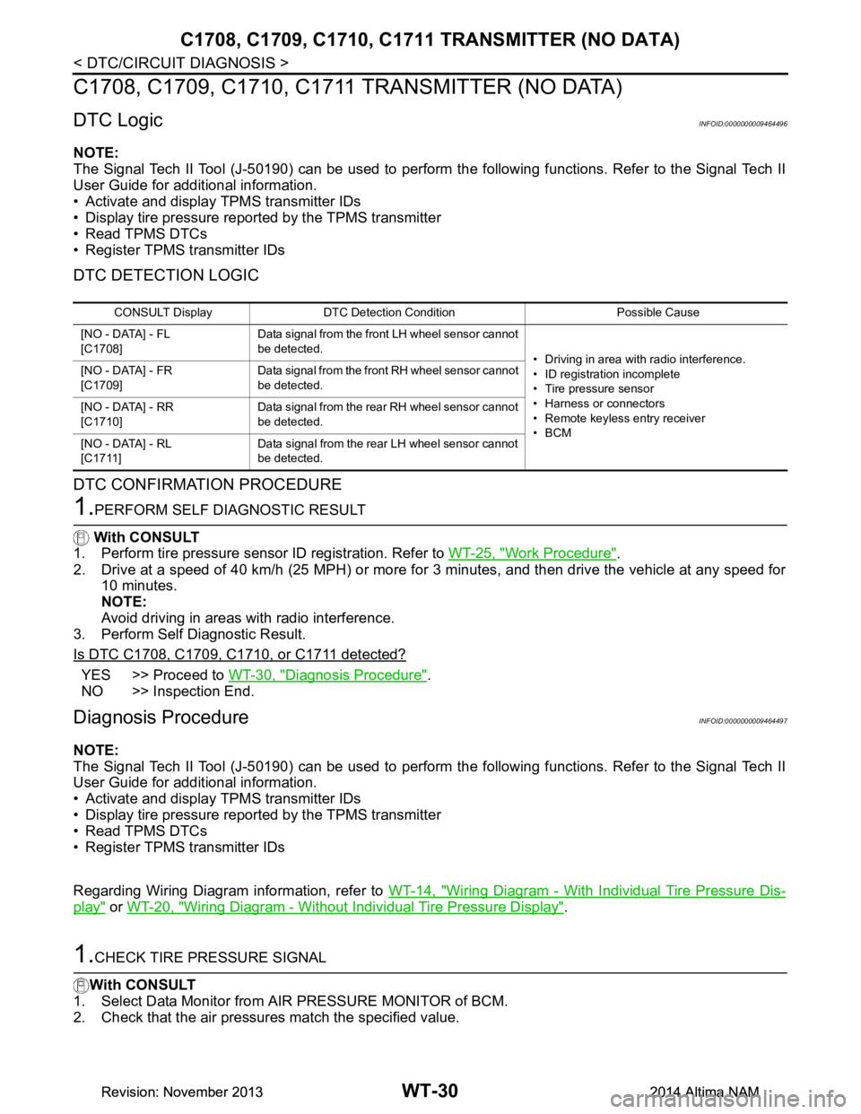
C1708, C1709, C1710, C1711 TRANSMITTER (NO DATA)
C1708, C1709, C1710, C1711 TRANSMITTER (NO DATA)
DTC LogicINFOID:0000000009464496
NOTE:
The Signal Tech II Tool (J-50190) can be used to perform the following functions. Refer to the Signal Tech II
User Guide for additional information.
• Activate and display TPMS transmitter IDs
• Display tire pressure reported by the TPMS transmitter
• Read TPMS DTCs
• Register TPMS transmitter IDs
DTC DETECTION LOGIC
DTC CONFIRMATION PROCEDURE
1.PERFORM SELF DIAGNOSTIC RESULT
With CONSULT
1. Perform tire pressure sensor ID registration. Refer to WT-25, "Work Procedure"
.
2. Drive at a speed of 40 km/h (25 MPH) or more fo r 3 minutes, and then drive the vehicle at any speed for
10 minutes.
NOTE:
Avoid driving in areas with radio interference.
3. Perform Self Diagnostic Result.
Is DTC C1708, C1709, C1710, or C1711 detected?
YES >> Proceed to WT-30, "Diagnosis Procedure".
NO >> Inspection End.
Diagnosis ProcedureINFOID:0000000009464497
NOTE:
The Signal Tech II Tool (J-50190) can be used to perform the following functions. Refer to the Signal Tech II
User Guide for additional information.
• Activate and display TPMS transmitter IDs
• Display tire pressure reported by the TPMS transmitter
• Read TPMS DTCs
• Register TPMS transmitter IDs
Regarding Wiring Diagram information, refer to WT-14, "Wiring Diagram - With Individual Tire Pressure Dis-
play" or WT-20, "Wiring Diagram - Without Individual Tire Pressure Display".
1.CHECK TIRE PRESSURE SIGNAL
With CONSULT
1. Select Data Monitor from AIR PRESSURE MONITOR of BCM.
2. Check that the air pressures match the specified value.
CONSULT Display DTC Detectio n Condition Possible Cause
[NO - DATA] - FL
[C1708] Data signal from the front LH wheel sensor cannot
be detected. • Driving in area with radio interference.
• ID registration incomplete
• Tire pressure sensor
• Harness or connectors
• Remote keyless entry receiver
•BCM
[NO - DATA] - FR
[C1709] Data signal from the front RH wheel sensor cannot
be detected.
[NO - DATA] - RR
[C1710] Data signal from the rear RH wheel sensor cannot
be detected.
[NO - DATA] - RL
[C1711] Data signal from the rear LH wheel sensor cannot
be detected.
Revision: November 20132014 Altima NAMRevision: November 20132014 Altima NAM