2014 NISSAN TEANA ignition
[x] Cancel search: ignitionPage 2839 of 4801
INL-18
< SYSTEM DESCRIPTION >
DIAGNOSIS SYSTEM (IPDM E/R)
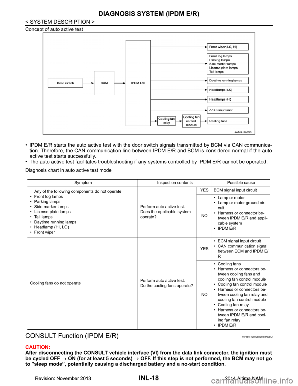
Concept of auto active test
• IPDM E/R starts the auto active test with the door switch signals transmitted by BCM via CAN communica-
tion. Therefore, the CAN communication line between IPDM E/R and BCM is considered normal if the auto
active test starts successfully.
• The auto active test facilitates troubleshooting if any systems controlled by IPDM E/R cannot be operated.
Diagnosis chart in auto active test mode
CONSULT Function (IPDM E/R)INFOID:0000000009956804
CAUTION:
After disconnecting the CONSULT vehicle interface (VI) from the data link connector, the ignition must
be cycled OFF → ON (for at least 5 seconds) → OFF. If this step is not performed, the BCM may not go
to ”sleep mode”, potentially causing a di scharged battery and a no-start condition.
AWMIA1280GB
Symptom Inspection contents Possible cause
Any of the following components do not operate
•Front fog lamps
• Parking lamps
• Side marker lamps
• License plate lamps
•Tail lamps
• Daytime running lamps
• Headlamp (HI, LO)
• Front wiper Perform auto active test.
Does the applicable system
operate? YES BCM signal input circuit
NO • Lamp or motor
• Lamp or motor ground cir-
cuit
• Harness or connector be- tween IPDM E/R and appli-
cable system
•IPDM E/R
Cooling fans do not operate Perform auto active test.
Do the cooling fans operate? YES
• ECM signal input circuit
• CAN communication signal between ECM and IPDM E/
R
NO • Cooling fans
• Harness or connectors be-
tween cooling fans and
cooling fan control module
• Cooling fan control module
• Harness or connectors be- tween cooling fan relay and
cooling fan control module
• Cooling fan relay
• Harness or connectors be- tween IPDM E/R and cool-
ing fan relay
•IPDM E/R
Revision: November 20132014 Altima NAMRevision: November 20132014 Altima NAM
Page 2840 of 4801
DIAGNOSIS SYSTEM (IPDM E/R)INL-19
< SYSTEM DESCRIPTION >
C
D E
F
G H
I
J
K
M A
B
INL
N
O P
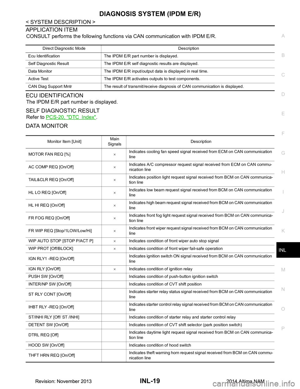
APPLICATION ITEM
CONSULT performs the following functions via CAN communication with IPDM E/R.
ECU IDENTIFICATION
The IPDM E/R part number is displayed.
SELF DIAGNOSTIC RESULT
Refer to PCS-20, "DTC Index".
DATA MONITOR
Direct Diagnostic Mode Description
Ecu Identification The IPDM E/R part number is displayed.
Self Diagnostic Result The IPDM E/R self diagnostic results are displayed.
Data Monitor The IPDM E/R input/output data is displayed in real time.
Active Test The IPDM E/R activates outputs to test components.
CAN Diag Support Mntr The result of transmit/receive diagnosis of CAN communication is displayed.
Monitor Item [Unit] Main
Signals Description
MOTOR FAN REQ [%] ×Indicates cooling fan speed signal received from ECM on CAN communication
line
AC COMP REQ [On/Off] ×Indicates A/C compressor request signal received from ECM on CAN commu-
nication line
TAIL&CLR REQ [On/Off] ×Indicates position light request signal
received from BCM on CAN communica-
tion line
HL LO REQ [On/Off] ×Indicates low beam request signal received from BCM on CAN communication
line
HL HI REQ [On/Off] ×Indicates high beam request signal received from BCM on CAN communication
line
FR FOG REQ [On/Off] ×Indicates front fog light request signal received from BCM on CAN communica-
tion line
FR WIP REQ [Stop/1LOW/Low/Hi] ×Indicates front wiper request signal received from BCM on CAN communication
line
WIP AUTO STOP [STOP P/ACT P] ×Indicates condition of front wiper auto stop signal
WIP PROT [Off/BLOCK] ×Indicates condition of front wiper fail-safe operation
IGN RLY1 -REQ [On/Off] Indicates ignition switch ON signal received from BCM on CAN communication
line
IGN RLY [On/Off] ×Indicates condition of ignition relay
PUSH SW [On/Off] Indicates condition of push-button ignition switch
INTER/NP SW [On/Off] Indicates condition of CVT shift position
ST RLY CONT [On/Off] Indicates starter relay status signal received from BCM on CAN communication
line
IHBT RLY -REQ [On/Off] Indicates starter control relay signal received from BCM on CAN communication
line
ST/INHI RLY [Off/ ST /INHI] Indicates condition of starter relay and starter control relay
DETENT SW [On/Off] Indicates condition of CVT shift selector (park position switch)
DTRL REQ [Off] Indicates daytime light request signal received from BCM on CAN communica-
tion line
HOOD SW [On/Off] Indicates condition of hood switch
THFT HRN REQ [On/Off] Indicates theft warning horn request signal received from BCM on CAN commu-
nication line
Revision: November 20132014 Altima NAMRevision: November 20132014 Altima NAM
Page 2872 of 4801
POWER SUPPLY AND GROUND CIRCUITINL-51
< DTC/CIRCUIT DIAGNOSIS >
C
D E
F
G H
I
J
K
M A
B
INL
N
O P
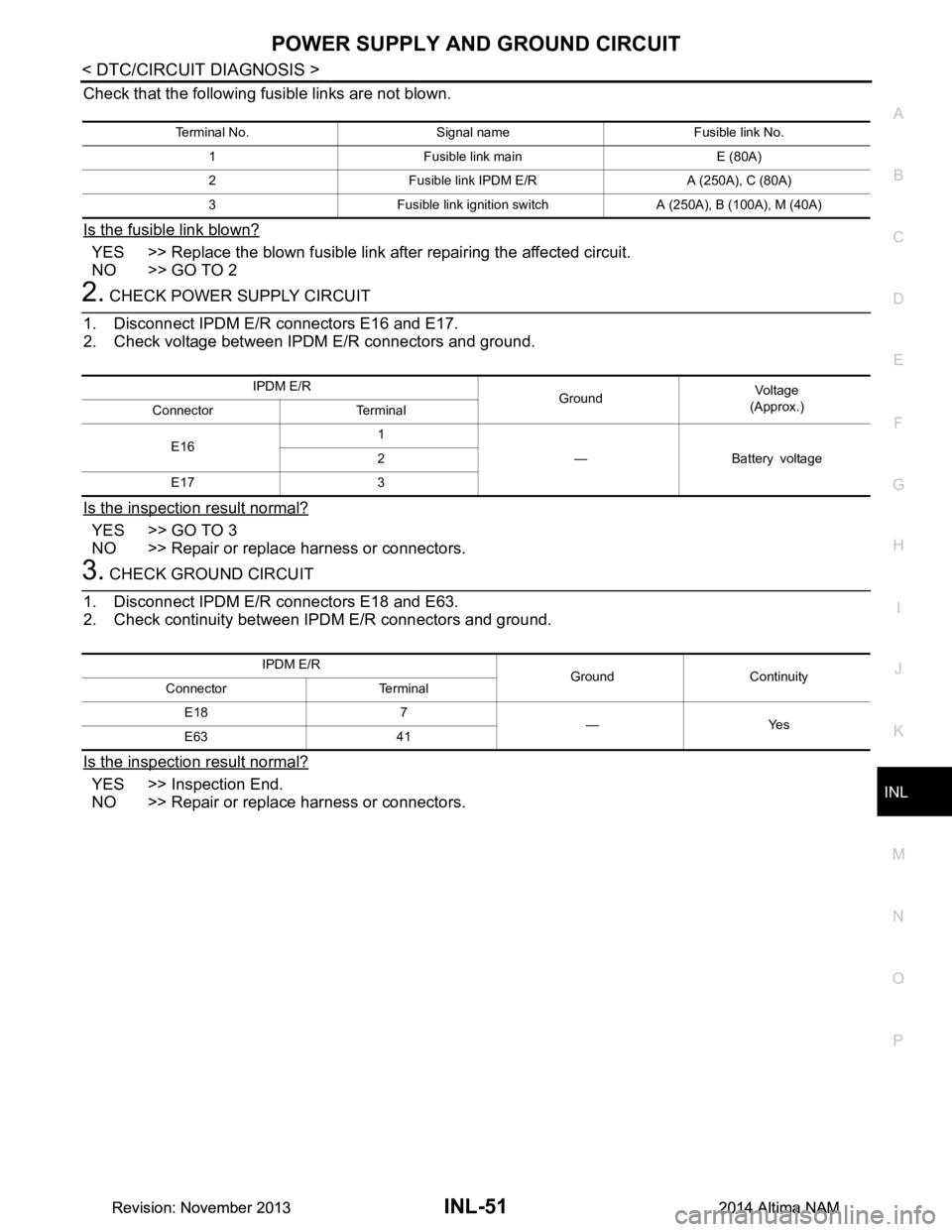
Check that the following fusible links are not blown.
Is the fusible link blown?
YES >> Replace the blown fusible link after repairing the affected circuit.
NO >> GO TO 2
2. CHECK POWER SUPPLY CIRCUIT
1. Disconnect IPDM E/R connectors E16 and E17.
2. Check voltage between IPDM E/R connectors and ground.
Is the inspection result normal?
YES >> GO TO 3
NO >> Repair or replace harness or connectors.
3. CHECK GROUND CIRCUIT
1. Disconnect IPDM E/R connectors E18 and E63.
2. Check continuity between IPDM E/R connectors and ground.
Is the inspection result normal?
YES >> Inspection End.
NO >> Repair or replace harness or connectors.
Terminal No. Signal name Fusible link No.
1 Fusible link main E (80A)
2 Fusible link IPDM E/R A (250A), C (80A)
3 Fusible link ignition switch A (250A), B (100A), M (40A)
IPDM E/R GroundVol tag e
(Approx.)
Connector Terminal
E16 1
— Battery voltage
2
E17 3
IPDM E/R Ground Continuity
Connector Terminal
E18 7 —Yes
E63 41
Revision: November 20132014 Altima NAMRevision: November 20132014 Altima NAM
Page 2873 of 4801
INL-52
< DTC/CIRCUIT DIAGNOSIS >
BATTERY SAVER OUTPUT/POWER SUPPLY CIRCUIT
BATTERY SAVER OUTPUT/POWER SUPPLY CIRCUIT
DescriptionINFOID:0000000009463879
Provides the interior room lamp power supply. Also cuts the power supply when the interior room lamp battery
saver is activating.
Component Function CheckINFOID:0000000009463880
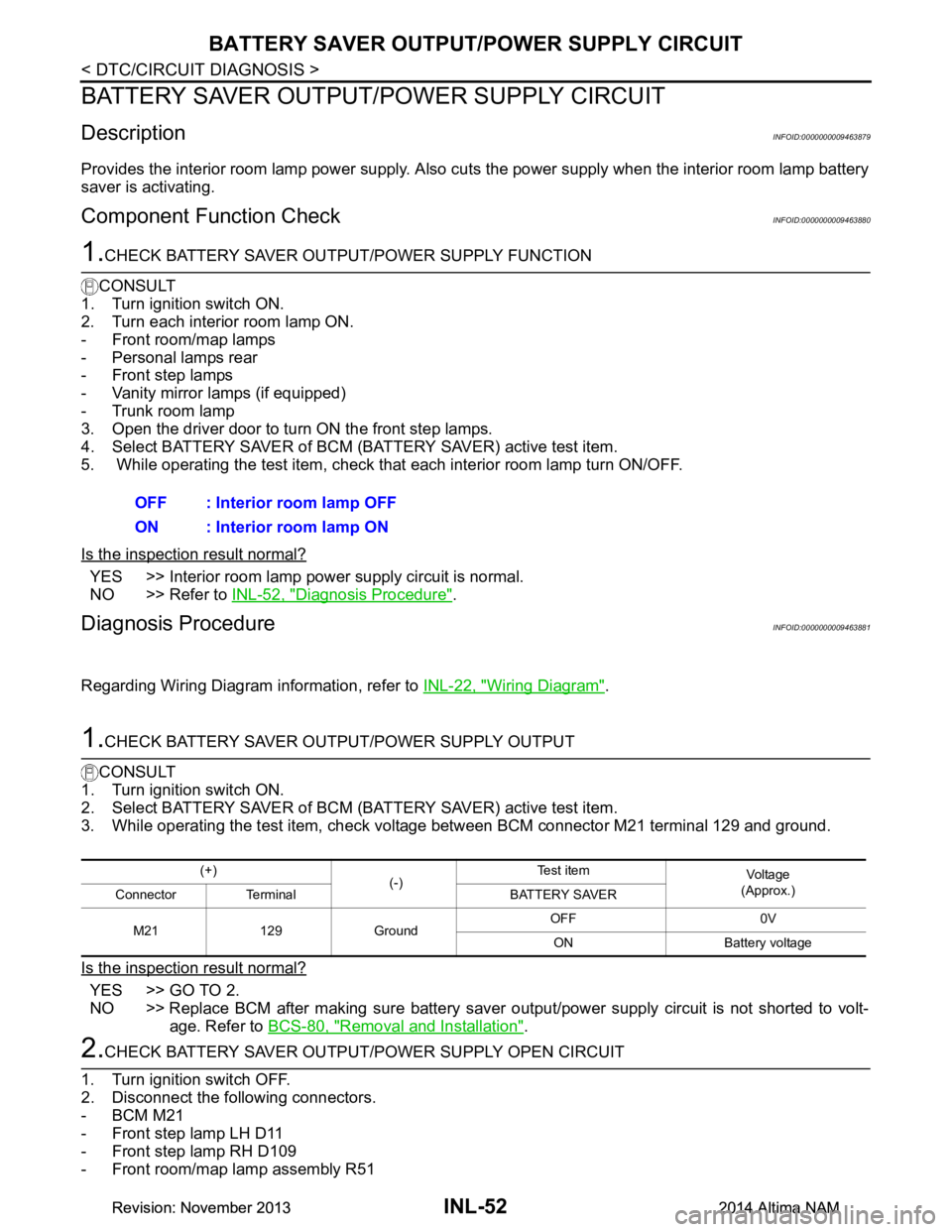
1.CHECK BATTERY SAVER OUTPUT /POWER SUPPLY FUNCTION
CONSULT
1. Turn ignition switch ON.
2. Turn each interior room lamp ON.
- Front room/map lamps
- Personal lamps rear
- Front step lamps
- Vanity mirror lamps (if equipped)
- Trunk room lamp
3. Open the driver door to turn ON the front step lamps.
4. Select BATTERY SAVER of BCM (BATTERY SAVER) active test item.
5. While operating the test item, check that each interior room lamp turn ON/OFF.
Is the inspection result normal?
YES >> Interior room lamp power supply circuit is normal.
NO >> Refer to INL-52, "Diagnosis Procedure"
.
Diagnosis ProcedureINFOID:0000000009463881
Regarding Wiring Diagram information, refer to INL-22, "Wiring Diagram".
1.CHECK BATTERY SAVER OUTPUT/POWER SUPPLY OUTPUT
CONSULT
1. Turn ignition switch ON.
2. Select BATTERY SAVER of BCM (BATTERY SAVER) active test item.
3. While operating the test item, check voltage between BCM connector M21 terminal 129 and ground.
Is the inspection result normal?
YES >> GO TO 2.
NO >> Replace BCM after making sure battery saver out put/power supply circuit is not shorted to volt-
age. Refer to BCS-80, "Removal and Installation"
.
2.CHECK BATTERY SAVER OUTPUT/P OWER SUPPLY OPEN CIRCUIT
1. Turn ignition switch OFF.
2. Disconnect the following connectors.
-BCM M21
- Front step lamp LH D11
- Front step lamp RH D109
- Front room/map lamp assembly R51 OFF : Interior room lamp OFF
ON : Interior room lamp ON
(+) (-)Te s t i t e m
Vo l ta g e
(Approx.)
Connector Terminal BATTERY SAVER
M21 129 Ground OFF 0V
ON Battery voltage
Revision: November 20132014 Altima NAMRevision: November 20132014 Altima NAM
Page 2875 of 4801
INL-54
< DTC/CIRCUIT DIAGNOSIS >
INTERIOR ROOM LAMP CONTROL CIRCUIT
INTERIOR ROOM LAMP CONTROL CIRCUIT
DescriptionINFOID:0000000009463882
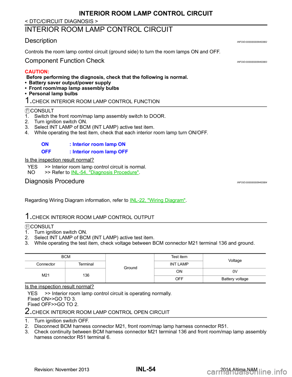
Controls the room lamp control circuit (ground side) to turn the room lamps ON and OFF.
Component Function CheckINFOID:0000000009463883
CAUTION:
Before performing the diagnosis, check that the following is normal.
• Battery saver output/power supply
• Front room/map lamp assembly bulbs
• Personal lamp bulbs
1.CHECK INTERIOR ROOM LAMP CONTROL FUNCTION
CONSULT
1. Switch the front room/map lamp assembly switch to DOOR.
2. Turn ignition switch ON.
3. Select INT LAMP of BCM (INT LAMP) active test item.
4. While operating the test item, check that each interior room lamp turn ON/OFF.
Is the inspection result normal?
YES >> Interior room lamp control circuit is normal.
NO >> Refer to INL-54, "Diagnosis Procedure"
.
Diagnosis ProcedureINFOID:0000000009463884
Regarding Wiring Diagram information, refer to INL-22, "Wiring Diagram".
1.CHECK INTERIOR ROOM LAMP CONTROL OUTPUT
CONSULT
1. Turn ignition switch ON.
2. Select INT LAMP of BCM (INT LAMP) active test item.
3. While operating the test item, check voltage between BCM connector M21 terminal 136 and ground.
Is the inspection result normal?
YES >> Interior room lamp control circuit is operating normally.
Fixed ON>>GO TO 3.
Fixed OFF>>GO TO 2.
2.CHECK INTERIOR ROOM LA MP CONTROL OPEN CIRCUIT
1. Turn ignition switch OFF.
2. Disconnect BCM harness connector M21, front room/map lamp harness connector R51.
3. Check continuity between BCM harness connector M21 terminal 136 and front room/map lamp assembly
harness connector R51 terminal 6.ON : Interior room lamp ON
OFF : Interior room lamp OFF
BCM
GroundTe s t i t e m
Voltag e
Connector Terminal INT LAMP
M21 136 ON 0V
OFF Battery voltage
Revision: November 20132014 Altima NAMRevision: November 20132014 Altima NAM
Page 2876 of 4801
INTERIOR ROOM LAMP CONTROL CIRCUITINL-55
< DTC/CIRCUIT DIAGNOSIS >
C
D E
F
G H
I
J
K
M A
B
INL
N
O P
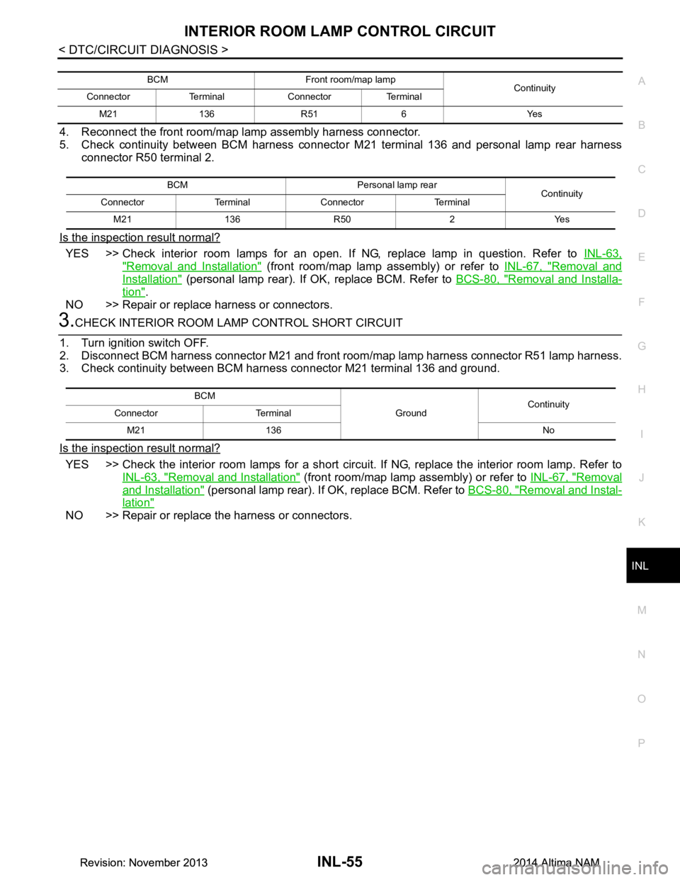
4. Reconnect the front room/map lamp assembly harness connector.
5. Check continuity between BCM harness connector M21 terminal 136 and personal lamp rear harness
connector R50 terminal 2.
Is the inspection result normal?
YES >> Check interior room lamps for an open. If NG, replace lamp in question. Refer to INL-63,
"Removal and Installation" (front room/map lamp assembly) or refer to INL-67, "Removal and
Installation" (personal lamp rear). If OK, replace BCM. Refer to BCS-80, "Removal and Installa-
tion".
NO >> Repair or replace harness or connectors.
3.CHECK INTERIOR ROOM LAMP CONTROL SHORT CIRCUIT
1. Turn ignition switch OFF.
2. Disconnect BCM harness connector M21 and front room/map lamp harness connector R51 lamp harness.
3. Check continuity between BCM harness connector M21 terminal 136 and ground.
Is the inspection result normal?
YES >> Check the interior room lamps for a short circui t. If NG, replace the interior room lamp. Refer to
INL-63, "Removal and Installation"
(front room/map lamp assembly) or refer to INL-67, "Removal
and Installation" (personal lamp rear). If OK, replace BCM. Refer to BCS-80, "Removal and Instal-
lation"
NO >> Repair or replace the harness or connectors.
BCM Front room/map lamp
Continuity
Connector Terminal Connector Terminal
M21 136 R51 6 Yes
BCM Personal lamp rear Continuity
Connector Terminal Connector Terminal
M21 136 R50 2 Yes
BCM GroundContinuity
Connector Terminal
M21 136 No
Revision: November 20132014 Altima NAMRevision: November 20132014 Altima NAM
Page 2877 of 4801
INL-56
< DTC/CIRCUIT DIAGNOSIS >
STEP LAMP CIRCUIT
STEP LAMP CIRCUIT
DescriptionINFOID:0000000009463885
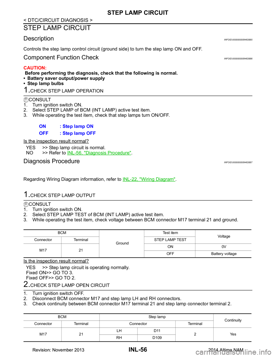
Controls the step lamp control circuit (ground side) to turn the step lamp ON and OFF.
Component Function CheckINFOID:0000000009463886
CAUTION:
Before performing the diagnosis, check that the following is normal.
• Battery saver output/power supply
• Step lamp bulbs
1.CHECK STEP LAMP OPERATION
CONSULT
1. Turn ignition switch ON.
2. Select STEP LAMP of BCM (I NT LAMP) active test item.
3. While operating the test item, c heck that step lamps turn ON/OFF.
Is the inspection result normal?
YES >> Step lamp circuit is normal.
NO >> Refer to INL-56, "Diagnosis Procedure"
.
Diagnosis ProcedureINFOID:0000000009463887
Regarding Wiring Diagram information, refer to INL-22, "Wiring Diagram".
1.CHECK STEP LAMP OUTPUT
CONSULT
1. Turn ignition switch ON.
2. Select STEP LAMP TEST of BC M (INT LAMP) active test item.
3. While operating the test item, check voltage between BCM connector M17 terminal 21 and ground.
Is the inspection result normal?
YES >> Step lamp circuit is operating normally.
Fixed ON>> GO TO 3.
Fixed OFF>> GO TO 2.
2.CHECK STEP LAMP OPEN CIRCUIT
1. Turn ignition switch OFF.
2. Disconnect BCM connector M17 and step lamp LH and RH connectors.
3. Check continuity between BCM connector M17 terminal 21 and step lamp connector terminal 2.
ON : Step lamp ON
OFF : Step lamp OFF
BCM
GroundTe s t i t e m
Vo l ta g e
Connector Terminal STEP LAMP TEST
M17 21 ON 0V
OFF Battery voltage
BCM Step lamp Continuity
Connector Terminal Connector Terminal
M17 21 LH D11
2Yes
RH D109
Revision: November 20132014 Altima NAMRevision: November 20132014 Altima NAM
Page 2878 of 4801
STEP LAMP CIRCUITINL-57
< DTC/CIRCUIT DIAGNOSIS >
C
D E
F
G H
I
J
K
M A
B
INL
N
O P
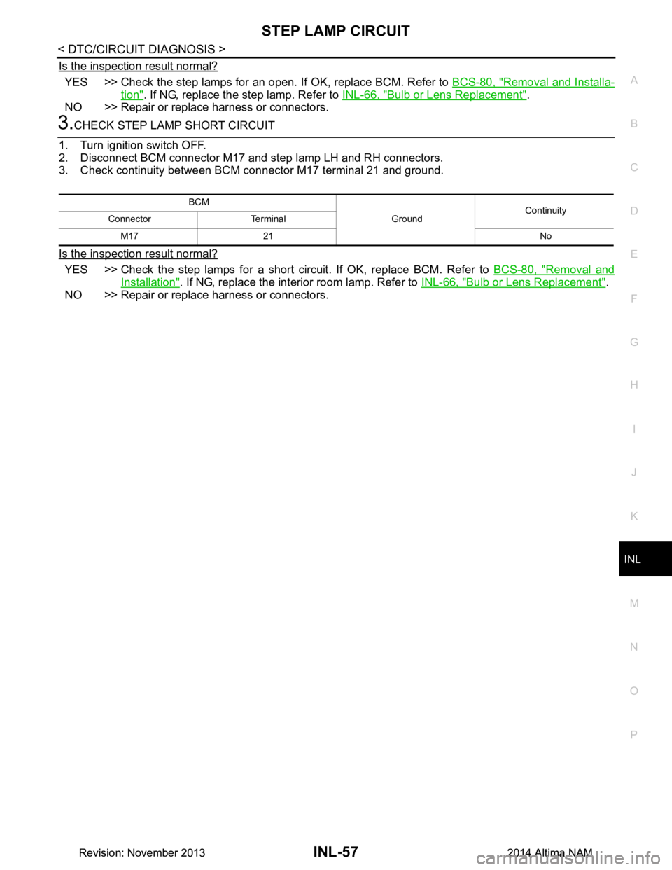
Is the inspection result normal?
YES >> Check the step lamps for an open. If OK, replace BCM. Refer to BCS-80, "Removal and Installa-
tion". If NG, replace the step lamp. Refer to INL-66, "Bulb or Lens Replacement".
NO >> Repair or replace harness or connectors.
3.CHECK STEP LAMP SHORT CIRCUIT
1. Turn ignition switch OFF.
2. Disconnect BCM connector M17 and step lamp LH and RH connectors.
3. Check continuity between BCM connector M17 terminal 21 and ground.
Is the inspection result normal?
YES >> Check the step lamps for a short circuit. If OK, replace BCM. Refer to BCS-80, "Removal and
Installation". If NG, replace the interior room lamp. Refer to INL-66, "Bulb or Lens Replacement".
NO >> Repair or replace harness or connectors.
BCM
GroundContinuity
Connector Terminal
M17 21 No
Revision: November 20132014 Altima NAMRevision: November 20132014 Altima NAM