2014 NISSAN QUEST warning
[x] Cancel search: warningPage 174 of 482
.Never pour fuel into the throttle
body to attempt to start your vehi-
cle.
. Close the sliding door before open-
ing the fuel-filler door.
. Do not fill a portable fuel container
in the vehicle or trailer. Static elec-
tricity can cause an explosion of
flammable liquid, vapor or gas in
any vehicle or trailer. To reduce the
risk of serious injury or death when
filling portable fuel containers:
— Always place the container on
the ground when filling.
— Do not use electronic devices when filling.
— Keep the pump nozzle in contact with the container while you are
filling it.
— Use only approved portable fuel containers for flammable liquid.
CAUTION
. If fuel is spilled on the vehicle body,
flush it away with water to avoid paint damage.
. Insert the cap straight into the fuel-
filler tube, then tighten until the
fuel-filler cap clicks. Failure to tight-
en the fuel-filler cap properly may
cause the
malfunction indicator
light (MIL) to illuminate. If the
light illuminates because the fuel-
filler cap is loose or missing, tighten
or install the cap and continue to
drive the vehicle. The
light
should turn off after a few driving
trips. If the
light does not turn
off after a few driving trips, have the
vehicle inspected by a NISSAN deal-
er.
For additional information, see
“Malfunction Indicator Light (MIL)”
(P.2-17) .
. The LOOSE FUEL CAP warning will
appear if the fuel-filler cap is not
properly tightened. It may take a few
driving trips for the message to be
displayed. Failure to tighten the
fuel-filler cap properly after the
LOOSE FUEL CAP warning appears
may cause the
Malfunction
Indicator Light (MIL) to illuminate.
JVP0067X
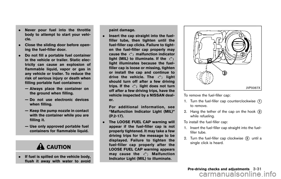
To remove the fuel-filler cap:
1. Turn the fuel-filler cap counterclockwise
*1to remove.
2. Hang the tether of the cap on the hook
*3while refueling.
To install the fuel-filler cap:
1. Insert the fuel-filler cap straight into the fuel- filler tube.
2. Turn the fuel-filler cap clockwise
*2until a
single click is heard.
Pre-driving checks and adjustments3-31
Page 175 of 482
3-32Pre-driving checks and adjustments
SPA2833
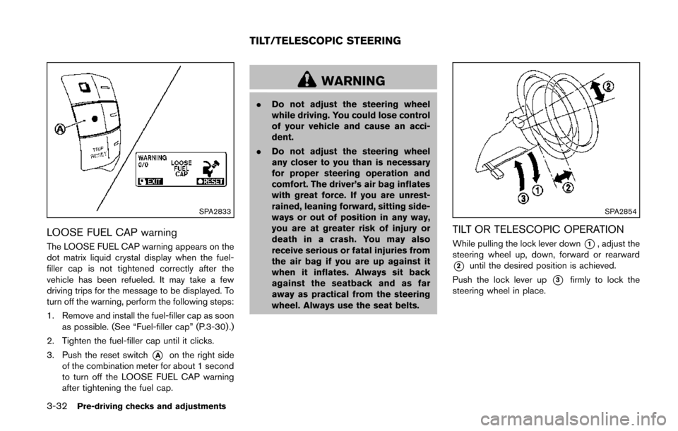
LOOSE FUEL CAP warning
The LOOSE FUEL CAP warning appears on the
dot matrix liquid crystal display when the fuel-
filler cap is not tightened correctly after the
vehicle has been refueled. It may take a few
driving trips for the message to be displayed. To
turn off the warning, perform the following steps:
1. Remove and install the fuel-filler cap as soonas possible. (See “Fuel-filler cap” (P.3-30) .)
2. Tighten the fuel-filler cap until it clicks.
3. Push the reset switch
*Aon the right side
of the combination meter for about 1 second
to turn off the LOOSE FUEL CAP warning
after tightening the fuel cap.
WARNING
. Do not adjust the steering wheel
while driving. You could lose control
of your vehicle and cause an acci-
dent.
. Do not adjust the steering wheel
any closer to you than is necessary
for proper steering operation and
comfort. The driver’s air bag inflates
with great force. If you are unrest-
rained, leaning forward, sitting side-
ways or out of position in any way,
you are at greater risk of injury or
death in a crash. You may also
receive serious or fatal injuries from
the air bag if you are up against it
when it inflates. Always sit back
against the seatback and as far
away as practical from the steering
wheel. Always use the seat belts.
SPA2854
TILT OR TELESCOPIC OPERATION
While pulling the lock lever down*1, adjust the
steering wheel up, down, forward or rearward
*2until the desired position is achieved.
Push the lock lever up
*3firmly to lock the
steering wheel in place.
TILT/TELESCOPIC STEERING
Page 177 of 482
3-34Pre-driving checks and adjustments
SPA2143
Manual anti-glare type
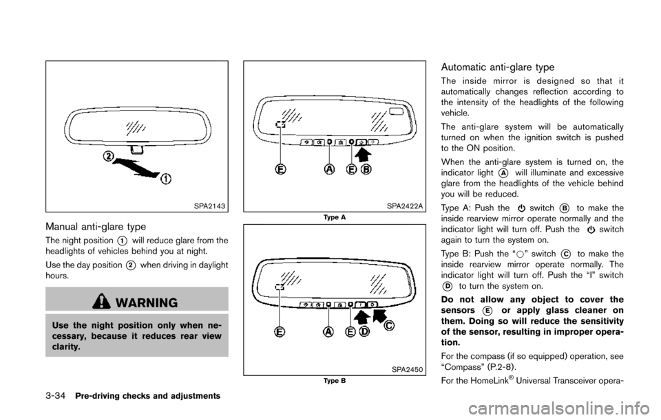
The night position*1will reduce glare from the
headlights of vehicles behind you at night.
Use the day position
*2when driving in daylight
hours.
WARNING
Use the night position only when ne-
cessary, because it reduces rear view
clarity.
SPA2422AType A
SPA2450Type B
Automatic anti-glare type
The inside mirror is designed so that it
automatically changes reflection according to
the intensity of the headlights of the following
vehicle.
The anti-glare system will be automatically
turned on when the ignition switch is pushed
to the ON position.
When the anti-glare system is turned on, the
indicator light
*Awill illuminate and excessive
glare from the headlights of the vehicle behind
you will be reduced.
Type A: Push the
switch*Bto make the
inside rearview mirror operate normally and the
indicator light will turn off. Push the
switch
again to turn the system on.
Type B: Push the “*” switch
*Cto make the
inside rearview mirror operate normally. The
indicator light will turn off. Push the “I” switch
*Dto turn the system on.
Do not allow any object to cover the
sensors
*Eor apply glass cleaner on
them. Doing so will reduce the sensitivity
of the sensor, resulting in improper opera-
tion.
For the compass (if so equipped) operation, see
“Compass” (P.2-8) .
For the HomeLink
®Universal Transceiver opera-
Page 178 of 482
tion, see “HomeLink®Universal Transceiver”
(P.2-59) .
OUTSIDE MIRRORS
WARNING
Objects viewed in the outside mirror on
the passenger side are closer than they
appear. Be careful when moving to the
right. Using only this mirror could cause
an accident. Use the inside mirror or
glance over your shoulder to properly
judge distances to other objects.
SPA2319
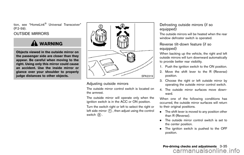
Adjusting outside mirrors
The outside mirror control switch is located on
the armrest.
The outside mirror will operate only when the
ignition switch is in the ACC or ON position.
Turn the switch right or left to select the right or
left side mirror
*1, then adjust using the control
switch
*2.
Defrosting outside mirrors (if so
equipped)
The outside mirrors will be heated when the rear
window defroster switch is operated.
Reverse tilt-down feature (if so
equipped)
When backing up the vehicle, the right and left
outside mirrors will turn downward automatically
to provide better rear visibility.
1. Push the ignition switch to the ON position.
2. Move the shift lever to the R (Reverse) position.
3. Choose the right or left outside mirror by operating the outside mirror control switch.
4. The outside mirror surfaces move down- ward.
When one of the following conditions has
occurred, the outside mirror surfaces will return
to their original positions.
. The shift lever is moved to any position other
than R (Reverse).
. The outside mirror control switch is set to
the center position.
. The ignition switch is pushed to the OFF
position.
Pre-driving checks and adjustments3-35
Page 186 of 482
WARNING
.Do not disassemble or modify this
system. If you do, it may result in
accidents, fire, or electric shock.
. Do not use this system if you notice
any abnormality, such as a frozen
screen or lack of sound. Continued
use of the system may result in
accident, fire or electric shock.
. In case you notice any foreign
object in the system hardware, spill
liquid on it, or notice smoke or smell
coming from it, stop using the
system immediately and contact
your nearest NISSAN dealer. Ignor-
ing such conditions may lead to
accidents, fire, or electric shock.
. Park the vehicle in a safe location
and apply the parking brake to view
the images on the front center dis-
play screen.
Do not attempt to operate the system in
extreme temperature conditions [below
− 48F( −208 C) and above 1588 F (708C)].
Operating this system under these condi-
tions may result in system malfunctions.
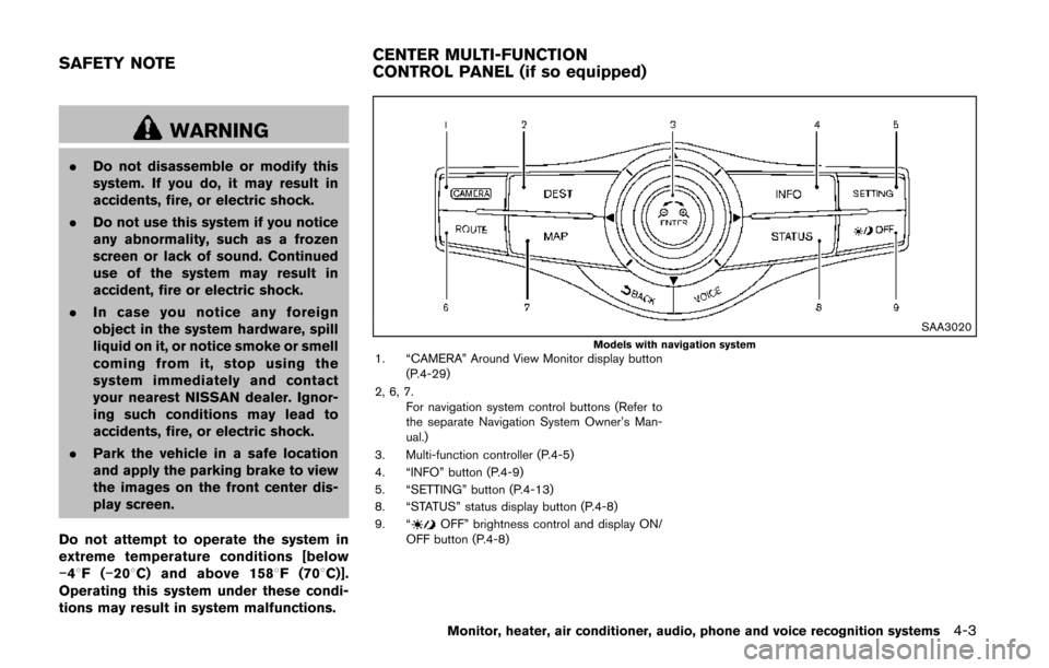
SAA3020Models with navigation system1. “CAMERA” Around View Monitor display button (P.4-29)
2, 6, 7. For navigation system control buttons (Refer to
the separate Navigation System Owner’s Man-
ual.)
3. Multi-function controller (P.4-5)
4. “INFO” button (P.4-9)
5. “SETTING” button (P.4-13)
8. “STATUS” status display button (P.4-8)
9. “
OFF” brightness control and display ON/
OFF button (P.4-8)
Monitor, heater, air conditioner, audio, phone and voice recognition systems4-3
SAFETY NOTE CENTER MULTI-FUNCTION
CONTROL PANEL (if so equipped)
Page 188 of 482
HOW TO USE MULTI-FUNCTION
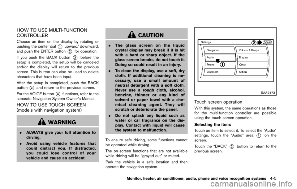
CONTROLLER
Choose an item on the display by rotating or
pushing the center dial
*1upward/ downward,
and push the ENTER button
*2for operation.
If you push the BACK button
*3before the
setup is completed, the setup will be canceled
and/or the display will return to the previous
screen. This button can also be used to delete
characters that have been input.
After the setup is completed, push the BACK
button
*3and return to the previous screen.
For the VOICE button
*4functions, refer to the
separate Navigation System Owner’s Manual.
HOW TO USE TOUCH SCREEN
(models with navigation system)
WARNING
. ALWAYS give your full attention to
driving.
. Avoid using vehicle features that
could distract you. If distracted,
you could lose control of your
vehicle and cause an accident.
CAUTION
.The glass screen on the liquid
crystal display may break if it is hit
with a hard or sharp object. If the
glass screen breaks, do not touch it.
Doing so could result in an injury.
. To clean the display, use a soft, dry
cloth. If additional cleaning is ne-
cessary, use a small amount of
neutral detergent with a soft cloth.
Never use a rough cloth, alcohol,
benzine, thinner or any kind of
solvent or paper towel with a che-
mical cleaning agent. They will
scratch or deteriorate the panel.
. Do not splash any liquid such as
water or car fragrance on the dis-
play. Contact with liquid will cause
the system to malfunction.
To ensure safe driving, some functions cannot
be operated while driving.
The on-screen functions that are not available
while driving will be “grayed out” or muted.
Park the vehicle in a safe location and then
operate the navigation system.
SAA2473
Touch screen operation
With this system, the same operations as those
for the multi-function controller are possible
using the touch screen operation.
Selecting the item:
Touch an item to select it. To select the “Audio”
settings, touch the “Audio” area
*1on the
screen.
Touch the “BACK”
*2button to return to the
previous screen.
Monitor, heater, air conditioner, audio, phone and voice recognition systems4-5
Page 206 of 482
The system is designed as an aid to the driver in
situations such as slot parking or parallel
parking.
When the shift lever is shifted into the R
(Reverse) position, the monitor display shows
the view to the rear of the vehicle.
WARNING
.The RearView Monitor is a conve-
nience but it is not a substitute to
check behind the vehicle when
backing up.
. The driver is always responsible for
safety during parking and other
maneuvers.
. Objects viewed in the RearView
Monitor differ from actual distance
because a wide-angle lens is used.
Objects in the RearView Monitor
will appear visually opposite like
ones viewed in the inside and out-
side mirrors.
. Make sure that the lift gate is
securely closed when backing up.
. Underneath the bumper and the
corner areas of the bumper cannot
be viewed on the RearView Monitor because of its monitoring range
limitation.
. Do not put anything on the Rear-
View camera. The RearView camera
is installed above the license plate.
. When washing the vehicle with
high-pressure water, be sure not to
spray it around the camera. Other-
wise, water may enter the camera
unit causing water condensation on
the lens, a malfunction, fire or an
electric shock.
. Do not strike the camera. It is a
precision instrument. Otherwise, it
may malfunction or cause damage
resulting in a fire or an electric
shock.
CAUTION
Do not scratch the camera lens when
cleaning dirt or snow from the lens.
SAA1896
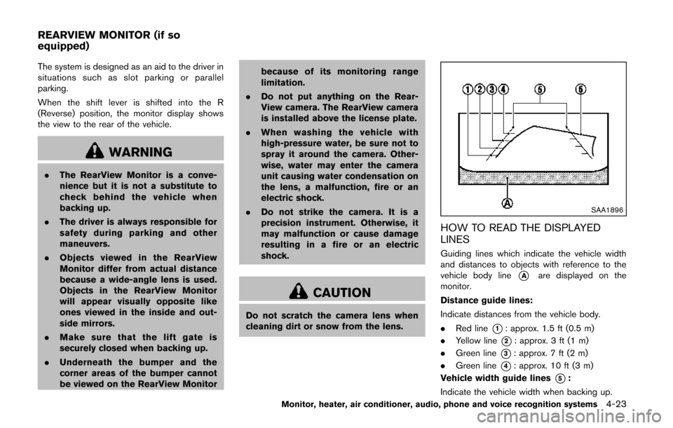
HOW TO READ THE DISPLAYED
LINES
Guiding lines which indicate the vehicle width
and distances to objects with reference to the
vehicle body line
*Aare displayed on the
monitor.
Distance guide lines:
Indicate distances from the vehicle body.
. Red line
*1: approx. 1.5 ft (0.5 m)
. Yellow line
*2: approx. 3 ft (1 m)
. Green line
*3: approx. 7 ft (2 m)
. Green line
*4: approx. 10 ft (3 m)
Vehicle width guide lines
*5:
Indicate the vehicle width when backing up.
Monitor, heater, air conditioner, audio, phone and voice recognition systems4-23
REARVIEW MONITOR (if so
equipped)
Page 207 of 482
4-24Monitor, heater, air conditioner, audio, phone and voice recognition systems
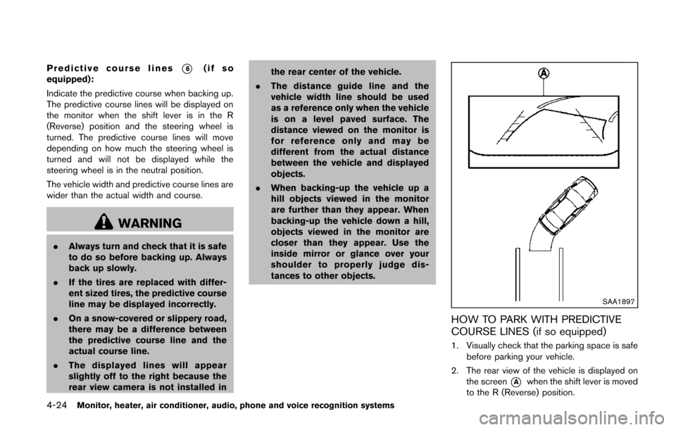
Predictive course lines*6(if so
equipped):
Indicate the predictive course when backing up.
The predictive course lines will be displayed on
the monitor when the shift lever is in the R
(Reverse) position and the steering wheel is
turned. The predictive course lines will move
depending on how much the steering wheel is
turned and will not be displayed while the
steering wheel is in the neutral position.
The vehicle width and predictive course lines are
wider than the actual width and course.
WARNING
. Always turn and check that it is safe
to do so before backing up. Always
back up slowly.
. If the tires are replaced with differ-
ent sized tires, the predictive course
line may be displayed incorrectly.
. On a snow-covered or slippery road,
there may be a difference between
the predictive course line and the
actual course line.
. The displayed lines will appear
slightly off to the right because the
rear view camera is not installed in the rear center of the vehicle.
. The distance guide line and the
vehicle width line should be used
as a reference only when the vehicle
is on a level paved surface. The
distance viewed on the monitor is
for reference only and may be
different from the actual distance
between the vehicle and displayed
objects.
. When backing-up the vehicle up a
hill objects viewed in the monitor
are further than they appear. When
backing-up the vehicle down a hill,
objects viewed in the monitor are
closer than they appear. Use the
inside mirror or glance over your
shoulder to properly judge dis-
tances to other objects.
SAA1897
HOW TO PARK WITH PREDICTIVE
COURSE LINES (if so equipped)
1. Visually check that the parking space is safe
before parking your vehicle.
2. The rear view of the vehicle is displayed on the screen
*Awhen the shift lever is moved
to the R (Reverse) position.