2014 MITSUBISHI LANCER SPORTBACK power steering
[x] Cancel search: power steeringPage 201 of 422
Indicator light, warning light, an
d information screen display list
5-134 Features and controls
5
N00558101307
Warning display list (With ignition switch in the “ON” position)
Screen type 1
Screen type 2
Cause
Do this (Reference)
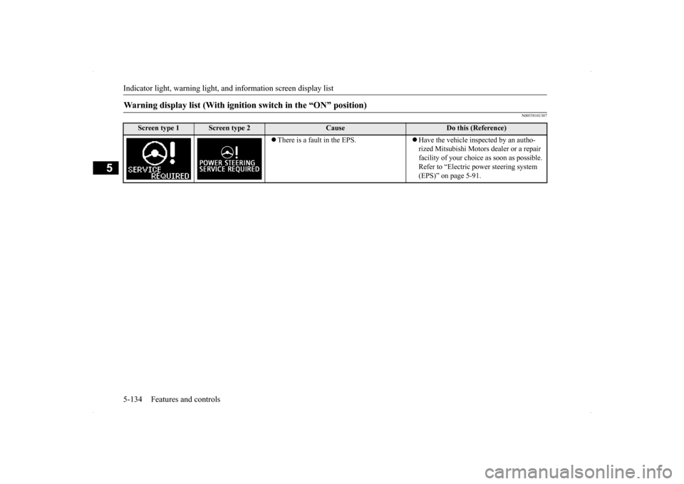
There is a fault in the EPS.
Have the vehicle inspected by an autho- rized Mitsubishi Motors dealer or a repair facility of your choice as soon as possible. Refer to “Electric power steering system (EPS)” on page 5-91.
BK0200700US.book
134 ページ 2013年2月15日 金曜日 午後12時17分
Page 224 of 422
Electric rear window defogger switch
Features and controls 5-157
5
N00523700315
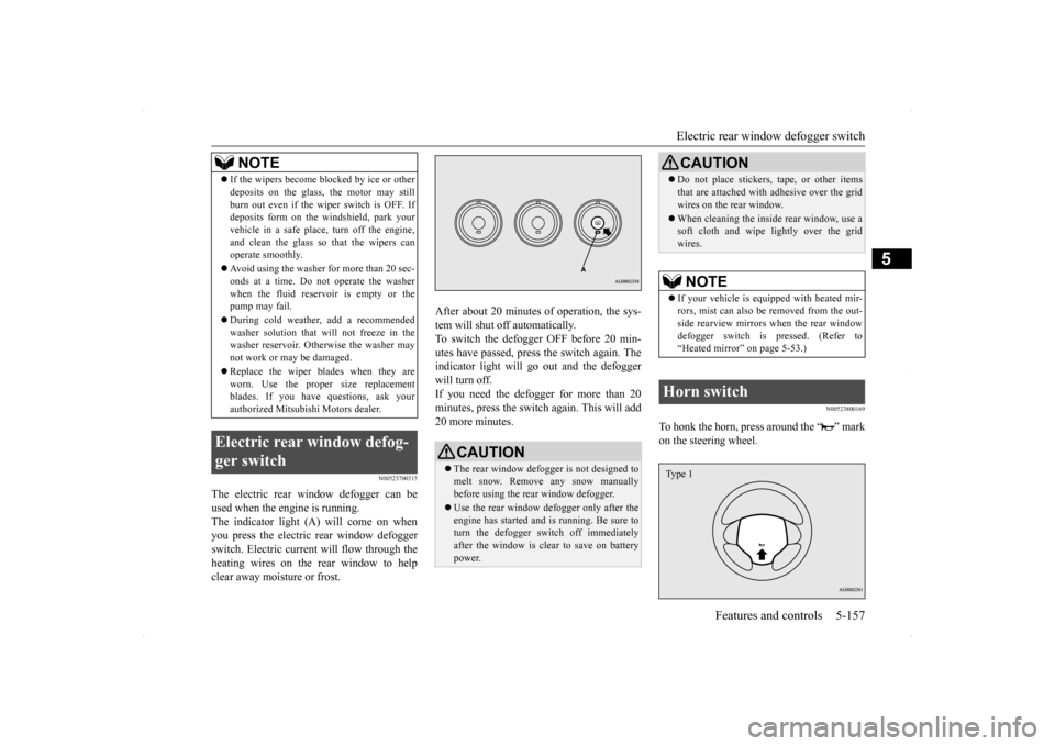
The electric rear window defogger can be used when the engine is running. The indicator light (A) will come on when you press the electric rear window defoggerswitch. Electric current will flow through the heating wires on the rear window to help clear away moisture or frost.
After about 20 minutes of operation, the sys- tem will shut off automatically. To switch the defogger OFF before 20 min-utes have passed, press the switch again. The indicator light will go out and the defogger will turn off. If you need the defogger for more than 20minutes, press the switch
again. This will add
20 more minutes.
N00523800169
To honk the horn, press around the “ ” mark on the steering wheel.
If the wipers become blocked by ice or other deposits on the glass, the motor may still burn out even if the wiper switch is OFF. If deposits form on the windshield, park your vehicle in a safe place, turn off the engine,and clean the glass so that the wipers can operate smoothly. Avoid using the washer for more than 20 sec- onds at a time. Do not operate the washer when the fluid reser
voir is empty or the
pump may fail. During cold weather, add a recommended washer solution that will not freeze in the washer reservoir. Otherwise the washer may not work or may be damaged. Replace the wiper blades when they are worn. Use the proper size replacementblades. If you have questions, ask your authorized Mitsubishi Motors dealer.
Electric rear window defog- ger switch
NOTE
CAUTION The rear window defogger is not designed to melt snow. Remove any snow manuallybefore using the rear window defogger. Use the rear window defogger only after the engine has started and is running. Be sure to turn the defogger switch off immediately after the window is clear to save on batterypower.
Do not place stickers, tape, or other items that are attached with adhesive over the grid wires on the rear window. When cleaning the inside rear window, use a soft cloth and wipe lightly over the grid wires.NOTE
If your vehicle is equipped with heated mir- rors, mist can also be removed from the out-side rearview mirrors when the rear window defogger switch is pressed. (Refer to “Heated mirror” on page 5-53.)
Horn switch
CAUTION
Type 1
BK0200700US.book
157 ページ 2013年2月15日 金曜日 午後12時17分
Page 226 of 422
Bluetooth® 2.0 interface (if so equipped)
Features and controls 5-159
5
Steering control switch and microphone
P.5-159Voice recognition function
P.5-161
Useful voice commands
P.5-162
Speaker enrollment function
P.5-163
Connecting the Bluetooth
® 2.0 interface and
the Bluetooth
® device
P.5-165
Operating a music player connected via Blue- tooth
® P.5-170
How to make or receive hands-free calls
P.5-170 Phonebook function
P.5-172
N00564001112
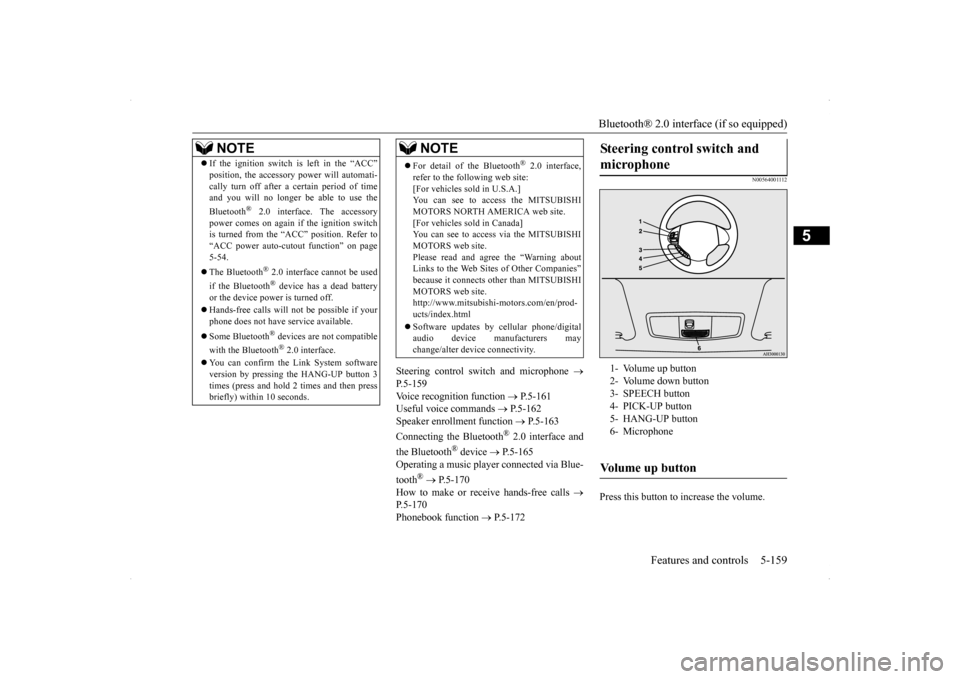
Press this button to increase the volume.
NOTE
If the ignition switch is left in the “ACC” position, the accessory power will automati- cally turn off after a
certain period of time
and you will no longer be able to use the Bluetooth
® 2.0 interface. The accessory
power comes on again if the ignition switch is turned from the “ACC” position. Refer to “ACC power auto-cutout function” on page5-54. The Bluetooth
® 2.0 interface cannot be used
if the Bluetooth
® device has a dead battery
or the device power is turned off. Hands-free calls will not be possible if your phone does not have service available. Some Bluetooth
® devices are not compatible
with the Bluetooth
® 2.0 interface.
You can confirm the Link System software version by pressing the HANG-UP button 3 times (press and hold 2 times and then press briefly) within 10 seconds.
For detail of the Bluetooth
® 2.0 interface,
refer to the following web site:[For vehicles sold in U.S.A.] You can see to access the MITSUBISHI MOTORS NORTH AMERICA web site.[For vehicles sold in Canada] You can see to access via the MITSUBISHI MOTORS web site.Please read and agree the “Warning about Links to the Web Sites of Other Companies” because it connects other than MITSUBISHIMOTORS web site. http://www.mitsubishi-motors.com/en/prod- ucts/index.html Software updates by cellular phone/digital audio device manufacturers maychange/alter device connectivity.NOTE
Steering control switch and microphone
1- Volume up button 2- Volume down button3- SPEECH button 4- PICK-UP button 5- HANG-UP button6- MicrophoneVolume up button
BK0200700US.book
159 ページ 2013年2月15日 金曜日 午後12時17分
Page 266 of 422
Loading information Driving safety 6-7
6
It is important to fami
liarize yourself with the
following terms before loading your vehicle: Vehicle maximum load on the tire: load on an individual tire that is determined by distributing to each axle its share of the maximum loaded vehicle weight anddividing by two. Vehicle normal load on the tire: load on an individual tire that is determined by dis-tributing to each axle its share of the curb weight, accessory weight, and normal occupant weight and dividing by two. Maximum loaded vehicle weight: the sum of - (a) Curb weight;(b) Accessory weight; (c) Vehicle capacity weight; and (d) Production options weight. Curb weight: the weight of a motor vehi- cle with standard equipment including the maximum capacity of fuel, oil, and cool-ant.
Accessory weight: the combined weight (in excess of those standard items which may be replaced) of automatic transmis- sion, power steering, power brakes, powerwindows, power seats, radio, and heater, to the extent that these items are available as factory- installed equipment (whetherinstalled or not). Vehicle capacity weight: the rated cargo and luggage load plus 150 lbs (68 kg)
*
times the vehicle’s designated seatingcapacity. Production options weight: the combined weight of those installed regular produc-tion options weighing over 5 lbs (2.3 kg) in excess of those standard items which they replace, not previously considered incurb weight or accessory weight, includ- ing heavy duty brakes, ride levelers, roof rack, heavy duty battery, and special trim. Normal occupant weight: 150 lbs (68 kg)
*
times the number of specified occupants. (In your vehicle the number is 3) Occupant distribution: distribution of occupants in a vehicle as specified. (In your vehicle the distribution is 2 in front,1 in second row seat)
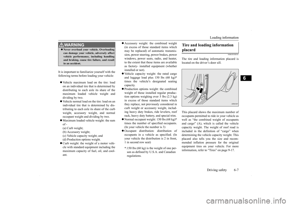
N00630100341
The tire and loading information placard islocated on the driver’s door sill. This placard shows the maximum number of occupants permitted to ride in your vehicle aswell as “the combined weight of occupants and cargo” (A), which is called the vehicle capacity weight. The weight of roof road isincluded in the definition of “cargo” when determining the vehicle capacity weight. This placard also tells you the size and recom-mended inflation pressure for the original equipment tires on your vehicle. For more information, refer to “Tires” on page 9-17.
WA R N I N G Never overload your vehicle. Overloading can damage your vehicle, adversely affect vehicle performance, including handling and braking, cause tire failure, and result in an accident.
* :150 lbs (68 kg) is th
e weight of one per-
son as defined by U.S.A. and Canadian regulations.
Tire and loading information placard
BK0200700US.bo
ok 7 ページ 2013年2月15日 金曜日 午後12時17分
Page 307 of 422
Operation Keys 7-36 Comfort controls
7
N00716300021 N00716400022
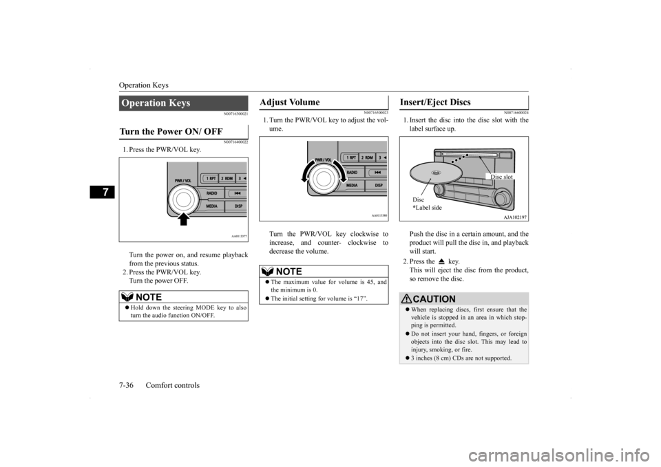
1. Press the PWR/VOL key. Turn the power on, and resume playback from the previous status. 2. Press the PWR/VOL key.Turn the power OFF.
N00716500023
1. Turn the PWR/VOL key to adjust the vol-ume. Turn the PWR/VOL key clockwise to increase, and counter- clockwise todecrease the volume.
N00716600024
1. Insert the disc into the disc slot with thelabel surface up. Push the disc in a certain amount, and the product will pull the disc in, and playbackwill start. 2. Press the key. This will eject the disc from the product, so remove the disc.
Operation Keys Turn the Power ON/ OFF
NOTE
Hold down the steering MODE key to also turn the audio function ON/OFF.
Adjust Volume
NOTE
The maximum value for volume is 45, and the minimum is 0. The initial setting for volume is “17”.
Insert/Eject Discs
CAUTIONWhen replacing discs, first ensure that the vehicle is stopped in an area in which stop-ping is permitted. Do not insert your hand, fingers, or foreign objects into the disc slot. This may lead to injury, smoking, or fire. 3 inches (8 cm) CDs are not supported.Disc * Label side
Disc slot
BK0200700US.bo
ok 36 ページ 2013年2月15日 金曜日 午後12時17分
Page 335 of 422
If the vehicle breaks down 8-2 For emergencies
8
N00836300204
If your vehicle breaks down on the road, move to the shoulder and turn on the hazardwarning flashers. If there is no shoulder, or the shoulder is not safe, drive in the right lane slowly, with the hazard lights flashing, untilyou come to a safe stopping place. Keep the flashers flashing. If the engine stops, there will be no power assist to the steering and brakes, making these difficult to use. The brake booster will not work, so the brakes will not grip well. The brake pedalwill be harder to press than usual. Since there is no power steering assist, the steering wheel will be hard to turn.
Get help from your passengers, bystanders, etc. to push the vehicl
e and move it to a safe
zone.
N00836400654
If the engine cannot be started because the battery is weak or dead, you can start it withthe battery from another vehicle using jumper cables. 1. Take off any metal jewelry such as watch bands or bracelets that might make an accidental electrical contact.
2. Position the vehicles close enough together so that the jumper cables can reach, but be sure the vehicles aren’t touching each other. 3. You could be injured if the vehicles move. Set the parking brake firmly on each vehi- cle. Put an automatic transaxle, CVT or Twin Clutch SST in “P” (PARK) or amanual transaxle in “N” (Neutral). Turn the ignition switch to the “LOCK” posi- tion.
If the vehicle breaks down If the engine stops/fails When the engine fails at the intersection
Jump-starting the engine
WA R N I N G When using jumper cables to start a vehi- cle, follow the procedures and be very cau- tious. CAUTION Do not try to start your vehicle by pushing or towing. Vehicles equipped with continuously variable transmission (CVT) or Twin Clutch SST cannot be started this way. Pushing ortowing a vehicle that has a manual transaxle may overheat and damage the catalytic con- verter. Also, there is more risk of an accidentwhen a vehicle is being pushed or towed.
CAUTION Check the other vehicle. It must have a 12- volt battery. If the other system isn’t 12-volt, both systems can be damaged.WA R N I N G Turn the ignition switch to the “LOCK” position on both vehicles. Make sure thatthe cables or your clothes cannot be caught by the fan or drive belt. Personal injury could result. NOTE
Turn off all lights, heater, and other electrical loads. This will avoid sparks and help saveboth batteries.
BK0200700US.bo
ok 2 ページ 2013年2月15日 金曜日 午後12時17分
Page 350 of 422
9
Vehicle care and maintenanceService precautions ..........
.................................................................9-2
Catalytic converter .
.................................................
..........................9-2
Engine hood ...............................
.......................................................9-3
View of the engine co
mpartment ......................................................9-5
Engine oil and oil filt
er ...........................................
..........................9-5
Engine coolant .................
.................................................................9-8
Air cleaner filter.....
.................................................
..........................9-9
Manual transaxle oil (if so
equipped) .............................................9-10
Continuously variable transmission
(CVT) fluid (if so equipped) . 9-11
Twin Clutch Sportronic shift trans
mission (Twin Clutch SST) fluid (if
so equipped) ...........................
..................................................... 9-11
Transfer oil (All-wheel dr
ive models) ............................................ 9-11
Rear axle oil (All-wheel dr
ive models) .......................................... 9-11
AWC control fluid (if so
equipped) ................................................9-12
Washer fluid .....................
...............................................................9-12
Brake fluid/Clutch fluid (if
so equipped)........................................9-13
Power steering fluid (if so equipped)..............................................9-14 Battery........................................
.....................................................9-14
Tires ...........................................
.....................................................9-17
Clutch pedal free play (if so equipped)...........................................9-24 Brake pedal free play
..............................................
........................9-24
Parking brake lever stroke ..............................................................9-24Parking brake break-in
............................................
........................9-24
Wiper blades ..............................
.....................................................9-25
Emission-control system maintenance ...........................................9-25 General maintenance
..............................................
........................9-26
For cold and snowy weat
her ..........................................................9-27
Fusible links .....................
...............................................................9-28
Fuses ...................................................
............................................ 9-28
Replacement of light bul
bs ....................................
......................... 9-33
Vehicle care precautions
........................................
......................... 9-48
Cleaning the inside of you
r vehicle ................................................ 9-48
Cleaning the outside of your
vehicle .............................................. 9-49
BK0200700US.bo
ok 1 ページ 2013年2月15日 金曜日 午後12時17分
Page 354 of 422
View of the engine compartment
Vehicle care and maintenance 9-5
9
Unlatch the prop from the engine hood and put it back in its retainer. Slowly lower the engine hood about 8 inches (20 cm), then let it drop from its own weight.
N00937600670
N00937701968
It is normal for an engi
ne to use oil. You may
need to add oil between the recommended oil
To close
CAUTION Be careful not to trap your hands or fingers when closing the engine hood. Make sure the engine hood is firmly closed before driving. If you drive without the engine hood com-pletely closed, it could open up while driv- ing.NOTE
If this does not close the engine hood prop- erly, drop it again from a slightly higher position.
Do not push down strongly on the engine hood. Depending on how strongly or where you push down, you could create a dent in the vehicle body. If you drive with the engine hood left open, warning display is displayed on the informa- tion screen in the multi-information display.
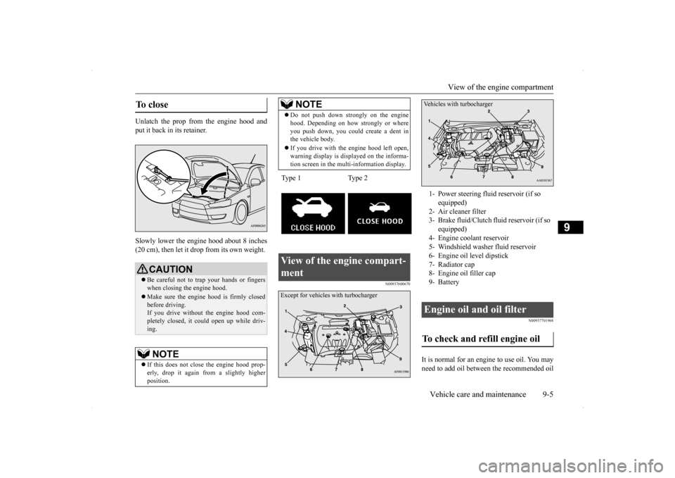
Type 1 Type 2View of the engine compart- ment
NOTE
Except for vehicles with turbocharger
1- Power steering fluid reservoir (if so
equipped)
2- Air cleaner filter 3- Brake fluid/Clutch fluid reservoir (if so
equipped)
4- Engine coolant reservoir 5- Windshield washer fluid reservoir6- Engine oil level dipstick7- Radiator cap 8- Engine oil filler cap 9- Battery Engine oil and oil filter To check and refill engine oil Vehicles with turbocharger
BK0200700US.bo
ok 5 ページ 2013年2月15日 金曜日 午後12時17分