2014 MERCEDES-BENZ SLK ROADSTER light
[x] Cancel search: lightPage 189 of 357
The sensors must be free of dirt, ice and
slush. Otherwise, they may not function cor-
rectly. Clean the sensors regularly, taking
care not to scratch or damage them
(Y page 290).
Front sensors Centre Approx. 100 cm
Corners Approx. 60 cm
Rear sensors
Centre Approx. 120 cm
Corners Approx. 80 cm
Minimum distance
Centre Approx. 20 cm
Corners Approx. 15 cm
If there is an obstacle within this range, the
relevant warning displays light up and a warn- ing tone sounds. If the distance falls below
the minimum, the distance may no longer be
shown.
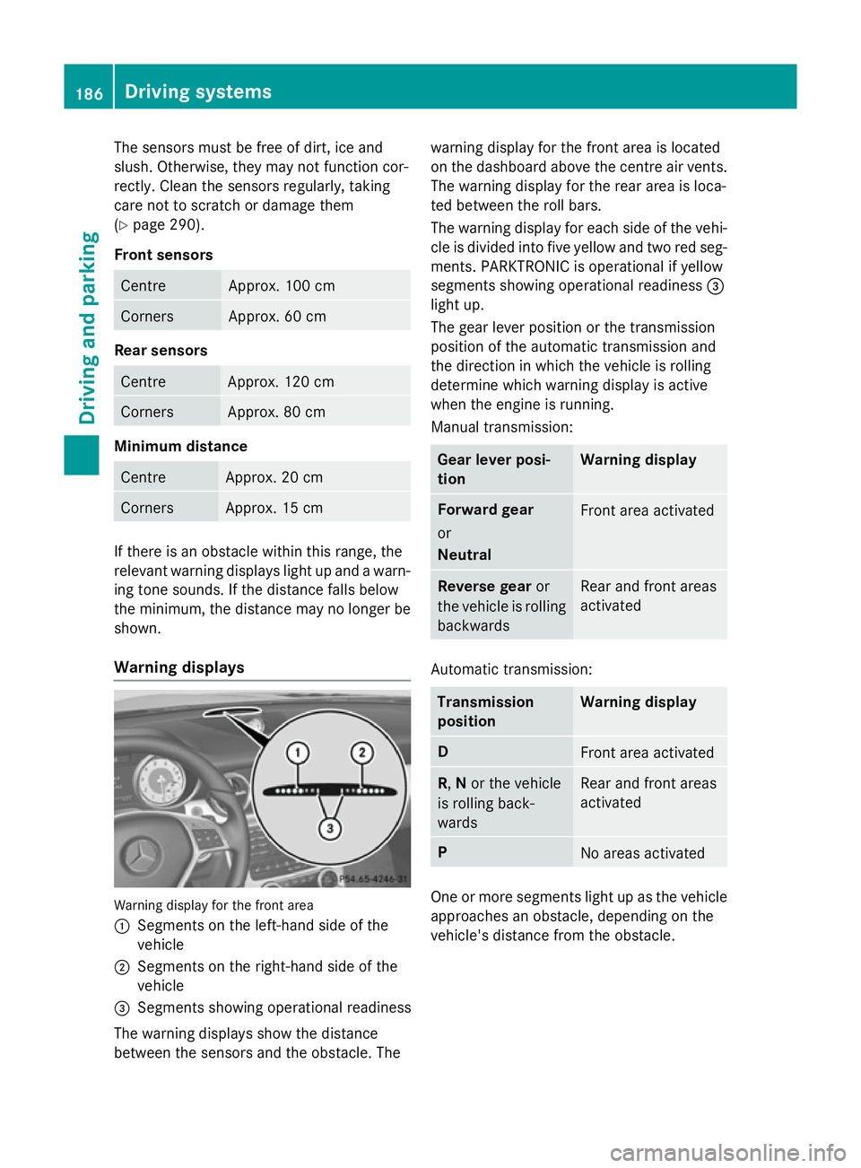
Warning displays Warning display for the front area
: Segments on the left-hand side of the
vehicle
; Segments on the right-hand side of the
vehicle
= Segments showing operational readiness
The warning displays show the distance
between the sensors and the obstacle. The warning display for the front area is located
on the dashboard above the centre air vents.
The warning display for the rear area is loca-
ted between the roll bars.
The warning display for each side of the vehi- cle is divided into five yellow and two red seg-ments. PARKTRONIC is operational if yellow
segments showing operational readiness =
light up.
The gear lever position or the transmission
position of the automatic transmission and
the direction in which the vehicle is rolling
determine which warning display is active
when the engine is running.
Manual transmission: Gear lever posi-
tion Warning display
Forward gear
or
Neutral
Front area activated
Reverse gear
or
the vehicle is rolling backwards Rear and front areas
activated
Automatic transmission:
Transmission
position Warning display
D
Front area activated
R,
Nor the vehicle
is rolling back-
wards Rear and front areas
activated
P
No areas activated
One or more segments light up as the vehicle
approaches an obstacle, depending on the
vehicle's distance from the obstacle. 186
Driving systemsDriving and parking
Page 190 of 357
From the:
R sixth segment onwards, you will hear an
intermittent warning tone for approx-
imately two seconds.
R seventh segment onwards, you will hear a
warning tone for approximately two sec-
onds. This indicates that you have now
reached the minimum distance.
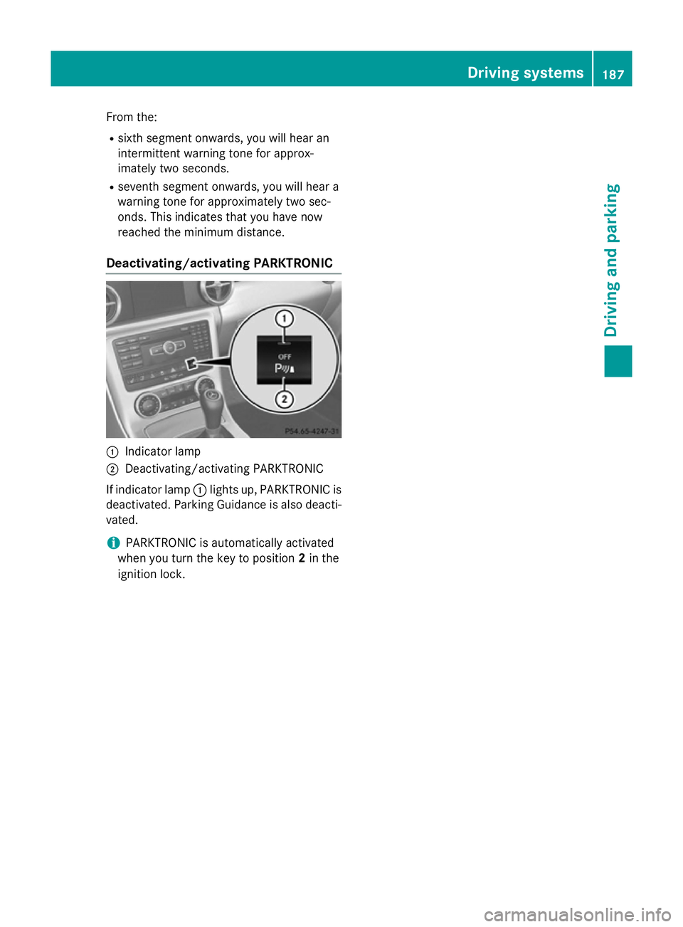
Deactivating/activating PARKTRONIC :
Indicator lamp
; Deactivating/activating PARKTRONIC
If indicator lamp :lights up, PARKTRONIC is
deactivated. Parking Guidance is also deacti-
vated.
i PARKTRONIC is automatically activated
when you turn the key to position 2in the
ignition lock. Driving systems
187Driving and parking Z
Page 191 of 357
Problems with PARKTRONIC
Problem
Possible causes/consequences and
M
MSolutions Only the red segments
in the PARKTRONIC
warning displays are lit.
You also hear a warning
tone for approximately
two seconds.
PARKTRONIC is deacti-
vated after approx-
imately 20 seconds,
and the indicator lamp
in the PARKTRONIC
button lights up. PARKTRONIC has malfunctioned and has switched off.
X If problems persist, have PARKTRONIC checked at a qualified
specialist workshop. Only the red segments
in the PARKTRONIC
warning displays are lit.
PARKTRONIC is deacti-
vated after approx-
imately five seconds. The PARKTRONIC sensors are dirty or there is interference.
X Clean the PARKTRONIC sensors (Y page 290).
X Switch the ignition back on. The problem may be caused by an external source of radio or
ultrasound waves.
X See if PARKTRONIC functions in a different location. Parking Guidance
Important safety notes Parking Guidance is an electronic parking aid
with ultrasound. Ultrasound is used to meas- ure the road on both sides of the vehicle. A
suitable parking space is indicated by the
parking symbol. You receive steering instruc-
tions when parking. You may also use PARK-
TRONIC (Y page 185).
Parking Guidance is only an aid. It is not a
substitute for your attention to the immediate
surroundings. The responsibility for safe
manoeuvring and parking remains with you.
Make sure that there are no persons, animals
or objects in range while manoeuvring and
parking. G
WARNING
If objects are located above the detection
range, Parking Guidance may provide steering instructions too soon. This could cause a col-
lision. There is a risk of an accident.
If objects are located above the detection
range, stop and switch off Parking Assist.
! If unavoidable, you should drive over
obstacles such as kerbs slowly and not at a
sharp angle. Otherwise, you may damage
the wheels or tyres.
When PARKTRONIC is deactivated, Parking
Guidance is also unavailable.
Parking Guidance may also display spaces
not suitable for parking, e.g.: R parking or stopping prohibitions
R in front of driveways or entrances and exits
R unsuitable surfaces 188
Driving systemsDriving and parking
Page 198 of 357
driving in the middle of their lane. This may be
the case if there are vehicles at the edge of
their lane nearest your vehicle.
Due to the nature of the system:
R warnings may be issued in error when driv-
ing close to crash barriers or similar solid
lane borders
R warnings may be interrupted when driving
alongside long vehicles, for example lor-
ries, for a prolonged time
The two radar sensors for Blind Spot Assist
are integrated into the sides of the rear
bumper. Make sure that the bumper is free of dirt, ice or slush in the vicinity of the sensors.
The sensors must not be covered, for exam-
ple by cycle racks or overhanging loads. Fol-
lowing a severe impact or in the event of dam- age to the bumpers, have the function of the
sensors checked at a qualified specialist
workshop. Blind Spot Assist may otherwise
not work properly.
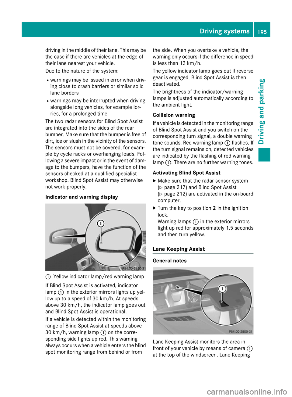
Indicator and warning display :
Yellow indicator lamp/red warning lamp
If Blind Spot Assist is activated, indicator
lamp :in the exterior mirrors lights up yel-
low up to a speed of 30 km/h. At speeds
above 30 km/h, the indicator lamp goes out
and Blind Spot Assist is operational.
If a vehicle is detected within the monitoring
range of Blind Spot Assist at speeds above
30 km/h, warning lamp :on the corre-
sponding side lights up red. This warning
always occurs when a vehicle enters the blind
spot monitoring range from behind or from the side. When you overtake a vehicle, the
warning only occurs if the difference in speed
is less than 12 km/h.
The yellow indicator lamp goes out if reversegear is engaged. Blind Spot Assist is then
deactivated.
The brightness of the indicator/warning
lamps is adjusted automatically according to
the ambient light.
Collision warning
If a vehicle is detected in the monitoring range
of Blind Spot Assist and you switch on the
corresponding turn signal, a double warning
tone sounds. Red warning lamp :flashes. If
the turn signal remains on, detected vehicles
are indicated by the flashing of red warning
lamp :. There are no further warning tones.
Activating Blind Spot Assist
X Make sure that the radar sensor system
(Y page 217) and Blind Spot Assist
(Y page 212) are activated in the on-board
computer.
X Turn the key to position 2in the ignition
lock.
Warning lamps :in the exterior mirrors
light up red for approximately 1.5 seconds
and then turn yellow.
Lane Keeping Assist General notes
Lane Keeping Assist monitors the area in
front of your vehicle by means of camera
:
at the top of the windscreen. Lane Keeping Driving systems
195Driving and parking Z
Page 199 of 357
Assist detects lane markings on the road and
warns you before you leave your lane unin-
tentionally.
If you select km kmon the on-board computer in
the Display unit Speed-/odometer
Display unit Speed-/odometer func-
tion (Y page 213), Lane Keeping Assist is
active starting at a speed of 60 km/h. If the
miles
miles display unit is selected, the assistance
range begins at 40 mph.
A warning may be given if a front wheel
passes over a lane marking. It will warn you by
means of intermittent vibration through the
steering wheel for up to 1.5 second s.
Im portant safety notes G
WARNING
Lane Keeping Assist cannot always clearly
identify lane markings.
In these cases, Lane Keeping Assist may:
R give an unnecessary warning
R not give a warning
There is a risk of an accident.
Always pay particular attention to the traffic
situation and keep in lane, especially if Lane
Keeping Assist alerts you. G
WARNING
The Lane Keeping Assist warning does not
return the vehicle to the original lane. There is a risk of an accident.
Always steer, apply the brakes or accelerate
the vehicle yourself, especially if Lane Keep-
ing Assist alerts you.
If you fail to adapt your driving style, Lane
Keeping Assist can neither reduce the risk of
an accident nor override the laws of physics. Lane Keeping Assist cannot take into account
road, weather or traffic conditions. Lane
Keeping Assist is only an aid. You are respon- sible for the distance to the vehicle in front,
for vehicle speed, for braking in good time,
and for staying in lane.
Lane Keeping Assist does not keep your vehi-
cle in its lane. The system may be impaired or may not func-
tion if:
R there is poor visibility, e.g. due to insuffi-
cient illumination of the road, or due to
snow, rain, fog or spray
R there is glare, e.g. from oncoming traffic,
the sun or reflection from other vehicles
(e.g. if the road surface is wet)
R the windscreen is dirty, misted up, dam-
aged or covered, for instance by a sticker,
in the vicinity of the camera
R no, or several, unclear lane markings are
present for one lane, e.g. in a construction
area
R the lane markings are worn away, dark or
covered up, e.g. by dirt or snow
R the distance to the vehicle in front is too
small and the lane markings thus cannot be
detected
R the lane markings change quickly, e.g.
lanes branch off, cross one another or
merge
R the road is narrow and winding
R there are highly variable shade conditions
on the road
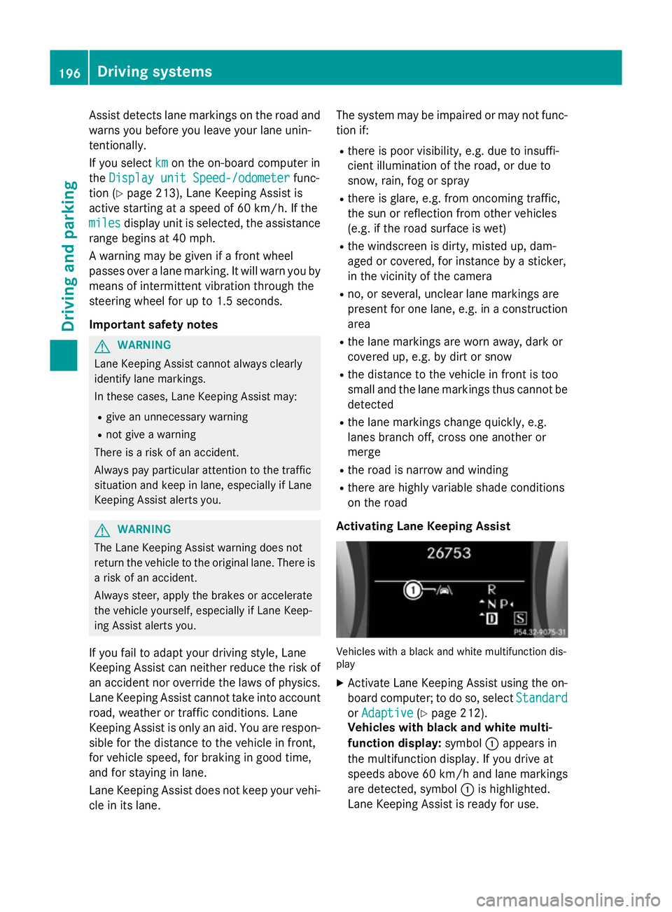
Activating Lane Keeping Assist Vehicles with a black and white multifunction dis-
play
X Activate Lane Keeping Assist using the on-
board computer; to do so, select Standard Standard
or Adaptive
Adaptive (Ypage 212).
Vehicles with black and white multi-
function display: symbol:appears in
the multifunction display. If you drive at
speeds above 60 km/h and lane markings
are detected, symbol :is highlighted.
Lane Keeping Assist is ready for use. 196
Driving systemsDriving and parking
Page 203 of 357
Useful information
i This Owner's Manual describes all mod-
els, series and optional equipment for your
vehicle that were available at the time of
going to press. National variations are pos- sible. Note that your vehicle may not be
equipped with all of the functions descri-
bed. This is also the case for systems and
functions relevant to safety.
i Read the information on qualified special-
ist workshops: (Y page 24). Important safety notes
G
WARNING
Operating the integrated information systems and communications equipment in the vehicle
while driving will distract you from traffic con-
ditions. You could then lose control of the
vehicle. There is a risk of an accident.
Only operate these devices if road traffic con-
ditions permit. If you are unsure about the
surrounding conditions, pull over to a safe
location and make entries only while the vehi-
cle is stationary.
You must observe the legal requirements for
the country in which you are currently driving when operating the on-board computer. G
WARNING
If the instrument cluster has failed or mal-
functioned, you may not recognise function
restrictions relevant to safety. The operating
safety of your vehicle may be impaired. There is a risk of an accident.
Drive on carefully. Have the vehicle checked
at a qualified specialist workshop immedi-
ately.
The on-board computer only shows messages
or warnings from certain systems in the mul- tifunction display. You should therefore make
sure your vehicle is operating safely at all times. Otherwise, a vehicle that is not oper-
ating safely may cause an accident.
If the operating safety of your vehicle is
impaired, park the vehicle safely as soon as
possible. Consult a qualified specialist work-
shop.
For an overview, see the instrument panel
illustration (Y
page 30). Displays and operation
Instrument cluster lighting
The lighting in the instrument cluster, in the
displays and the controls in the vehicle inte-
rior can be adjusted using the brightness con-
trol knob.
The brightness control knob is on the bottom left of the instrument cluster (Y page 30).
X Turn the brightness control knob anti-
clockwise or clockwise.
If the light switch is set to Ã,Tor
L, the brightness is dependant upon
the brightness of the ambient light.
i The light sensor in the instrument cluster
automatically controls the brightness of
the multifunction display.
In daylight, the displays in the instrument
cluster are not lit. Coolant temperature gauge
G
WARNING
If you open the bonnet while the engine is
overheating or while there is a fire in the
engine compartment, you could come into
contact with hot gases or other leaking ser-
vice products. There is a danger of injury.
Allow an overheating engine to cool down
before opening the bonnet. If there is a fire in the engine compartment, leave the bonnet
closed and notify the fire brigade. 200
Displays and operationOn-board computer and displays
Page 204 of 357
The coolant temperature gauge is in the
instrument cluster on the right-hand side
(Y page 30).
Under normal operating conditions and with
the specified coolant level, the coolant tem-
perature may rise to 120 †.
At high outside temperatures and when driv-
ing uphill, the coolant temperature may rise
to the end of the scale. Rev counter
! Do not drive in the overrevving range.
Doing so will damage the engine.
The red band in the rev counter indicates the engine's overrevving range.
The fuel supply is interrupted to protect the
engine when the red band is reached. Outside temperature display
You should pay special attention to road con-
ditions when temperatures are around the
freezing point.
Bear in mind that the outside temperature
display indicates the temperature measured
and does not record the road temperature.
The outside temperature display is in the mul- tifunction display (Y page 202).
Changes in the outside temperature are dis-
played after a short delay. Speedometer with segments
The segments in the speedometer indicate
which speed range is available.
R Cruise control activated (Y page 168):
The segments light up from the stored
speed to the maximum speed.
R Variable SPEEDTRONIC activated
(Y page 180):
The segments light up from the start of the
scale to the selected limit speed.
R DISTRONIC PLUS activated (Y page 171):One or two segments in the set speed
range light up.
R DISTRONIC PLUS detects a vehicle in front:
The segments between the speed of the
vehicle in front and the stored speed light
up. Operating the on-board computer
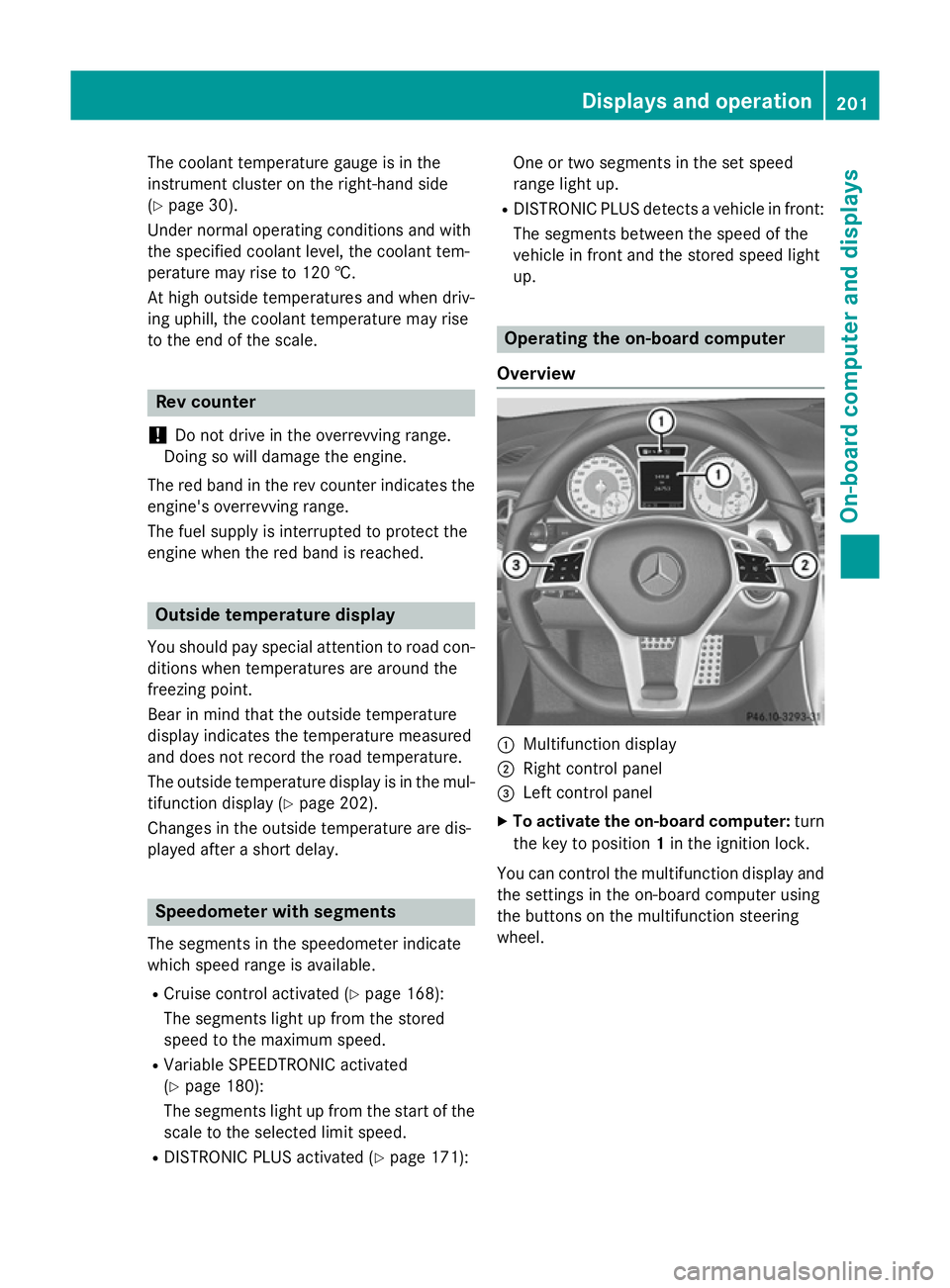
Overview :
Multifunction display
; Right control panel
= Left control panel
X To activate the on-board computer: turn
the key to position 1in the ignition lock.
You can control the multifunction display and
the settings in the on-board computer using
the buttons on the multifunction steering
wheel. Displays and operation
201On-board computer and displays Z
Page 216 of 357
R
Checking the tyre pressure electronically
(Y page 320)
R Calling up the service due date
(Y page 285) Settings menu
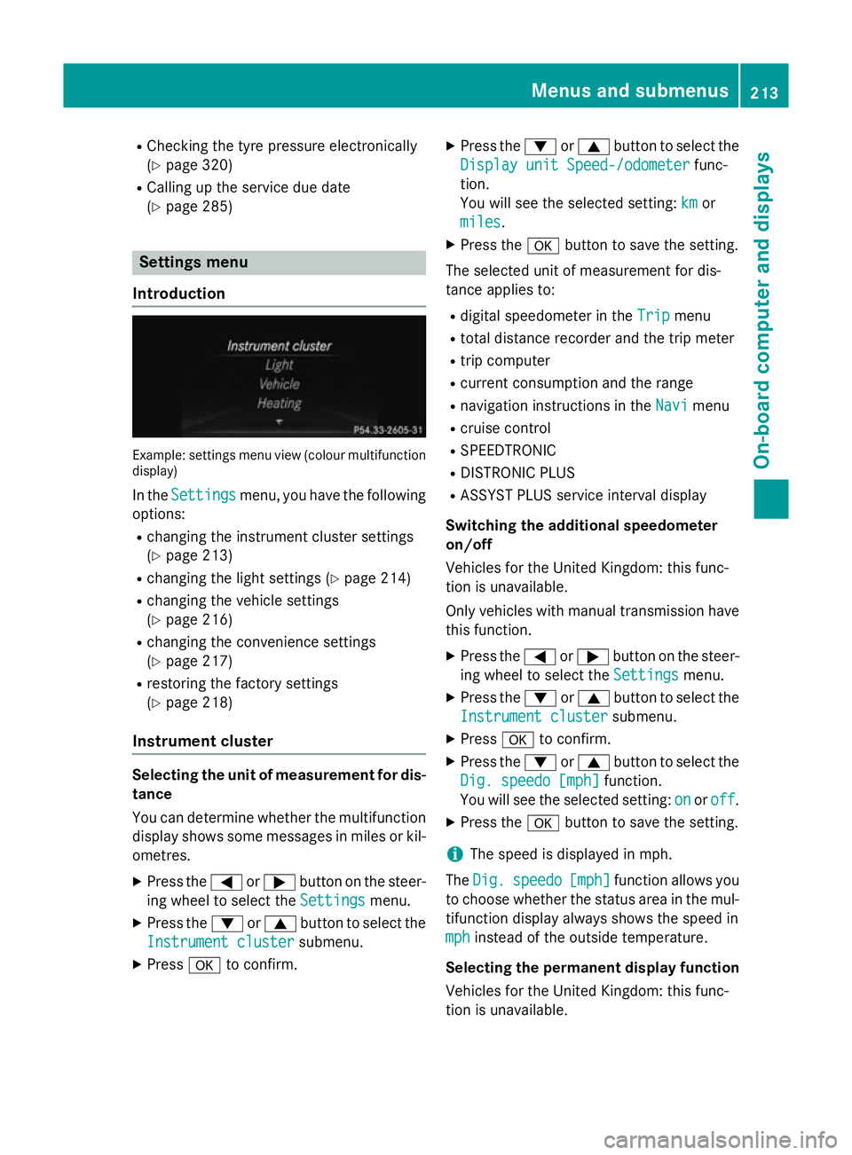
Introduction Example: settings menu view (colour multifunction
display)
In the Settings
Settings menu, you have the following
options:
R changing the instrument cluster settings
(Y page 213)
R changing the light settings (Y page 214)
R changing the vehicle settings
(Y page 216)
R changing the convenience settings
(Y page 217)
R restoring the factory settings
(Y page 218)
Instrument cluster Selecting the unit of measurement for dis-
tance
You can determine whether the multifunction
display shows some messages in miles or kil- ometres.
X Press the =or; button on the steer-
ing wheel to select the Settings
Settings menu.
X Press the :or9 button to select the
Instrument cluster Instrument cluster submenu.
X Press ato confirm. X
Press the :or9 button to select the
Display unit Speed-/odometer
Display unit Speed-/odometer func-
tion.
You will see the selected setting: km kmor
miles
miles.
X Press the abutton to save the setting.
The selected unit of measurement for dis-
tance applies to:
R digital speedometer in the Trip Tripmenu
R total distance recorder and the trip meter
R trip computer
R current consumption and the range
R navigation instructions in the Navi Navimenu
R cruise control
R SPEEDTRONIC
R DISTRONIC PLUS
R ASSYST PLUS service interval display
Switching the additional speedometer
on/off
Vehicles for the United Kingdom: this func-
tion is unavailable.
Only vehicles with manual transmission have this function.
X Press the =or; button on the steer-
ing wheel to select the Settings Settingsmenu.
X Press the :or9 button to select the
Instrument cluster
Instrument cluster submenu.
X Press ato confirm.
X Press the :or9 button to select the
Dig. speedo [mph]
Dig. speedo [mph] function.
You will see the selected setting: on
onoroff
off .
X Press the abutton to save the setting.
i The speed is displayed in mph.
The Dig.
Dig. speedo
speedo [mph]
[mph]function allows you
to choose whether the status area in the mul- tifunction display always shows the speed in
mph
mph instead of the outside temperature.
Selecting the permanent display function
Vehicles for the United Kingdom: this func-
tion is unavailable. Menus and submenus
213On-board computer and displays Z