2014 MERCEDES-BENZ SLK ROADSTER set clock
[x] Cancel search: set clockPage 83 of 357
When a locked door is opened from inside the
vehicle, the previous unlocking process will
be observed if the vehicle has been:
R locked with the locking button for the cen-
tral locking or
R locked automatically
The vehicle will be fully unlocked if it had pre- viously been fully unlocked. Only the door
which has been opened from the inside is
unlocked if only the driver's door had been
previously unlocked. Automatic locking feature
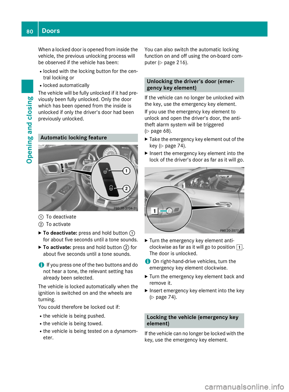
:
To deactivate
; To activate
X To deactivate: press and hold button :
for about five seconds until a tone sounds.
X To activate: press and hold button ;for
about five seconds until a tone sounds.
i If you press one of the two buttons and do
not hear a tone, the relevant setting has
already been selected.
The vehicle is locked automatically when the
ignition is switched on and the wheels are
turning.
You could therefore be locked out if:
R the vehicle is being pushed.
R the vehicle is being towed.
R the vehicle is being tested on a dynamom-
eter. You can also switch the automatic locking
function on and off using the on-board com-
puter (Y page 216). Unlocking the driver's door (emer-
gency key element)
If the vehicle can no longer be unlocked with
the key, use the emergency key element.
If you use the emergency key element to
unlock and open the driver's door, the anti-
theft alarm system will be triggered
(Y page 68).
X Take the emergency key element out of the
key (Y page 74).
X Insert the emergency key element into the
lock of the driver's door as far as it will go. X
Turn the emergency key element anti-
clockwise as far as it will go to position 1.
The door is unlocked.
i On right-hand-drive vehicles, turn the
emergency key element clockwise.
X Turn the emergency key element back and
remove it.
X Insert emergency key element into the key
(Y page 74). Locking the vehicle (emergency key
element)
If the vehicle can no longer be locked with the key, use the emergency key element. 80
DoorsOpening and closing
Page 132 of 357
the front-passenger side as well. The indi-
cator lamp in the ábutton goes out.
R Use the residual heat function if you want to
heat or ventilate the vehicle interior when
the ignition is switched off. The residual
heat function can only be activated or deac-
tivated with the ignition switched off.
ECO start/stop function During automatic engine switch-off, the cli-
mate control only operates at a reduced capa- city. If you require full climate control capa-
city, the ECO start/stop function can be
deactivated by pressing the ECO button
(Y page 148). Operating the climate control system
Switching climate control on/off
General notes When the climate control is switched off, the
air supply and air circulation are also
switched off. The windows could mist up.
Therefore, only switch off climate control
briefly.
i Activate climate control primarily using
the à button (Y page 131).
Air-conditioning system X
Turn the key to position 2in the ignition
lock (Y page 141).
X To switch on: turn airflow control C
clockwise to the desired position (except
position 0) (Ypage 127).
X To switch off: turn airflow control Canti-
clockwise to position 0(Ypage 127). THERMOTRONIC automatic climate
control X
Turn the key to position 2in the ignition
lock (Y page 141).
X To switch on: press theÃbutton.
The indicator lamp in the Ãbutton lights
up. Airflow and air distribution are set to
automatic mode.
or
X Press the ^button.
The indicator lamp in the ^button goes
out. The previous settings are reactivated.
X To switch off: press the^button.
The indicator lamp in the ^button lights
up. Activating/deactivating the cooling
with air dehumidification function
General notes If you deactivate the "Cooling with air-dehu-
midification" function, the air inside the vehi-
cle will not be cooled. The air inside the vehi-
cle will also not be dehumidified. The win-
dows can mist up more quickly. Therefore,
only switch off cooling with air dehumidifica-
tion for a short period.
The "Cooling with air dehumidification" func-
tion is only available when the engine is run-
ning. The air inside the vehicle is cooled and
dehumidified according to the temperature
selected.
Condensation may drip from the underside of the vehicle when cooling mode is active. Thisis normal and not a sign that there is a mal-
function. Operating the climate control system
129Climate control
Page 134 of 357
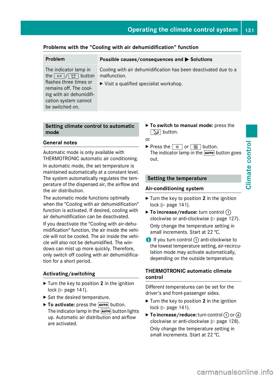
Problems with the "Cooling with air dehumidification" function
Problem
Possible causes/consequences and
M
MSolutions The indicator lamp in
the
¿/Á button
flashes three times or
remains off. The cool-
ing with air dehumidifi-
cation system cannot
be switched on. Cooling with air dehumidification has been deactivated due to a
malfunction.
X Visit a qualified specialist workshop. Setting climate control to automatic
mode
General notes Automatic mode is only available with
THERMOTRONIC automatic air conditioning.
In automatic mode, the set temperature is
maintained automatically at a constant level. The system automatically regulates the tem-
perature of the dispensed air, the airflow and
the air distribution.
The automatic mode functions optimally
when the "Cooling with air dehumidification"
function is activated. If desired, cooling with
air dehumidification can be deactivated.
If you deactivate the "Cooling with air-dehu-
midification" function, the air inside the vehi-
cle will not be cooled. The air inside the vehi- cle will also not be dehumidified. The win-
dows can mist up more quickly. Therefore,
only switch off cooling with air dehumidifica-
tion for a short period.
Activating/switching X
Turn the key to position 2in the ignition
lock (Y page 141).
X Set the desired temperature.
X To activate: press theÃbutton.
The indicator lamp in the Ãbutton lights
up. Automatic air distribution and airflow
are activated. X
To switch to manual mode: press the
_ button.
or X Press the IorK button.
The indicator lamp in the Ãbutton goes
out. Setting the temperature
Air-conditioning system X
Turn the key to position 2in the ignition
lock (Y page 141).
X To increase/reduce: turn control:
clockwise or anti-clockwise (Y page 127).
Only change the temperature setting in
small increments. Start at 22 †.
i If you turn control
:anti-clockwise to
the lowest temperature setting, air-recircu- lation mode may activate automatically,
depending on the outside temperature.
THERMOTRONIC automatic climate
control Different temperatures can be set for the
driver's and front-passenger sides.
X Turn the key to position 2in the ignition
lock (Y page 141).
X To increase/reduce: turn control:orB
clockwise or anti-clockwise (Y page 128).
Only change the temperature setting in
small increments. Start at 22 †. Operating the climate control system
131Climate control
Page 135 of 357
i
If you turn controls
:and Banti-clock-
wise to the lowest temperature setting, air- recirculation mode may activate automati-
cally, depending on the outside tempera-
ture. Setting the air distribution
Air-conditioning system X
Turn the key to position 2in the ignition
lock (Y page 141).
X Press one or more of the P,O,¯
buttons.
The corresponding indicator lamp comes
on.
The air distribution can be set to the following positions:
¯ Directs the airflow through the demis-
ter vents
O Directs the airflow through the foot-
well air vents
P Directs the airflow through the centre
and side air vents
i You can also activate several of the air
distribution settings simultaneously. In
order to do this, press several of the air
distribution buttons. The air is then routed
through different air vents.
THERMOTRONIC automatic climate
control X
Turn the key to position 2in the ignition
lock (Y page 141).
X Press the _button repeatedly until the
desired symbol appears in the display.
The air distribution can be set to the following positions:
P Directs the airflow through the centre
and side air vents
O Directs the airflow through the foot-
well air vents S
Directs the airflow through the centre
and side air vents as well as the foot-
well air vents
¯ Directs the airflow through the demis-
ter vents
b Directs the airflow through the demis-
ter, centre and side air vents
a Directs the airflow through the foot-
well and demister vents
_ Directs the airflow through the demis-
ter, centre, side and footwell air vents
i Regardless of the air distribution setting,
airflow is always directed through the side
air vents. You can only close the side air
vents by fully closing the adjuster on the
side air vents (Y page 136). Setting the airflow
Air-conditioning system X
Turn the key to position 2in the ignition
lock (Y page 141).
X To increase/reduce: turn controlC
clockwise or anti-clockwise (Y page 127).
THERMOTRONIC automatic climate
control X
Turn the key to position 2in the ignition
lock (Y page 141).
X To increase/reduce: press theKor
I button. Switching the ZONE function on/off
This function is only available with
THERMOTRONIC automatic climate control.
X To switch on: press theábutton.
The indicator lamp in the ábutton lights
up. The temperature setting for the driver's 132
Operating the climate control systemClimate control
Page 139 of 357
This could result in burns in the immediate
vicinity of the air vents. There is a risk of injury.
Reduce the heater output before it becomes
too hot.
In order to ensure the direct flow of fresh air
through the air vents into the vehicle interior, please observe the following notes:
R keep the air inlet grille on the bonnet and in
the engine compartment on the front-
passenger side free of blockages, such as
ice, snow or leaves.
R never cover the vents or ventilation grilles
in the vehicle interior.
i You can move the adjusters for the air
vents vertically or horizontally to set the
direction of the airflow.
i Optimal climate control function is ach-
ieved by opening the air vents fully and set- ting the adjusters to the middle position. Setting the centre air vents
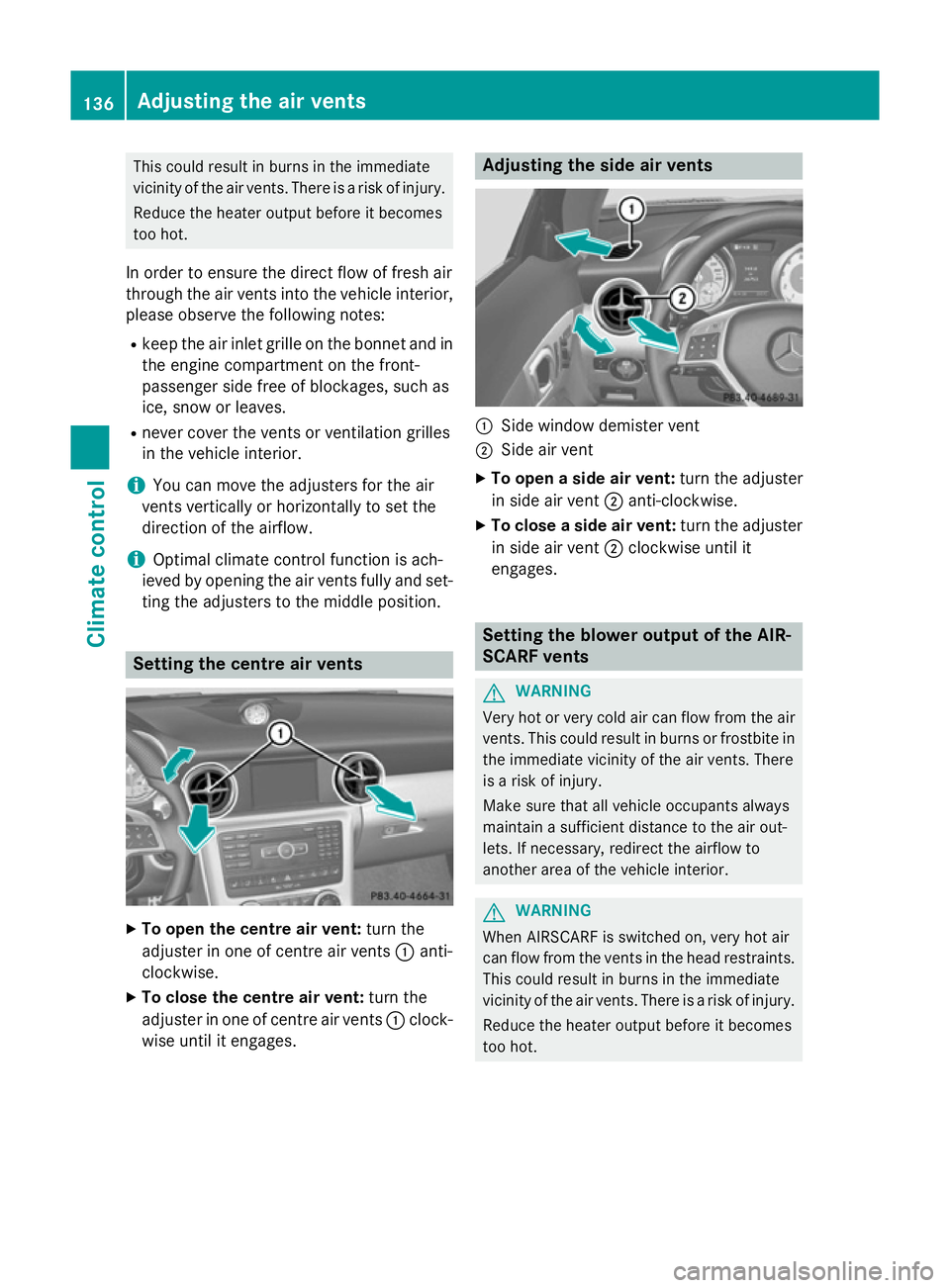
X
To open the centre air vent: turn the
adjuster in one of centre air vents :anti-
clockwise.
X To close the centre air vent: turn the
adjuster in one of centre air vents :clock-
wise until it engages. Adjusting the side air vents
:
Side window demister vent
; Side air vent
X To open a side air vent: turn the adjuster
in side air vent ;anti-clockwise.
X To close a side air vent: turn the adjuster
in side air vent ;clockwise until it
engages. Setting the blower output of the AIR-
SCARF vents
G
WARNING
Very hot or very cold air can flow from the air vents. This could result in burns or frostbite in the immediate vicinity of the air vents. There
is a risk of injury.
Make sure that all vehicle occupants always
maintain a sufficient distance to the air out-
lets. If necessary, redirect the airflow to
another area of the vehicle interior. G
WARNING
When AIRSCARF is switched on, very hot air
can flow from the vents in the head restraints. This could result in burns in the immediate
vicinity of the air vents. There is a risk of injury.
Reduce the heater output before it becomes
too hot. 136
Adjusting the air ventsClimate control
Page 203 of 357
Useful information
i This Owner's Manual describes all mod-
els, series and optional equipment for your
vehicle that were available at the time of
going to press. National variations are pos- sible. Note that your vehicle may not be
equipped with all of the functions descri-
bed. This is also the case for systems and
functions relevant to safety.
i Read the information on qualified special-
ist workshops: (Y page 24). Important safety notes
G
WARNING
Operating the integrated information systems and communications equipment in the vehicle
while driving will distract you from traffic con-
ditions. You could then lose control of the
vehicle. There is a risk of an accident.
Only operate these devices if road traffic con-
ditions permit. If you are unsure about the
surrounding conditions, pull over to a safe
location and make entries only while the vehi-
cle is stationary.
You must observe the legal requirements for
the country in which you are currently driving when operating the on-board computer. G
WARNING
If the instrument cluster has failed or mal-
functioned, you may not recognise function
restrictions relevant to safety. The operating
safety of your vehicle may be impaired. There is a risk of an accident.
Drive on carefully. Have the vehicle checked
at a qualified specialist workshop immedi-
ately.
The on-board computer only shows messages
or warnings from certain systems in the mul- tifunction display. You should therefore make
sure your vehicle is operating safely at all times. Otherwise, a vehicle that is not oper-
ating safely may cause an accident.
If the operating safety of your vehicle is
impaired, park the vehicle safely as soon as
possible. Consult a qualified specialist work-
shop.
For an overview, see the instrument panel
illustration (Y
page 30). Displays and operation
Instrument cluster lighting
The lighting in the instrument cluster, in the
displays and the controls in the vehicle inte-
rior can be adjusted using the brightness con-
trol knob.
The brightness control knob is on the bottom left of the instrument cluster (Y page 30).
X Turn the brightness control knob anti-
clockwise or clockwise.
If the light switch is set to Ã,Tor
L, the brightness is dependant upon
the brightness of the ambient light.
i The light sensor in the instrument cluster
automatically controls the brightness of
the multifunction display.
In daylight, the displays in the instrument
cluster are not lit. Coolant temperature gauge
G
WARNING
If you open the bonnet while the engine is
overheating or while there is a fire in the
engine compartment, you could come into
contact with hot gases or other leaking ser-
vice products. There is a danger of injury.
Allow an overheating engine to cool down
before opening the bonnet. If there is a fire in the engine compartment, leave the bonnet
closed and notify the fire brigade. 200
Displays and operationOn-board computer and displays
Page 306 of 357
i
If the power supply has been interrupted,
e.g. if the battery was discharged, you will
have to:
R set the clock; see the separate operating
instructions.
On vehicles with COMAND Online and a
navigation system, the clock is set auto-
matically.
R reset the function for folding the exterior
mirrors in/out automatically, by folding
the mirrors out once (Y page 104).Charging the battery
G
WARNING
During charging and jump-starting, explosive
gases can escape from the battery. There is a risk of an explosion.
Particularly avoid fire, naked flames, creating
sparks and smoking. Ensure there is sufficient
ventilation while charging and jump-starting.
Do not lean over a battery. G
WARNING
Battery acid is caustic. There is a risk of injury. Avoid contact with the skin, eyes or clothing.
Do not inhale any battery gases. Do not lean
over the battery. Keep children away from
batteries. Wash battery acid immediately with water and seek medical attention. G
WARNING
A discharged battery can freeze at tempera-
tures below freezing point. When jump-start-
ing the vehicle or charging the battery, gases can escape from the battery. There is a risk of
an explosion.
Allow the frozen battery to thaw out before
charging it or jump-starting.
! Only charge the installed battery with a
battery charger which has been tested and
approved by Mercedes-Benz. These battery chargers allow the battery to be charged
while still installed in the vehicle. !
Only use battery chargers with a maxi-
mum charging voltage of 14.8 V.
! Only
charge the battery using the jump-
start connection point.
The jump-starting connection point is in the
engine compartment.
If the indicator/warning lamps do not light up at low temperatures, it is very likely that the
discharged battery has frozen. In this case
you may neither jump-start the vehicle nor
charge the battery. The service life of a bat-
tery that has been thawed may be reduced.
The starting characteristics may be impaired,
especially at low temperatures. Have the
thawed battery checked at a qualified spe-
cialist workshop.
Read the battery charger's operating instruc- tions before charging the battery.
X Open the bonnet.
X Connect the battery charger to the positive
terminal and earth point in the same order
as when connecting the donor battery in
the jump-starting procedure (Y page 304). Battery (vehicle)
303Breakdown assistance Z
Page 311 of 357
The mountings for the removable towing eyes
are located in the bumpers. They are at the
front and at the rear under the covers.
X Press the mark on cover :inwards in the
direction of the arrow.
X Remove cover :from the opening.
X Remove the towing eye from the vehicle
tool kit (Y page 295).
X Screw the towing eye in clockwise to the
stop and tighten it.
Removing the towing eye X
Loosen the towing eye and unscrew it.
X Attach cover :to the bumper and press
until it engages.
X Place the towing eye in the vehicle tool kit
(Y page 295). Towing the vehicle with the rear axle
raised
! The ignition must be switched off if you
are towing the vehicle with the rear axle
raised. Intervention by ESP ®
could other-
wise damage the brake system.
X Switch on the hazard warning lamps
(Y page 113).
X Move the front wheels to the straight-
ahead position.
X Turn the key in the ignition lock to position
0 and remove the key from the ignition
lock.
X When leaving the vehicle, take the key or
the KEYLESS-GO key with you.
When towing your vehicle with the rear axle
raised, it is important that you observe the
safety instructions (Y page 306). Towing the vehicle with both axles on
the ground G
WARNING
If the steering wheel lock is engaged, the vehi- cle can no longer be steered. There is a risk of
an accident.
Always switch on the ignition when towing
with a tow rope or a towing bar.
X Switch on the hazard warning lamps
(Y page 113).
i When towing with the hazard warning
lamps switched on, use the combination
switch as usual to signal a change of direc- tion. In this case, only the turn signals for
the desired direction flash. When the com- bination switch is reset, the hazard warning lamps start flashing again.
X Turn the key to position 2in the ignition
lock.
X When the vehicle is stationary, depress the
brake pedal and keep it depressed.
X Vehicles with manual transmission:
depress the clutch pedal fully and shift to
neutral.
or
X Vehicles with automatic transmission:
shift the automatic transmission to posi-
tion N.
X Release the brake pedal.
X Release the electric parking brake.
It is important that you observe the safety
instructions when towing away your vehicle
(Y page 306). Transporting the vehicle
! You may only secure the vehicle by the
wheels, not by parts of the vehicle such as
axle or steering components. Otherwise,
the vehicle could be damaged.
The towing eye can be used to pull the vehicle
onto a trailer or transporter for transport pur-
poses. 308
Towing and tow-startingBreakdown assistance