2014 MERCEDES-BENZ S-Class seats
[x] Cancel search: seatsPage 330 of 434
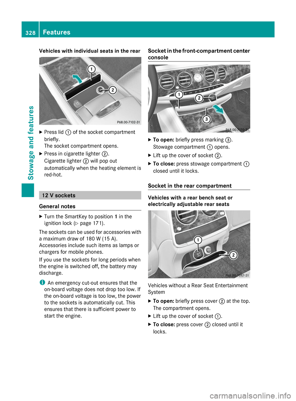
Vehicles with individual seats in the rear
X
Press lid 0043of the socket compartment
briefly.
The socket compartment opens.
X Press in cigarette lighter 0044.
Cigarette lighter 0044will pop out
automatically when the heating element is
red-hot. 12 V sockets
General notes X
Turn the SmartKey to position 1in the
ignition lock (Y page 171).
The sockets can be used for accessories with
a maximum draw of 180 W (15 A).
Accessories include such items as lamps or
chargers for mobile phones.
If you use the sockets for long periods when
the engine is switched off, the battery may
discharge.
i An emergency cut-out ensures that the
on-board voltage does not drop too low. If
the on-board voltage is too low, the power
to the sockets is automatically cut. This
ensures that there is sufficient power to
start the engine. Socket in the front-compartment center
console
X
To open: briefly press marking 0087.
Stowage compartment 0043opens.
X Lift up the cover of socket 0044.
X To close: press stowage compartment 0043
closed until it locks.
Socket in the rear compartment Vehicles with a rear bench seat or
electrically adjustable rear seats
Vehicles without a Rear Seat Entertainment
System
X
To open: briefly press cover 0044at the top.
The compartment opens.
X Lift up the cover of socket 0043.
X To close: press cover 0044closed until it
locks. 328
FeaturesStowage and features
Page 331 of 434
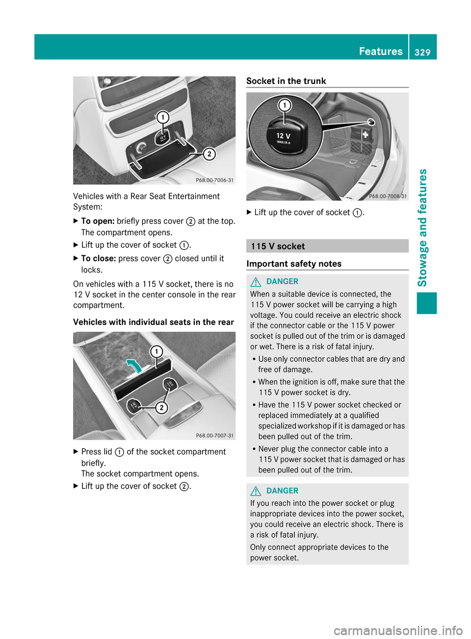
Vehicles with a Rear Seat Entertainment
System:
X
To open: briefly press cover 0044at the top.
The compartment opens.
X Lift up the cover of socket 0043.
X To close: press cover 0044closed until it
locks.
On vehicles with a 115 V socket, there is no
12 V socket in the center console in the rear
compartment.
Vehicles with individual seats in the rear X
Press lid 0043of the socket compartment
briefly.
The socket compartment opens.
X Lift up the cover of socket 0044.Socket in the trunk X
Lift up the cover of socket 0043. 115 V socket
Important safety notes G
DANGER
When a suitable device is connected, the
115 V power socket will be carrying a high
voltage. You could receive an electric shock
if the connector cable or the 115 V power
socket is pulled out of the trim or is damaged
or wet. There is a risk of fatal injury.
R Use only connector cables that are dry and
free of damage.
R When the ignition is off, make sure that the
115 V power socket is dry.
R Have the 115 V power socket checked or
replaced immediately at a qualified
specialized workshop if it is damaged or has
been pulled out of the trim.
R Never plug the connector cable into a
115 V power socket that is damaged or has
been pulled out of the trim. G
DANGER
If you reach into the power socket or plug
inappropriate devices into the power socket,
you could receive an electric shock. There is
a risk of fatal injury.
Only connect appropriate devices to the
power socket. Features
329Stowage and features Z
Page 332 of 434
!
Note that work and repairs on the 115 V
power socket should only be carried out by
qualified specialist personnel.
General notes The 115 V power socket provides an
alternating voltage of 115 V so that small
electronic devices can be connected. These
devices, such as games consoles, chargers
and laptops, must not consume more than a
maximum of 150 watts altogether.
Requirements for operation of these devices:
R the electronic device that you connect has
a suitable connector and conforms to
standards specific to the country you are
in.
R the plug of the electronic device is plugged
correctly into 115 V power socket.
R the maximum wattage of the device to be
connected must not exceed 150 watts.
R the on-board power supply is within a
permissible voltage range.
R the 12 V sockets in the center console in
the front compartment (Y page 328) and in
the trunk are functional (Y page 329).
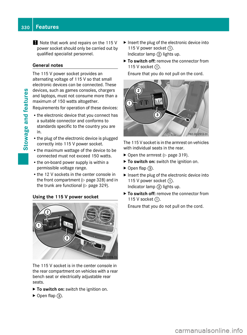
Using the 115 V power socket The 115 V socket is in the center console in
the rear compartment on vehicles with a rear
bench seat or electrically adjustable rear
seats.
X To switch on: switch the ignition on.
X Open flap 0087. X
Insert the plug of the electronic device into
115 V power socket 0043.
Indicator lamp 0044lights up.
X To switch off: remove the connector from
115 V socket 0043.
Ensure that you do not pull on the cord. The 115 V socket is in the armrest on vehicles
with individual seats in the rear.
X Open the armrest (Y page 319).
X To switch on: switch the ignition on.
X Open flap 0087.
X Insert the plug of the electronic device into
115 V power socket 0043.
Indicator lamp 0044lights up.
X To switch off: remove the connector from
115 V socket 0043.
Ensure that you do not pull on the cord. 330
FeaturesStowage and features
Page 372 of 434

G
WARNING
Electrostatic build-up can lead to the creation
of sparks, which could ignite the highly
explosive gases of a battery. There is a risk of
an explosion.
Before handling the battery, touch the vehicle
body to remove any existing electrostatic
build-up.
The highly flammable gas mixture forms when
charging the battery as well as when jump-
starting.
Always make sure that neither you nor the
battery is electrostatically charged. A build-
up of electrostatic charge can be caused, for
example:
R by wearing clothing made from synthetic
fibers
R due to friction between clothing and seats
R if you push or pull the battery across the
carpet or other synthetic materials
R if you wipe the battery with a cloth G
WARNING
During the charging process, a battery
produces hydrogen gas. If a short circuit
occurs or sparks are created, the hydrogen
gas can ignite. There is a risk of an explosion.
R Make sure that the positive terminal of a
connected battery does not come into
contact with vehicle parts.
R Never place metal objects or tools on a
battery.
R It is important that you observe the
described order of the battery terminals
when connecting and disconnecting a
battery.
R When jump-starting, make sure that the
battery poles with identical polarity are
connected.
R It is particularly important to observe the
described order when connecting and
disconnecting the jumper cables.
R Never connect or disconnect the battery
terminals while the engine is running. G
WARNING
Battery acid is caustic. There is a risk of injury.
Avoid contact with the skin, eyes or clothing.
Do not inhale any battery gases. Do not lean
over the battery. Keep children away from
batteries. Wash battery acid immediately with
water and seek medical attention. H
Environmental note Batteries contain dangerous
substances. It is against the
law to dispose of them with
the household rubbish. They
must be collected separately
and recycled to protect the
environment.
Dispose of batteries in an
environmentally friendly
manner. Take discharged
batteries to a qualified
specialist workshop or a
special collection point for
used batteries.
! Have the battery checked regularly at a
qualified specialist workshop.
Observe the service intervals in the
Maintenance Booklet or contact a qualified
specialist workshop for more information.
! You should have all work involving the
battery carried out at a qualified specialist
workshop. In the exceptional case that it is
necessary for you to disconnect the battery
yourself, make sure that:
R secure the vehicle to prevent it from
rolling away.
R you switch off the engine and remove the
SmartKey. Make sure the ignition is
switched off. Check that all the indicator
lamps in the instrument cluster are off.
Otherwise, electronic components, such
as the alternator, may be damaged.
R you first remove the negative terminal
clamp and then the positive terminal
clamp. Never swap the terminal clamps. 370
Battery (vehicle)Breakdown assistance
Page 390 of 434
pressure tables are examples. Tire
pressure specifications are vehicle-specific
and may deviate from the data shown here.
The tire pressure specifications that are
valid for your vehicle can be found on the
Tire and Loading Information placard and
tire pressure table on the vehicle.
General notes The recommended tire pressures for the tires
mounted at the factory can be found on the
labels described here.
Further information on tire pressures can be
obtained at a qualified specialist workshop.
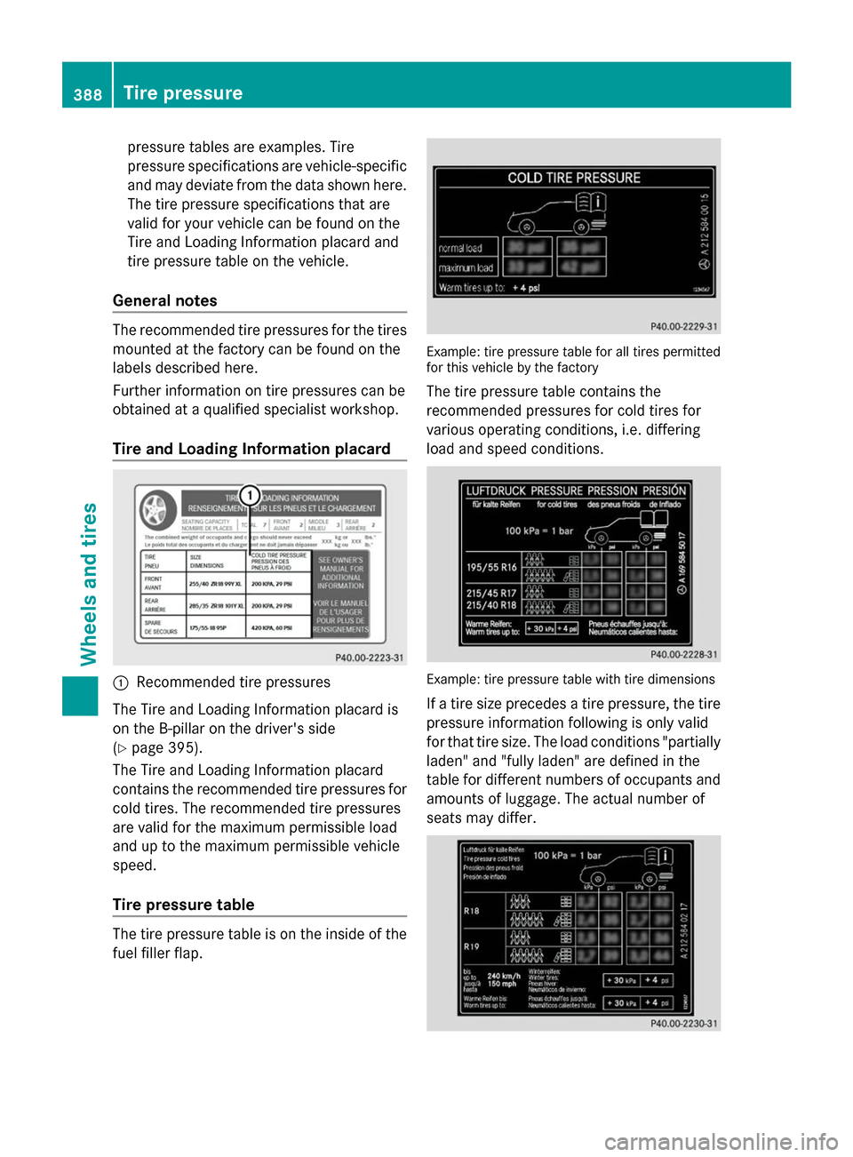
Tire and Loading Information placard 0043
Recommended tire pressures
The Tire and Loading Information placard is
on the B-pillar on the driver's side
(Y page 395).
The Tire and Loading Information placard
contains the recommended tire pressures for
cold tires. The recommended tire pressures
are valid for the maximum permissible load
and up to the maximum permissible vehicle
speed.
Tire pressure table The tire pressure table is on the inside of the
fuel filler flap. Example: tire pressure table for all tires permitted
for this vehicle by the factory
The tire pressure table contains the
recommended pressures for cold tires for
various operating conditions, i.e. differing
load and speed conditions.
Example: tire pressure table with tire dimensions
If a tire size precedes a tire pressure, the tire
pressure information following is only valid
for that tire size. The load conditions "partially
laden" and "fully laden" are defined in the
table for different numbers of occupants and
amounts of luggage. The actual number of
seats may differ.388
Tire pressureWheels and tires
Page 398 of 434
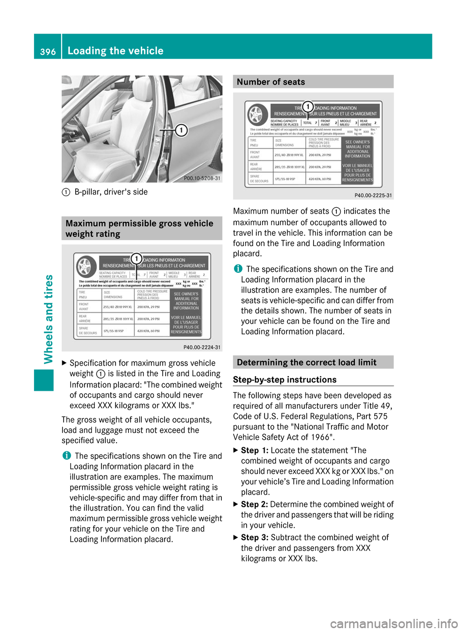
0043
B-pillar, driver's side Maximum permissible gross vehicle
weight rating X
Specification for maximum gross vehicle
weight 0043is listed in the Tire and Loading
Information placard: "The combined weight
of occupants and cargo should never
exceed XXX kilograms or XXX lbs."
The gross weight of all vehicle occupants,
load and luggage must not exceed the
specified value.
i The specifications shown on the Tire and
Loading Information placard in the
illustration are examples. The maximum
permissible gross vehicle weight rating is
vehicle-specific and may differ from that in
the illustration. You can find the valid
maximum permissible gross vehicle weight
rating for your vehicle on the Tire and
Loading Information placard. Number of seats
Maximum number of seats
0043indicates the
maximum number of occupants allowed to
travel in the vehicle. This information can be
found on the Tire and Loading Information
placard.
i The specifications shown on the Tire and
Loading Information placard in the
illustration are examples. The number of
seats is vehicle-specific and can differ from
the details shown. The number of seats in
your vehicle can be found on the Tire and
Loading Information placard. Determining the correct load limit
Step-by-step instructions The following steps have been developed as
required of all manufacturers under Title 49,
Code of U.S. Federal Regulations, Part 575
pursuant to the "National Traffic and Motor
Vehicle Safety Act of 1966".
X
Step 1: Locate the statement "The
combined weight of occupants and cargo
should never exceed XXX kg or XXX lbs." on
your vehicle’s Tire and Loading Information
placard.
X Step 2: Determine the combined weight of
the driver and passengers that will be riding
in your vehicle.
X Step 3: Subtract the combined weight of
the driver and passengers from XXX
kilograms or XXX lbs. 396
Loading the vehicleWheels and tires
Page 409 of 434

Occupant distribution
The distribution of occupants in a vehicle at
their designated seating positions.
Total load limit
Nominal load and luggage load plus 68 kg
(150 lbs) multiplied by the number of seats in
the vehicle. Changing a wheel
Flat tire
The "Breakdown assistance" section
(Y page 365)c ontains information and notes
on how to deal with a flat tire. Information on
driving with MOExtended tires in the event of
a flat tire can be found under "MOExtended
tires (tires with run-flat characteristics"
(Y page 365). Rotating the wheels
G
WARNING
Interchanging the front and rear wheels may
severely impair the driving characteristics if
the wheels or tires have different dimensions.
The wheel brakes or suspension components
may also be damaged. There is a risk of
accident.
Rotate front and rear wheels only if the wheels
and tires are of the same dimensions.
! On vehicles equipped with a tire pressure
monitor, electronic components are
located in the wheel.
Tire-mounting tools should not be used
near the valve. This could damage the
electronic components.
Only have tires changed at a qualified
specialist workshop.
Always observe the instructions and safety
notes in the "Mounting a wheel" section
(Y page 408).
The wear patterns on the front and rear tires
differ, depending on the operating conditions. Rotate the wheels before a clear wear pattern
has formed on the tires. Front tires typically
wear more on the shoulders and the rear tires
in the center.
If your vehicle's tire configuration allows, you
can rotate the wheels according to the
intervals in the tire manufacturer's warranty
book in your vehicle documents. If no
warranty book is available, the tires should be
rotated every 3,000 to 6,000 miles
(5,000 to
10,000 km), or earlier if tire wear requires.
Ensure the direction of rotation is maintained.
Clean the contact surfaces of the wheel and
the brake disc thoroughly every time a wheel
is rotated. Check the tire pressure and
reactivate the tire pressure monitor if
necessary (Y page 393). Direction of rotation
Tires with a specified direction of rotation
have additional benefits, e.g. if there is a risk
of hydroplaning. You will only gain these
benefits if the correct direction of rotation is
maintained.
An arrow on the sidewall of the tire indicates
its correct direction of rotation. Storing wheels
Store wheels that are not being used in a cool,
dry and preferably dark place. Protect the
tires from oil, grease, gasoline and diesel. Cleaning the wheels
G
WARNING
The water jet from a circular jet nozzle (dirt
blasters) can cause invisible exterior damage
to the tires or chassis components.
Components damaged in this way may fail
unexpectedly. There is a risk of an accident.
Do not use power washers with circular jet
nozzles to clean the vehicle. Have damaged Changing a wheel
407Wheels and tires
Z