2014 MERCEDES-BENZ S-Class warning
[x] Cancel search: warningPage 323 of 434
X
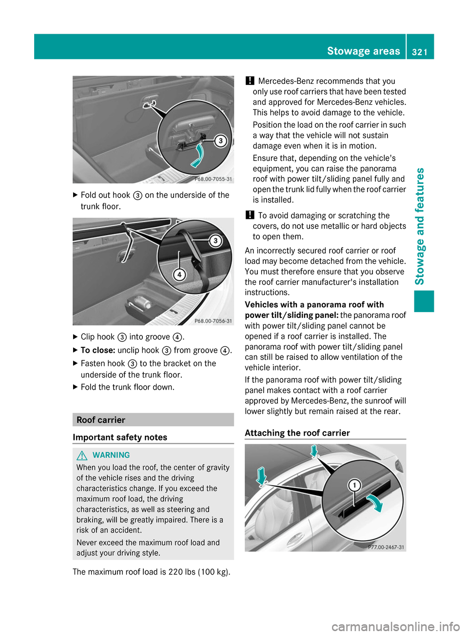
Fold out hook 0087on the underside of the
trunk floor. X
Clip hook 0087into groove 0085.
X To close: unclip hook 0087from groove 0085.
X Fasten hook 0087to the bracket on the
underside of the trunk floor.
X Fold the trunk floor down. Roof carrier
Important safety notes G
WARNING
When you load the roof, the center of gravity
of the vehicle rises and the driving
characteristics change. If you exceed the
maximum roof load, the driving
characteristics, as well as steering and
braking, will be greatly impaired. There is a
risk of an accident.
Never exceed the maximum roof load and
adjust your driving style.
The maximum roof load is 220 lbs (100 kg). !
Mercedes-Benz recommends that you
only use roof carriers that have been tested
and approved for Mercedes-Benz vehicles.
This helps to avoid damage to the vehicle.
Position the load on the roof carrier in such
a way that the vehicle will not sustain
damage even when it is in motion.
Ensure that, depending on the vehicle's
equipment, you can raise the panorama
roof with power tilt/sliding panel fully and
open the trunk lid fully when the roof carrier
is installed.
! To avoid damaging or scratching the
covers, do not use metallic or hard objects
to open them.
An incorrectly secured roof carrier or roof
load may become detached from the vehicle.
You must therefore ensure that you observe
the roof carrier manufacturer's installation
instructions.
Vehicles with a panorama roof with
power tilt/sliding panel: the panorama roof
with power tilt/sliding panel cannot be
opened if a roof carrier is installed. The
panorama roof with power tilt/sliding panel
can still be raised to allow ventilation of the
vehicle interior.
If the panorama roof with power tilt/sliding
panel makes contact with a roof carrier
approved by Mercedes-Benz, the sunroof will
lower slightly but remain raised at the rear.
Attaching the roof carrier Stowage areas
321Stowage and features Z
Page 326 of 434
When you use the warming function, the
metal insert of the cup holder is heated.
Therefore, do not touch the cup holder insert.
X Turn the SmartKey to position 2in the
ignition lock (Y page 171).
X To switch on the cooling function: press
and hold button 0044until the blue indicator
lamp on the button lights up.
X To switch on the heating function: press
and hold button 0044until the red indicator
lamp on the button lights up.
X To switch off the function: press and hold
button 0044until the indicator lamp on the
button goes out.
The rubber mat can be removed for cleaning.
Clean with clear, lukewarm water only.
Do not use hard or sharp objects to clean the
cup holder. Use only a soft cloth to clean it. Sun visors
Overview G
WARNING
If the mirror cover of the vanity mirror is folded
up when the vehicle is in motion, you could be
blinded by incident light. There is a risk of an
accident.
Always keep the mirror cover folded down
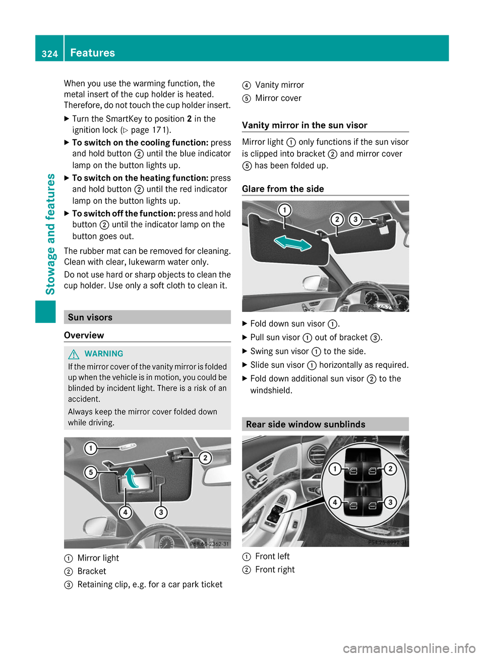
while driving. 0043
Mirror light
0044 Bracket
0087 Retaining clip, e.g. for a car park ticket 0085
Vanity mirror
0083 Mirror cover
Vanity mirror in the sun visor Mirror light
0043only functions if the sun visor
is clipped into bracket 0044and mirror cover
0083 has been folded up.
Glare from the side X
Fold down sun visor 0043.
X Pull sun visor 0043out of bracket 0087.
X Swing sun visor 0043to the side.
X Slide sun visor 0043horizontally as required.
X Fold down additional sun visor 0044to the
windshield. Rear side window sunblinds
0043
Front left
0044 Front right 324
FeaturesStowage and features
Page 327 of 434
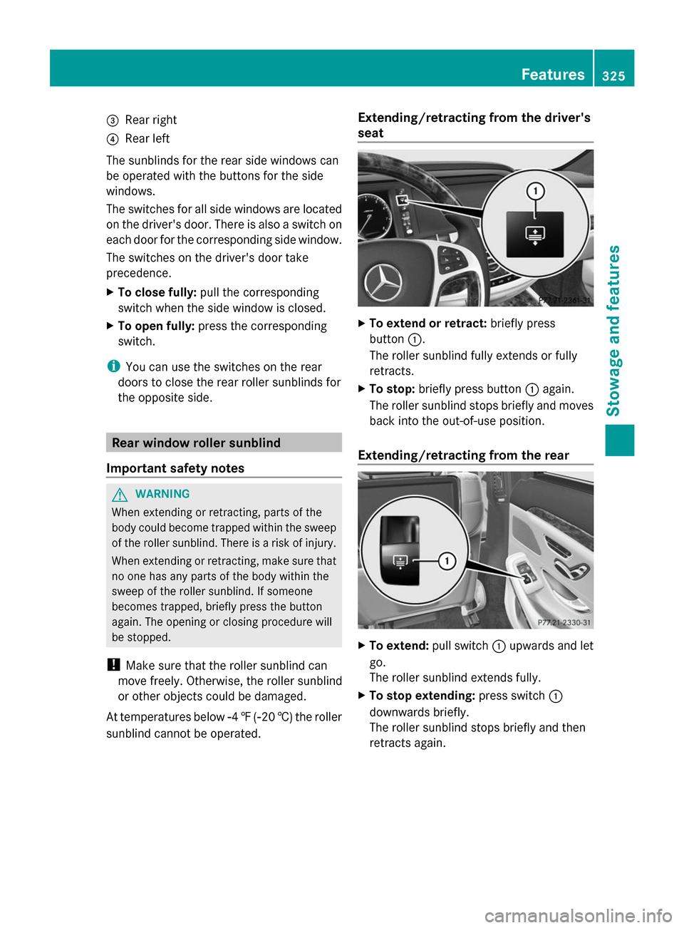
0087
Rear right
0085 Rear left
The sunblinds for the rear side windows can
be operated with the buttons for the side
windows.
The switches for all side windows are located
on the driver's door. There is also a switch on
each door for the corresponding side window.
The switches on the driver's door take
precedence.
X To close fully: pull the corresponding
switch when the side window is closed.
X To open fully: press the corresponding
switch.
i You can use the switches on the rear
doors to close the rear roller sunblinds for
the opposite side. Rear window roller sunblind
Important safety notes G
WARNING
When extending or retracting, parts of the
body could become trapped within the sweep
of the roller sunblind. There is a risk of injury.
When extending or retracting, make sure that
no one has any parts of the body within the
sweep of the roller sunblind. If someone
becomes trapped, briefly press the button
again. The opening or closing procedure will
be stopped.
! Make sure that the roller sunblind can
move freely. Otherwise, the roller sunblind
or other objects could be damaged.
At temperatures below 00F84‡( 00F820 †) the roller
sunblind cannot be operated. Extending/retracting from the driver's
seat
X
To extend or retract: briefly press
button 0043.
The roller sunblind fully extends or fully
retracts.
X To stop: briefly press button 0043again.
The roller sunblind stops briefly and moves
back into the out-of-use position.
Extending/retracting from the rear X
To extend: pull switch0043upwards and let
go.
The roller sunblind extends fully.
X To stop extending: press switch0043
downwards briefly.
The roller sunblind stops briefly and then
retracts again. Features
325Stowage and features Z
Page 328 of 434
X
To retract: press switch 0043beyond the
point of resistance and let go.
The roller sunblind retracts fully.
X To stop retracting: pull switch0043
upwards.
The roller sunblind stops briefly and then
extends again.
When the override feature for the rear side
windows is activated (Y page 70), the switch
0094 cannot be operated. The roller sunblind
can only be extended and retracted from the
driver's seat. Ashtray
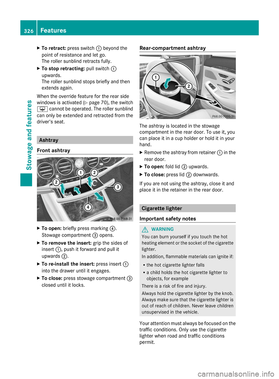
Front ashtray X
To open: briefly press marking 0085.
Stowage compartment 0087opens.
X To remove the insert: grip the sides of
insert 0043, push it forward and pull it
upwards 0044.
X To re-install the insert: press insert0043
into the drawer until it engages.
X To close: press stowage compartment 0087
closed until it locks. Rear-compartment ashtray The ashtray is located in the stowage
compartment in the rear door. To use it, you
can place it in a cup holder or hold it in your
hand.
X
Remove the ashtray from retainer 0043in the
rear door.
X To open: fold lid0044upwards.
X To close: press lid0044downwards.
If you are not using the ashtray, close it and
place it in the retainer in the rear door. Cigarette lighter
Important safety notes G
WARNING
You can burn yourself if you touch the hot
heating element or the socket of the cigarette
lighter.
In addition, flammable materials can ignite if:
R the hot cigarette lighter falls
R a child holds the hot cigarette lighter to
objects, for example
There is a risk of fire and injury.
Always hold the cigarette lighter by the knob.
Always make sure that the cigarette lighter is
out of reach of children. Never leave children
unsupervised in the vehicle.
Your attention must always be focused on the
traffic conditions. Only use the cigarette
lighter when road and traffic conditions
permit. 326
FeaturesSto
wage an d features
Page 333 of 434
Problems with the 115 V power socket
Problem Possible causes/consequences and
0050
0050Solutions The warning lamp on
the 115 V power socket
is not lit. The on-board voltage is too low because the battery is too weak.
X
Start the engine.
or
X Charge the battery (Y page 371).
If the indicator lamp still does not light up:
X Visit a qualified specialist workshop. The temperature of the DC/AC converter is temporarily too high.
X
Remove the electronic device connector from the 115 V socket.
X Let the DC/AC converter cool down.
If the indicator lamp still does not light up after cooling down the
converter:
X Visit a qualified specialist workshop. You have connected an electronic device that has a constant
nominal power of less than 150 watts, but has a very high switch-
on current. This device will not work. If you connect such a device,
the 115 V power socket will not supply it with power.
X Connect a suitable electronic device. Coolbox in the rear compartment
Important safety notes G
WARNING
If you cover the ventilation grille for the
coolbox, it may overheat. There is a risk of fire.
Always make sure that the ventilation grille is
not covered.
The ventilation grille for the coolbox is in the
trunk.
The coolbox can bear a maximum load of
7.7 lb (3.5 kg).
If you want to store a bottle in the upper
compartment of the coolbox, the capacity of
the bottle must not exceed 17 fl. oz. (0.5 l).
Store only plastic bottles in the upper
compartment of the coolbox. Using the coolbox
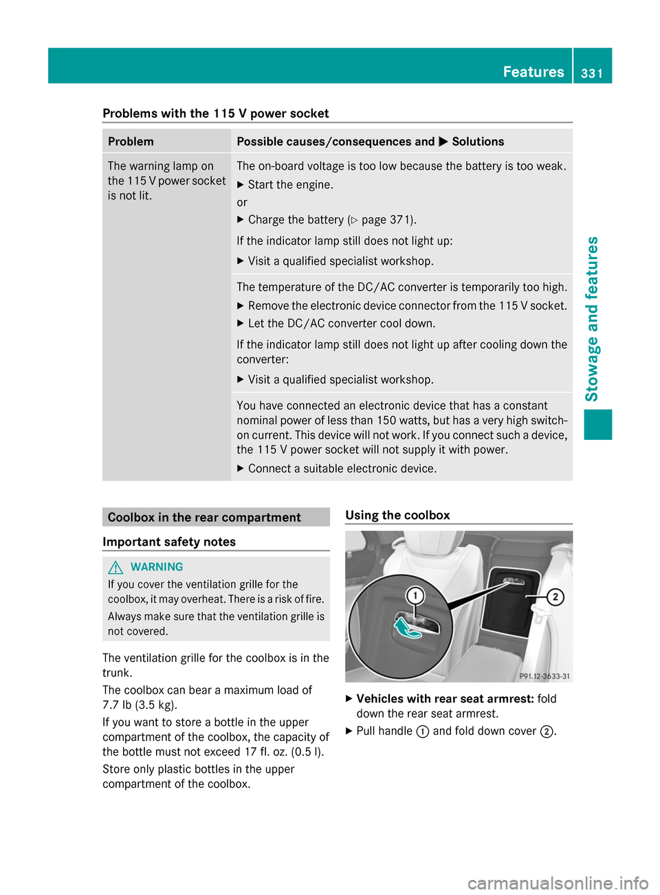
X
Vehicles with rear seat armrest: fold
down the rear seat armrest.
X Pull handle 0043and fold down cover 0044. Features
331Stowage and features Z
Page 336 of 434
Emergency call
Important safety notes
G
WARNING
It can be dangerous to remain in the vehicle,
even if you have pressed the SOS button in an
emergency if:
R you see smoke inside or outside of the
vehicle, e.g. if there is a fire after an
accident
R the vehicle is on a dangerous section of
road
R the vehicle is not visible or cannot easily be
seen by other road users, particularly when
dark or in poor visibility conditions
There is a risk of an accident and injury.
Leave the vehicle immediately in this or
similar situations as soon as it is safe to do
so. Move to a safe location along with other
vehicle occupants. In such situations, secure
the vehicle in accordance with national
regulations, e. g. with a warning triangle.
You must have a license agreement to
activate the mbrace service. Make sure that
your system is activated and operational. To
log in, press the 00D9MB Info call button. If
any of the steps mentioned are not carried
out, the system may not be activated.
If you have questions about the activation,
contact one of the following telephone
hotlines:
Mercedes-Benz Customer Assistance Center
at 1-800-FOR-MERCedes(1-800-367-6372)
or 1-866-990-9007
General notes
An emergency call is dialed automatically if
an air bag or Emergency Tensioning Device is
triggered.
i You cannot end an automatically
triggered emergency call yourself.
An emergency call can also be initiated
manually. As soon as the emergency call has been
initiated, the indicator lamp in the SOS button
flashes. The multifunction display shows the
Connecting Call
Connecting Call message.
The audio output is muted.
Once the connection has been made, the
Call Connected Call Connected message appears in the
multifunction display.
All important information on the emergency
is transmitted, for example:
R Current location of the vehicle (as
determined by the GPS system)
R Vehicle identification number
R Information on the severity of the accident
Shortly after the emergency call has been
initiated, a voice connection is automatically
established between the Customer
Assistance Center and the vehicle occupants.
R If the vehicle occupants respond, the
Mercedes-Benz Customer Assistance
Center attempts to get more information
on the emergency.
R If there is no response from the vehicle
occupants, an ambulance is immediately
sent to the vehicle.
If no voice connection can be established to
the Mercedes-Benz Customer Assistance
Center, the system has been unable to initiate
an emergency call.
This can occur, for example, if the relevant
mobile phone network is not available. The
indicator lamp in the SOS button flashes
continuously.
The Call Failed
Call Failed message appears in the
multifunction display and must be confirmed.
In this case, summon assistance by other
means. 334
FeaturesStowage and features
Page 343 of 434
include text message, e-mail or an automated
call.
The area can be determined as either a circle
or a polygon with a maximum of ten corners.
You can specify up to ten areas
simultaneously. Different settings are
possible for each area.
These settings can be called up under
"Owners Online" at http://www.mbusa.com.
Alternatively, you can trigger an MB Info call
and inform the customer service
representative that you wish to activate geo
fencing.
Currently inactive areas can be activated by
text message.
Triggering the vehicle alarm With this function, you can trigger the
vehicle's panic alarm via text message. An
alarm sounds and the exterior lighting
flashes. Depending on the setting, the panic
alarm lasts five or ten seconds. Afterwards,
the alarm switches off. Garage door opener
General notes The HomeLink
®
garage door opener
integrated in the rear-view mirror allows you
to operate up to three different door and gate
systems.
Use the integrated garage door opener only
on garage doors that:
R have safety stop and reverse features and
R meet current U.S. federal safety standards
Once programed, the integrated garage door
opener in the rear-view mirror will assume the
function of the garage door system's remote
control. Please also read the operating
instructions for the garage door system.
When programing a garage door opener, park
the vehicle outside the garage. Do not run the
engine while programing. Certain garage door drives are incompatible
with the integrated garage door opener. If you
have difficulty programing the integrated
garage door opener, contact an authorized
Mercedes-Benz Center.
Alternatively, you can call the following
telephone assistance services:
R
USA: Mercedes-Benz Customer Assistance
Center at 1-800-FOR-MERCedes
R Canada: Customer Service at
1-800-387-0100
R HomeLink ®
hotline 1-800-355-3515 (free
of charge)
More information on HomeLink ®
and/or
compatible products is also available online
at http://www.homelink.com.
Notes on the declaration of conformity
(Y page 26).
USA: FCC ID: CB2HMIHL4
Canada: IC: 279B-HMIHL4
Important safety notes G
WARNING
When you operate or program the garage door
with the integrated garage door opener,
persons in the range of movement of the
garage door can become trapped or struck by
the garage door. There is a risk of injury.
When using the integrated garage door
opener, always make sure that nobody is
within the range of movement of the garage
door. G
WARNING
Combustion engines emit poisonous exhaust
gases such as carbon monoxide. Inhaling
these exhaust gases leads to poisoning. There
is a risk of fatal injury. Therefore never leave
the engine running in enclosed spaces
without sufficient ventilation. Features
341Stowage and features Z
Page 346 of 434
R
If another remote control for the same
garage door drive is available, repeat the
same programing steps with this remote
control. Before performing these steps,
make sure that new batteries have been
installed in garage door drive remote
control 0083.
R Note that some remote controls only
transmit for a limited amount of time (the
indicator lamp on the remote control goes
out). Press button 0084on remote control
0083 again before transmission ends.
R Align the antenna cable of the garage door
opener unit. This can improve signal
reception/transmission.
Opening/closing the garage door After it has been programed, the integrated
garage door opener performs the function of
the garage door system remote control.
Please also read the operating instructions
for the garage door system.
X Turn the SmartKey to position 2in the
ignition lock (Y page 171).
X Press button 0044,0087or0085 which you have
programed to operate the garage door.
Garage door system with a fixed code:
indicator lamp 0043lights up green.
Garage door system with a rolling code:
indicator lamp 0043flashes green.
i The transmitter will transmit a signal as
long as the button is pressed. The
transmission is halted after a maximum of
ten seconds and indicator lamp 0043lights
up yellow. Press button 0044,0087or0085 again
if necessary.
Clearing the memory Make sure that you clear the memory of the
integrated garage door opener before selling
the vehicle. X
Turn the SmartKey to position 2in the
ignition lock (Y page 171).
X Press and hold buttons 0044and 0085.
The indicator lamp initially lights up yellow
and then green.
X Release buttons 0044and 0085.
The memory of the integrated garage door
opener in the rear-view mirror is cleared. Floormats
G
WARNING
Objects in the driver's footwell can restrict the
pedal travel or obstruct a depressed pedal.
The operating and road safety of the vehicle
is jeopardized. There is a risk of an accident.
Make sure that all objects in the vehicle are
stowed correctly, and that they cannot enter
the driver's footwell. Install the floormats
securely and as specified in order to ensure
sufficient clearance for the pedals. Do not use
loose floormats and do not place floormats on
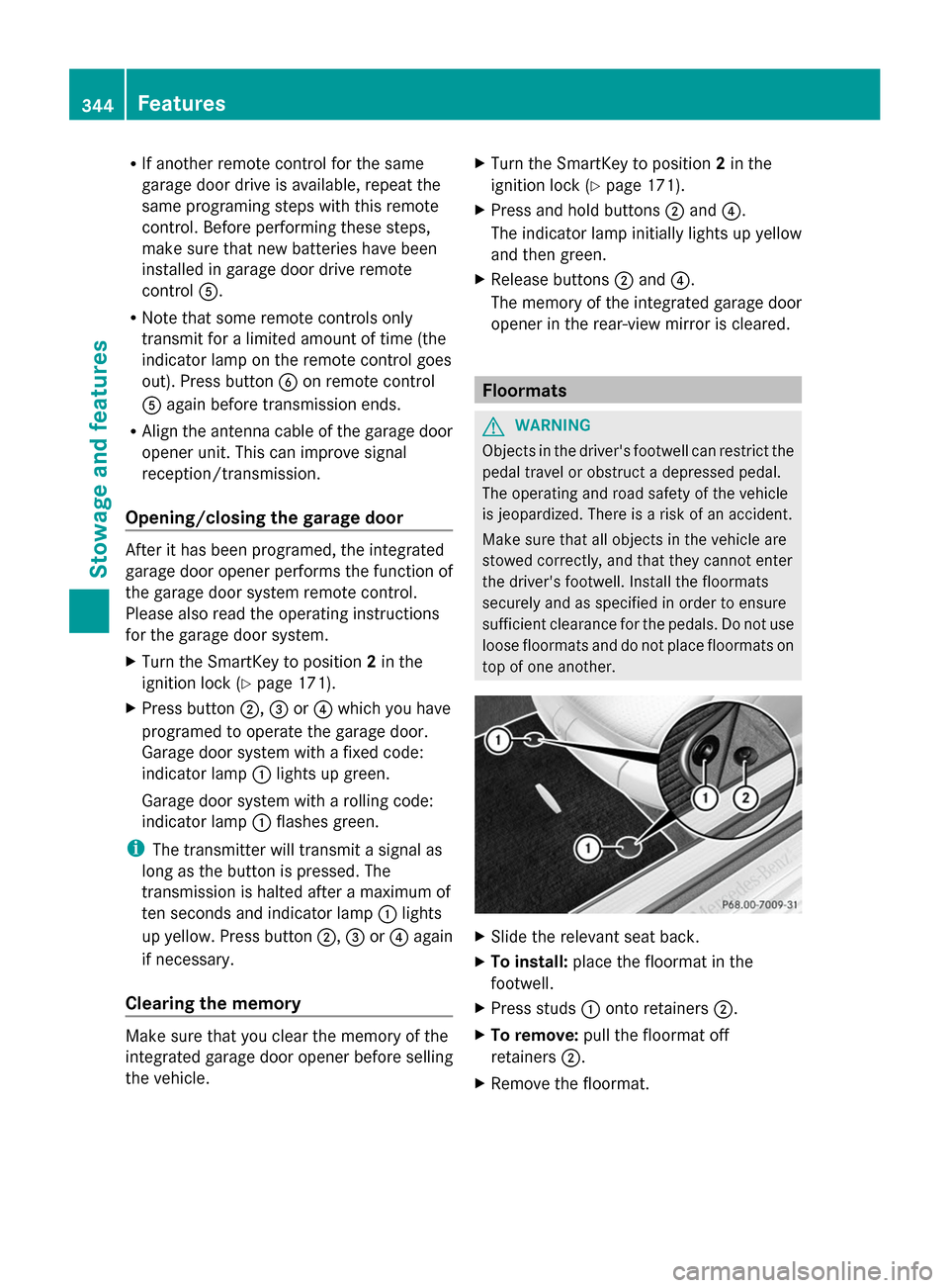
top of one another. X
Slide the relevant seat back.
X To install: place the floormat in the
footwell.
X Press studs 0043onto retainers 0044.
X To remove: pull the floormat off
retainers 0044.
X Remove the floormat. 344
FeaturesStowage and features