2014 MERCEDES-BENZ S-CLASS COUPE width
[x] Cancel search: widthPage 187 of 413
For safety reasons, Mercedes-Benz recom-
mends only fitting the following brake discs
and brake pads/linings:
R brake discs that have been approved by
Mercedes-Benz
R brake pads/linings that have been
approved by Mercedes-Benz or that are of
an equivalent standard of quality
Other brake discs or brake pads/linings can
compromise the safety of your vehicle.
Always replace all brake discs and brake
pads/linings on an axle at the same time.
Always fit new brake pads/linings when
replacing brake discs.
The vehicle is equipped with lightweight
brake discs to which the wheel assembly with
rim and threaded connection is matched.
The use of brake discs other than those
approved by Mercedes-Benz may alter track
width and is subject to approval, if applicable.
Shock-type loads when handling the brake
discs, such as when changing wheels, can
lead to a reduction in comfort when driving
with lightweight brake discs. Avoid shock-
type loads on the lightweight brake discs,
particularly on the brake plate.
AMG high-performance and ceramic
brakes The high-performance brake system is only
available on AMG vehicles.
The AMG brake systems are designed for
heavy loads. This may lead to noise when
braking. This is dependent on:
R speed
R braking force
R environmental conditions, such as temper-
ature and humidity
The wear of individual brake system compo-
nents such as the brake pads/linings or brake discs depends on individual driving style and
operating conditions.
For this reason, it is impossible to state a
mileage (service life) that will be valid under all circumstances. An aggressive driving style
will lead to high wear. You can obtain further information about this from your Mercedes-
Benz Service Centre.
Brake pads/linings and discs that are either
new or have been replaced only achieve opti- mum braking effect after several hundred kil-
ometres of driving. Compensate for the
reduced braking effect by applying greater
force to the brake pedal. Always be aware of
this and adapt your driving and braking
accordingly during the running-in period.
Excessive heavy braking results in corre-
spondingly high brake wear. Observe the
brake wear warning lamp in the instrument
cluster and note any brake status messages
in the multifunction display. If you regularly
drive at high speeds, it is particularly impor-
tant to have the brake system checked and
maintained regularly. Driving on wet roads
Aquaplaning If water has accumulated to a certain depth
on the road surface, there is a danger of aqua-
planing occurring, even if:
R you are driving at low speeds
R the tyres have adequate tread depth
For this reason, drive in the following manner in the event of heavy rain or in conditions in
which aquaplaning can occur:
R lower your speed
R avoid tyre ruts
R avoid sudden steering movements
R brake carefully
Driving on flooded roads !
Bear in mind that vehicles travelling in
front or in the opposite direction create
waves. This may cause the maximum per-
missible water depth to be exceeded.
These notes must be observed under all
circumstances. You could otherwise dam- 184
Driving tipsDriving and parking
Page 203 of 413
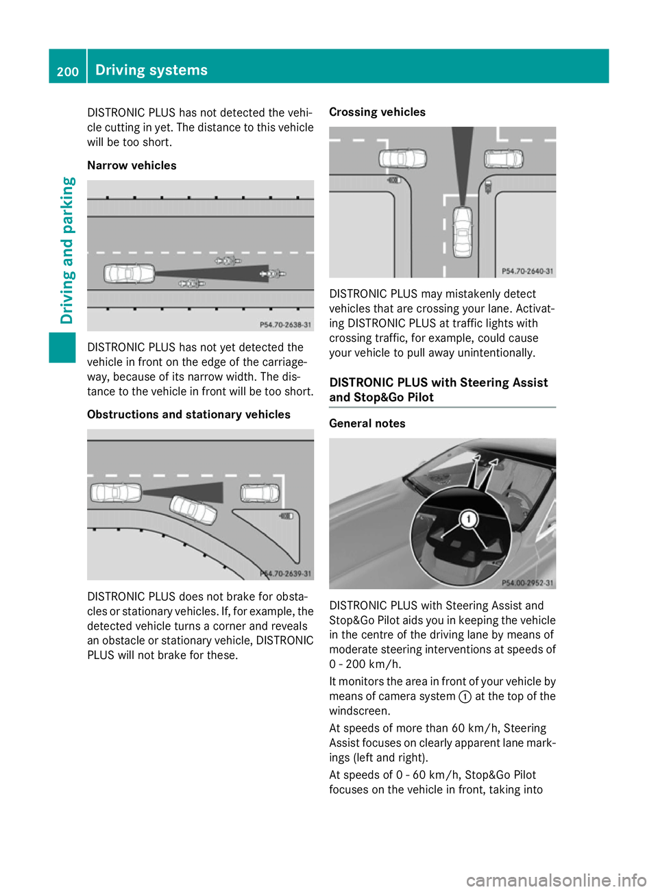
DISTRONIC PLUS has not detected the vehi-
cle cutting in yet. The distance to this vehicle will be too short.
Narrow vehicles DISTRONIC PLUS has not yet detected the
vehicle in front on the edge of the carriage-
way, because of its narrow width. The dis-
tance to the vehicle in front will be too short.
Obstructions and stationary vehicles DISTRONIC PLUS does not brake for obsta-
cles or stationary vehicles. If, for example, the
detected vehicle turns a corner and reveals
an obstacle or stationary vehicle, DISTRONIC PLUS will not brake for these. Crossing vehicles DISTRONIC PLUS may mistakenly detect
vehicles that are crossing your lane. Activat-
ing DISTRONIC PLUS at traffic lights with
crossing traffic, for example, could cause
your vehicle to pull away unintentionally.
DISTRONIC PLUS with Steering Assist
and Stop&Go Pilot General notes
DISTRONIC PLUS with Steering Assist and
Stop&Go Pilot aids you in keeping the vehicle in the centre of the driving lane by means of
moderate steering interventions at speeds of
0 - 200 km/h.
It monitors the area in front of your vehicle by means of camera system :at the top of the
windscreen.
At speeds of more than 60 km/h, Steering
Assist focuses on clearly apparent lane mark- ings (left and right).
At speeds of 0 - 60 km/h, Stop&Go Pilot
focuses on the vehicle in front, taking into 200
Driving systemsDriving an
d parking
Page 221 of 413

Activating/deactivating the reversing
camera X
To activate: make sure that the key is in
position 2in the ignition lock.
X Make sure that the Activation by R
Activation by R
gear
gear function is selected in COMAND
Online (see separate operating instruc-
tions).
X Engage reverse gear.
The reversing camera flap opens. The area
behind the vehicle is shown with guide lines in the COMAND display.
The image from the reversing camera is
available throughout the manoeuvring
process.
To deactivate: the reversing camera deacti-
vates if you shift the transmission to Por after
driving forwards a short distance.
Displays in the COMAND display The reversing camera may show a distorted
view of obstacles or show them incorrectly or not at all. Obstacles are not shown by the
reversing camera in the following locations:
R very close to the rear bumper
R under the rear bumper
R in the area immediately above the tailgate
handle
! Objects not at ground level may appear to
be further away than they actually are, e.g.:
R the bumper of a parked vehicle
R the drawbar of a trailer R
the ball coupling of a trailer tow hitch
R the rear section of an HGV
R a slanted post
Use the guidelines only for orientation.
Approach objects no further than the bot-
tom-most guideline. :
Yellow guide line at a distance of approx-
imately 4.0 mfrom the rear of the vehicle
; White guide line without turning the steer-
ing wheel, vehicle width including the
exterior mirrors (static)
= Yellow guide line for the vehicle width
including the exterior mirrors, for current
steering wheel angle (dynamic)
? Yellow lane marking the course the tyres
will take at the current steering wheel
angle (dynamic) A
Yellow guide line at a distance of approx-
imately 1.0 mfrom the rear of the vehicle
B Vehicle centre axis (locating aid)
C Bumper
D Red guide line at a distance of approx-
imately 0.30 mfrom the rear of the vehicle 218
Driving systemsDriving and parking
Page 222 of 413
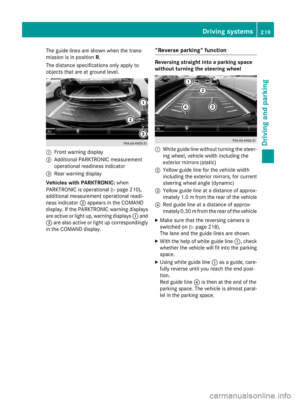
The guide lines are shown when the trans-
mission is in position R.
The distance specifications only apply to
objects that are at ground level. :
Front warning display
; Additional PARKTRONIC measurement
operational readiness indicator
= Rear warning display
Vehicles with PARKTRONIC: when
PARKTRONIC is operational (Y page 210),
additional measurement operational readi-
ness indicator ;appears in the COMAND
display. If the PARKTRONIC warning displays
are active or light up, warning displays :and
= are also active or light up correspondingly
in the COMAND display. "Reverse parking" function Reversing straight into a parking space
without turning the steering wheel
:
White guide line without turning the steer-
ing wheel, vehicle width including the
exterior mirrors (static)
; Yellow guide line for the vehicle width
including the exterior mirrors, for current
steering wheel angle (dynamic)
= Yellow guide line at a distance of approx-
imately 1.0 mfrom the rear of the vehicle
? Red guide line at a distance of approx-
imately 0.30 mfrom the rear of the vehicle
X Make sure that the reversing camera is
switched on (Y page 218).
The lane and the guide lines are shown.
X With the help of white guide line :, check
whether the vehicle will fit into the parking space.
X Using white guide line :as a guide, care-
fully reverse until you reach the end posi-
tion.
Red guide line ?is then at the end of the
parking space. The vehicle is almost paral-
lel in the parking space. Driving systems
219Driving and parking Z
Page 223 of 413
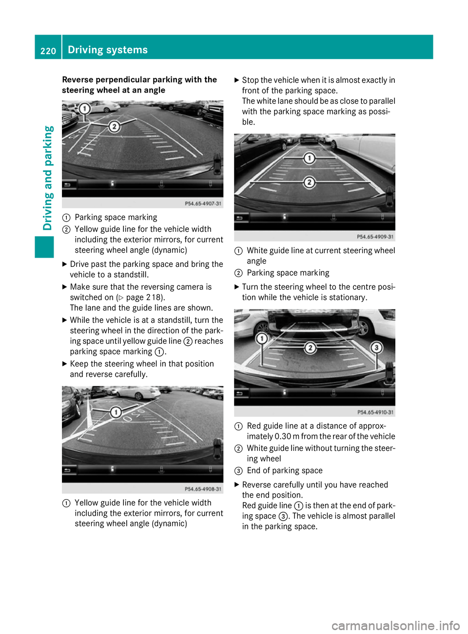
Reverse perpendicular parking with the
steering wheel at an angle :
Parking space marking
; Yellow guide line for the vehicle width
including the exterior mirrors, for current
steering wheel angle (dynamic)
X Drive past the parking space and bring the
vehicle to a standstill.
X Make sure that the reversing camera is
switched on (Y page 218).
The lane and the guide lines are shown.
X While the vehicle is at a standstill, turn the
steering wheel in the direction of the park-ing space until yellow guide line ;reaches
parking space marking :.
X Keep the steering wheel in that position
and reverse carefully. :
Yellow guide line for the vehicle width
including the exterior mirrors, for current
steering wheel angle (dynamic) X
Stop the vehicle when it is almost exactly in
front of the parking space.
The white lane should be as close to parallel
with the parking space marking as possi-
ble. :
White guide line at current steering wheel
angle
; Parking space marking
X Turn the steering wheel to the centre posi-
tion while the vehicle is stationary. :
Red guide line at a distance of approx-
imately 0.30 mfrom the rear of the vehicle
; White guide line without turning the steer-
ing wheel
= End of parking space
X Reverse carefully until you have reached
the end position.
Red guide line :is then at the end of park-
ing space =. The vehicle is almost parallel
in the parking space. 220
Driving systemsDriving and parking
Page 227 of 413
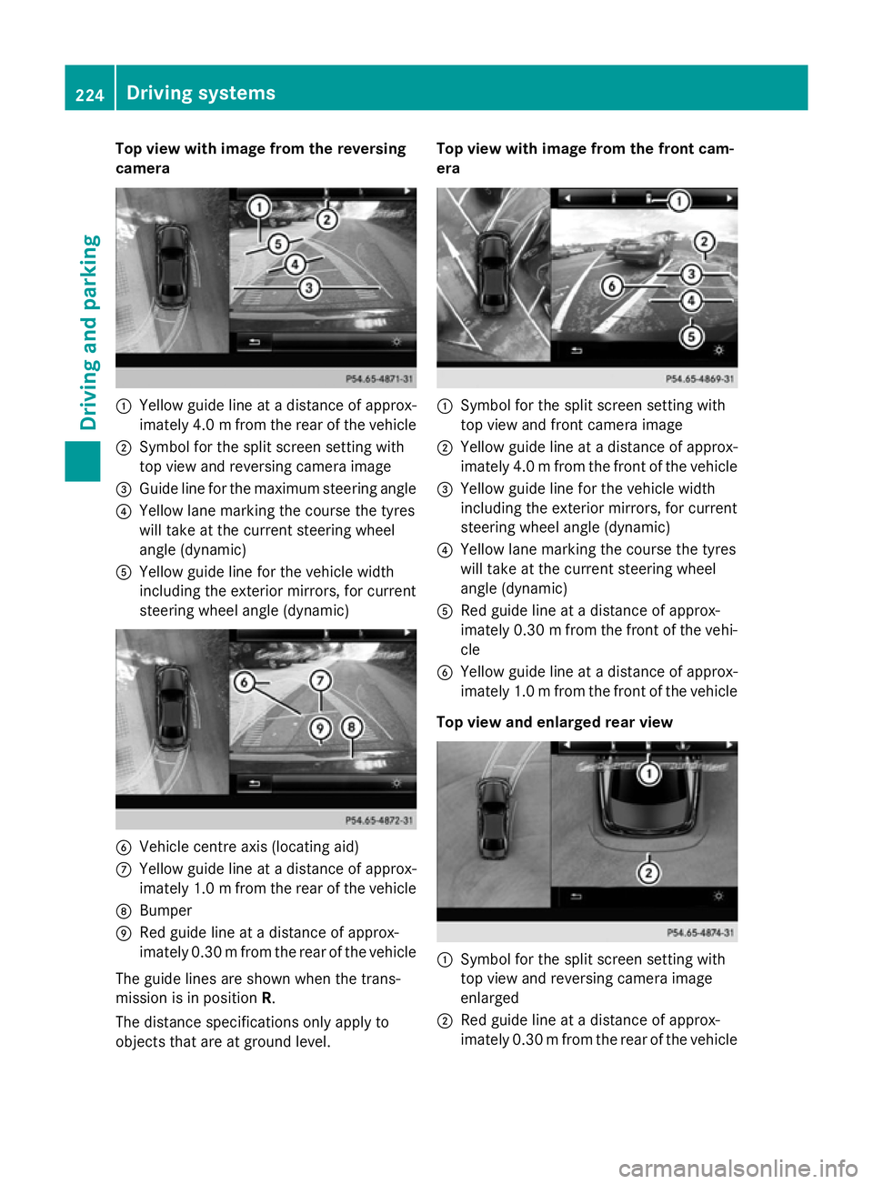
Top view with image from the reversing
camera :
Yellow guide line at a distance of approx-
imately 4.0 mfrom the rear of the vehicle
; Symbol for the split screen setting with
top view and reversing camera image
= Guide line for the maximum steering angle
? Yellow lane marking the course the tyres
will take at the current steering wheel
angle (dynamic)
A Yellow guide line for the vehicle width
including the exterior mirrors, for current
steering wheel angle (dynamic) B
Vehicle centre axis (locating aid)
C Yellow guide line at a distance of approx-
imately 1.0 mfrom the rear of the vehicle
D Bumper
E Red guide line at a distance of approx-
imately 0.30 mfrom the rear of the vehicle
The guide lines are shown when the trans-
mission is in position R.
The distance specifications only apply to
objects that are at ground level. Top view with image from the front cam-
era
:
Symbol for the split screen setting with
top view and front camera image
; Yellow guide line at a distance of approx-
imately 4.0 mfrom the front of the vehicle
= Yellow guide line for the vehicle width
including the exterior mirrors, for current
steering wheel angle (dynamic)
? Yellow lane marking the course the tyres
will take at the current steering wheel
angle (dynamic)
A Red guide line at a distance of approx-
imately 0.30 mfrom the front of the vehi-
cle
B Yellow guide line at a distance of approx-
imately 1.0 mfrom the front of the vehicle
Top view and enlarged rear view :
Symbol for the split screen setting with
top view and reversing camera image
enlarged
; Red guide line at a distance of approx-
imately 0.30 mfrom the rear of the vehicle 224
Driving systemsDriving and parking
Page 228 of 413
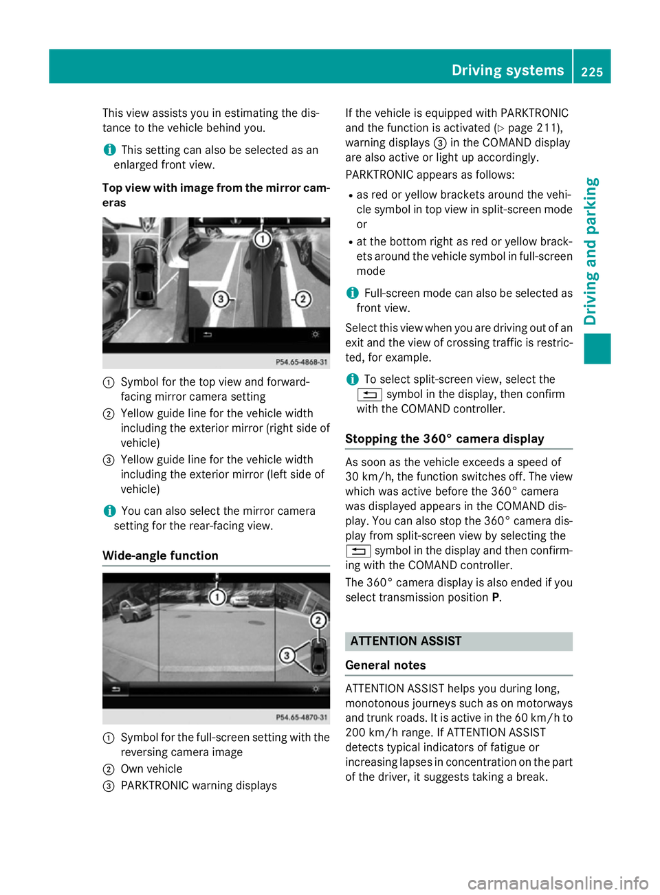
This view assists you in estimating the dis-
tance to the vehicle behind you.
i This setting can also be selected as an
enlarged front view.
Top view with image from the mirror cam- eras :
Symbol for the top view and forward-
facing mirror camera setting
; Yellow guide line for the vehicle width
including the exterior mirror (right side of
vehicle)
= Yellow guide line for the vehicle width
including the exterior mirror (left side of
vehicle)
i You can also select the mirror camera
setting for the rear-facing view.
Wide-angle function :
Symbol for the full-screen setting with the
reversing camera image
; Own vehicle
= PARKTRONIC warning displays If the vehicle is equipped with PARKTRONIC
and the function is activated (Y
page 211),
warning displays =in the COMAND display
are also active or light up accordingly.
PARKTRONIC appears as follows:
R as red or yellow brackets around the vehi-
cle symbol in top view in split-screen mode
or
R at the bottom right as red or yellow brack-
ets around the vehicle symbol in full-screen
mode
i Full-screen mode can also be selected as
front view.
Select this view when you are driving out of an exit and the view of crossing traffic is restric-
ted, for example.
i To select split-screen view, select the
% symbol in the display, then confirm
with the COMAND controller.
Stopping the 360° camera display As soon as the vehicle exceeds a speed of
30 km/h,
the function switches off. The view
which was active before the 360° camera
was displayed appears in the COMAND dis-
play. You can also stop the 360° camera dis-
play from split-screen view by selecting the
% symbol in the display and then confirm-
ing with the COMAND controller.
The 360° camera display is also ended if you
select transmission position P. ATTENTION ASSIST
General notes ATTENTION ASSIST helps you during long,
monotonous journeys such as on motorways
and trunk roads. It is active in the 60 km/h to
200 km/h range. If ATTENTION ASSIST
detects typical indicators of fatigue or
increasing lapses in concentration on the part
of the driver, it suggests taking a break. Driving systems
225Driving and parking Z
Page 380 of 413

as possible to check the wheels and tyres for
damage. Hidden tyre damage could also be
causing the unusual handling characteristics.
If you find no signs of damage, have the tyres and wheels checked at a qualified specialist
workshop.
When parking your vehicle, make sure that
the tyres do not get deformed by the kerb or
other obstacles. If it is necessary to drive over
kerbs, speed humps or similar elevations, try
to do so slowly and at an obtuse angle. Oth-
erwise, the tyres, particularly the sidewalls,
may be damaged. Regular checking of wheels and tyres
G
WARNING
Damaged tyres can cause tyre inflation pres-
sure loss. As a result, you could lose control of your vehicle. There is a risk of accident.
Check the tyres regularly for signs of damage and replace any damaged tyres immediately.
Regularly check the wheels and tyres of your
vehicle for damage at least once a month, as well as after driving off-road or on rough
roads. Damaged wheels can cause a loss of
tyre pressure. Pay particular attention to
damage such as:
R cuts in the tyres
R punctures
R tears in the tyres
R bulges on the tyres
R deformation or severe corrosion on wheels
Regularly check the tyre tread depth and the condition of the tread across the whole width
of the tyre (Y page 377). If necessary, turn
the front wheels to full lock in order to inspect
the inner side of the tyre surface.
All wheels must have a valve cap to protect
the valve against dirt and moisture. Do not fit
anything onto the valve other than the stand-
ard valve cap or other valve caps approved for
your vehicle by Mercedes-Benz. Do not fit any other valve caps or systems, e.g. tyre pres-
sure monitoring systems.
Regularly check the pressure of all the tyres,
particularly prior to long trips. Adjust the tyre
pressure as necessary (Y page 380).
The service life of tyres depends on various
factors, including the following:
R driving style
R tyre pressure
R mileage Important safety notes on the tyre
tread
G
WARNING
Insufficient tyre tread will reduce tyre trac-
tion. The tyre is no longer able to dissipate
water. This means that on wet road surfaces, the risk of aquaplaning increases, in particularwhere speed is not adapted to suit the driving
conditions. There is a risk of accident.
If the tyre pressure is too high or too low, tyres may exhibit different levels of wear at differ-
ent locations on the tyre tread. Thus, you
should regularly check the tread depth and
the condition of the tread across the entire
width of all tyres.
Minimum tyre tread depth for:
R summer tyres: 3 mm
R M+S tyres: 4 mm
For safety reasons, replace the tyres before
the legally prescribed limit for the minimum
tyre tread depth is reached. Selecting, fitting and replacing tyres
G
WARNING
Exceeding the stated tyre load-bearing capa-
city and the approved maximum speed could
lead to tyre damage or the tyre bursting. There is a risk of accident.
Therefore, only use tyre types and sizes
approved for your vehicle model. Observe the Operation
377Wheels and tyres
Z