2014 MERCEDES-BENZ S-CLASS COUPE fuel cap
[x] Cancel search: fuel capPage 14 of 413
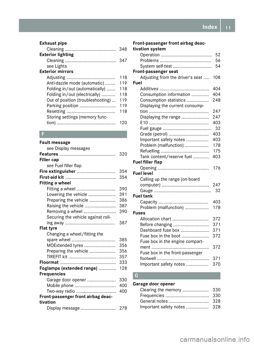
Exhaust pipe
Cleaning ........................................ .348
Exterior lighting
Cleaning ......................................... 347
see Lights
Exterior mirrors
Adjusting ....................................... 118
Anti-dazzle mode (automatic) ....... .119
Folding in/out (automatically) ....... 118
Folding in/out (electrically) ........... 118
Out of position (troubleshooting) ... 119
Parking position ............................. 119
Resetting ....................................... 118
Storing settings (memory func-
tion) ............................................... 120 F
Fault message see Display messages
Features ............................................. 320
Filler cap
see Fuel filler flap
Fire extinguisher ............................... 354
First-aid kit ......................................... 354
Fitting a wheel
Fitting a wheel ............................... 390
Lowering the vehicle ...................... 391
Preparing the vehicle ..................... 386
Raising the vehicl e......................... 387
Removing a whee l.......................... 390
Securing the vehicle against roll-
ing away ........................................ 387
Flat tyre
Changing a wheel/fitting the
spare whee l................................... 385
MOExtended tyre s......................... 356
Preparing the vehicle ..................... 356
TIREFIT kit ...................................... 357
Floormat ............................................. 333
Foglamps (extended range) .............. 128
Frequencies
Garage door opener ....................... 330
Mobile phone ................................. 400
Two-way radio ................................ 400
Front-passenger front airbag deac-
tivation
Display message ............................ 278 Front-passenger front airbag deac-
tivation system
Operation ......................................... 52
Problems ......................................... 56
System self-test ............................... 54
Front-passenger seat
Adjusting from the driver's seat ..... 108
Fuel
Additives ........................................ 404
Consumption information .............. 404
Consumption statistics .................. 248
Displaying the current consump-
tion ................................................ 247
Displaying the rang e...................... 247
E10 ................................................ 403
Fuel gaug e....................................... 32
Grade (petrol) ................................ 403
Important safety notes .................. 403
Problem (malfunction) ................... 178
Refuelling ....................................... 175
Tank content/reserve fue l............. 403
Fuel filler flap
Opening ......................................... 176
Fuel level
Calling up the range (on-board
computer) ...................................... 247
Gaug e.............................................. 32
Fuel tank
Capacity ........................................ 403
Problem (malfunction) ................... 178
Fuses
Allocation chart ............................. 372
Before changing ............................. 371
Dashboard fuse box ....................... 371
Fuse box in the boot ...................... 372
Fuse box in the engine compart-
ment .............................................. 372
Fuse box in the front-passenger
footwell .......................................... 371
Important safety notes .................. 370 G
Garage door opener Clearing the memory ..................... 330
Frequencies ................................... 330
General notes ................................ 328
Important safety notes .................. 328 Index
11
Page 97 of 413
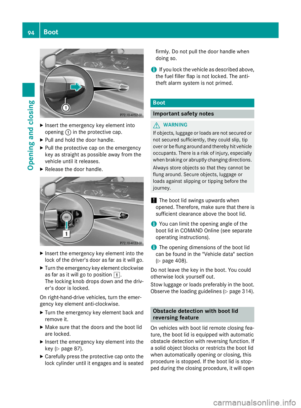
X
Insert the emergency key element into
opening :in the protective cap.
X Pull and hold the door handle.
X Pull the protective cap on the emergency
key as straight as possible away from the
vehicle until it releases.
X Release the door handle. X
Insert the emergency key element into the
lock of the driver's door as far as it will go.
X Turn the emergency key element clockwise
as far as it will go to position 1.
The locking knob drops down and the driv- er's door is locked.
On right-hand-drive vehicles, turn the emer-
gency key element anti-clockwise.
X Turn the emergency key element back and
remove it.
X Make sure that the doors and the boot lid
are locked.
X Insert the emergency key element into the
key (Y page 87).
X Carefully press the protective cap onto the
lock cylinder until it engages and is seated firmly. Do not pull the door handle when
doing so.
i If you lock the vehicle as described above,
the fuel filler flap is not locked. The anti-
theft alarm system is not primed. Boot
Important safety notes
G
WARNING
If objects, luggage or loads are not secured or not secured sufficiently, they could slip, tip
over or be flung around and thereby hit vehicle
occupants. There is a risk of injury, especially when braking or abruptly changing directions.
Always store objects so that they cannot be
flung around. Secure objects, luggage or
loads against slipping or tipping before the
journey.
! The boot lid swings upwards when
opened. Therefore, make sure that there is sufficient clearance above the boot lid.
i You can limit the opening angle of the
boot lid in COMAND Online (see separate
operating instructions).
i The opening dimensions of the boot lid
can be found in the "Vehicle data" section
(Y page 408).
Do not leave the key in the boot. You could
otherwise lock yourself out.
Stow luggage or loads preferably in the boot.
Observe the loading guidelines (Y page 314). Obstacle detection with boot lid
reversing feature
On vehicles with boot lid remote closing fea-
ture, the boot lid is equipped with automatic
obstacle detection with reversing function. If
a solid object blocks or restricts the boot lid
when automatically opening or closing, this
procedure is stopped. If the boot lid is stop-
ped during the closing procedure, it will open 94
BootOpening and closing
Page 152 of 413
When the auxiliary heating is switched on,
make sure that:
R no flammable materials come into contact
with hot vehicle components
R the exhaust gas can escape from the
exhaust pipe unhindered
R the exhaust gas does not come into contact
with flammable materials.
The auxiliary heating and the exhaust gas out-
let are situated behind the right-hand front
wheel.
! Operating the auxiliary heating/ventila-
tion draws on the vehicle battery. After you
have heated or ventilated the vehicle a
maximum of two times, drive for a longer
distance.
Switch the auxiliary heating on regularly once
a month for about ten minutes.
The auxiliary heating heats the air in the vehi-
cle interior to the set temperature. This
occurs without using the heat of the running
engine. The auxiliary heating is operated
directly using the vehicle's fuel. For this rea-
son, the tank content must be at least at
reserve fuel level to ensure that the auxiliary
heating functions.
The auxiliary heating/ventilation automati-
cally adjusts to changes in temperature and
weather conditions. For this reason, the aux- iliary heating could switch from ventilation
mode to heating mode or from heating mode to ventilation mode.
The auxiliary heating switches off when the
engine is switched off. The auxiliary ventila-
tion switches off when you turn the key to key
position 2(Y page 159).
The auxiliary heating switches off automati-
cally after 30 minutes. This time limit can be
altered. To do this, visit a qualified specialist
workshop.
You cannot use the auxiliary ventilation to
cool the vehicle interior to a temperature
lower than the outside temperature. Before switching on X
Turn the key to position 2in the ignition
lock (Y page 159).
X Set the desired temperature using the
w rocker switch on the front control unit
or using COMAND Online (see the separate operating instructions).
If you do not alter the temperature before
switching on the auxiliary heating, the last
temperature setting will be adopted.
Auxiliary heating or ventilation can also be
switched on if the manually set climate con-
trol is activated. Optimum comfort can be
attained when the system is set to automatic
mode. Set the temperature to 22 †.
You can activate or deactivate the auxiliary
heating/ventilation:
R using the rocker switch on the centre con-
sole (Y page 149)
R using the remote control (Y page 150)
The on-board computer can be used to spec- ify up to three departure times, one of which
may be preselected:
R using the remote control (Y page 150)
R using COMAND Online (see the separate
operating instructions)
Switching the auxiliary heating/venti-
lation on/off using the centre console
rocker switch The colours of the indicator lamps on the
rocker switch have the following meanings:
Blue Auxiliary ventilation switched on
Red Auxiliary heating switched on
Yellow Departure time preselected Operating the climate control system
149Climate control Z
Page 155 of 413
X
Press the uand^ buttons simulta-
neously.
The Îsymbol in the remote control dis-
play flashes.
X Press the ,or. button to set the
desired departure time.
i The longer you press the
,or.
button, the faster the time changes.
X Press the uand^ buttons simulta-
neously.
The new departure time is stored.
When setting the departure time, observe the important safety notes (Y page 148).
Activating the set departure time X Briefly press the ubutton.
X Press the ,or. button repeatedly
until the desired departure time appears in
the display.
X Press the ubutton.
The Ísymbol, the departure time and,
depending on the selected departure time, the letter A, BorCappear in the display.
Deactivating the set departure time
X Briefly press the ubutton.
X Press the ,or. button.
The status of the auxiliary heating is shown in the display.
X Press the .button.
The first departure time stored appears in
the display.
X Press the ^button.
OFF
OFF is shown in the remote control display.
Switching the heater booster function
on/off The heater booster function helps the engine
reach its operating temperature faster during
its warm-up phase. This helps to heat the
vehicle interior faster. The heater booster
function switches on at lower outside tem-
peratures and lower coolant temperatures.
You can also activate the heater booster man- ually. X
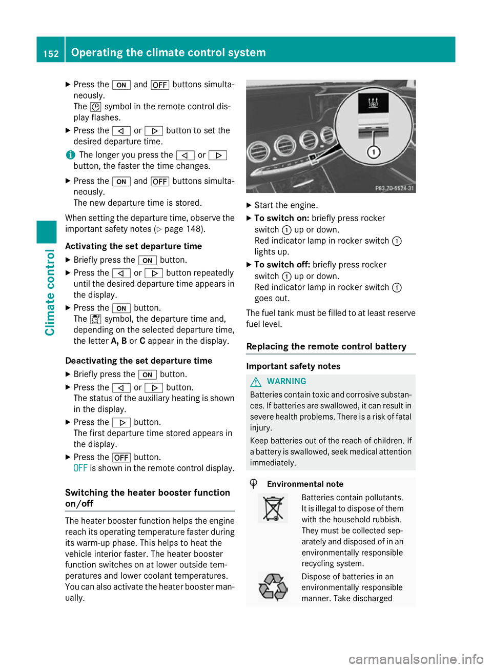
Start the engine.
X To switch on: briefly press rocker
switch :up or down.
Red indicator lamp in rocker switch :
lights up.
X To switch off: briefly press rocker
switch :up or down.
Red indicator lamp in rocker switch :
goes out.
The fuel tank must be filled to at least reserve fuel level.
Replacing the remote control battery Important safety notes
G
WARNING
Batteries contain toxic and corrosive substan- ces. If batteries are swallowed, it can result in
severe health problems. There is a risk of fatal injury.
Keep batteries out of the reach of children. If
a battery is swallowed, seek medical attention immediately. H
Environmental note Batteries contain pollutants.
It is illegal to dispose of them
with the household rubbish.
They must be collected sep-
arately and disposed of in anenvironmentally responsible
recycling system. Dispose of batteries in an
environmentally responsible
manner. Take discharged152
Operating the climate control systemClimate control
Page 179 of 413
If you or others come into contact with fuel,
observe the following:
R Wash the fuel off any affected areas of skin
with water and soap immediately.
R If you get fuel in your eyes, rinse them thor-
oughly with clean water immediately. Seek
immediate medical attention.
R If fuel is swallowed, seek immediate medi-
cal attention. Do not induce vomiting.
R Change any clothing that has come into
contact with fuel immediately. G
WARNING
Electrostatic charge can cause sparks and
thereby ignite fuel vapours. There is a risk of
fire and explosion.
Always touch the vehicle body before opening the fuel filler flap or touching the fuel pump
nozzle. This discharges any electrostatic
charge that may have built up.
Do not get into the vehicle again during the
refuelling process. Otherwise, electrostatic
charge could build up again.
! Do not use diesel to refuel vehicles with a
petrol engine. Do not switch on the ignition if you accidentally refuel with the wrong
fuel. Otherwise, fuel can enter the fuel sys- tem. Even small amounts of the wrong fuel could result in damage to the fuel system
and the engine. Notify a qualified specialist
workshop and have the fuel tank and fuel
lines drained completely.
! Overfilling the fuel tank could damage the
fuel system.
! Take care not to spill any fuel on painted
surfaces. You could otherwise damage the
paintwork.
! Use a filter when adding fuel from a fuel
can. The fuel lines and/or the diesel injec-
tion system could otherwise be blocked by particles from the fuel can. If you overfill the fuel tank, some fuel may
spray out when you remove the fuel pump
nozzle.
For further information on fuel and fuel quality (Y page 403). Refuelling
General notes Observe the important safety notes
(Y
page 175).
If you unlock/lock the vehicle from the out-
side, the fuel filler flap also unlocks/locks.
The position of the 8fuel filler cap is dis-
played in the instrument cluster. The arrow
next to the filling pump indicates the side of
the vehicle.
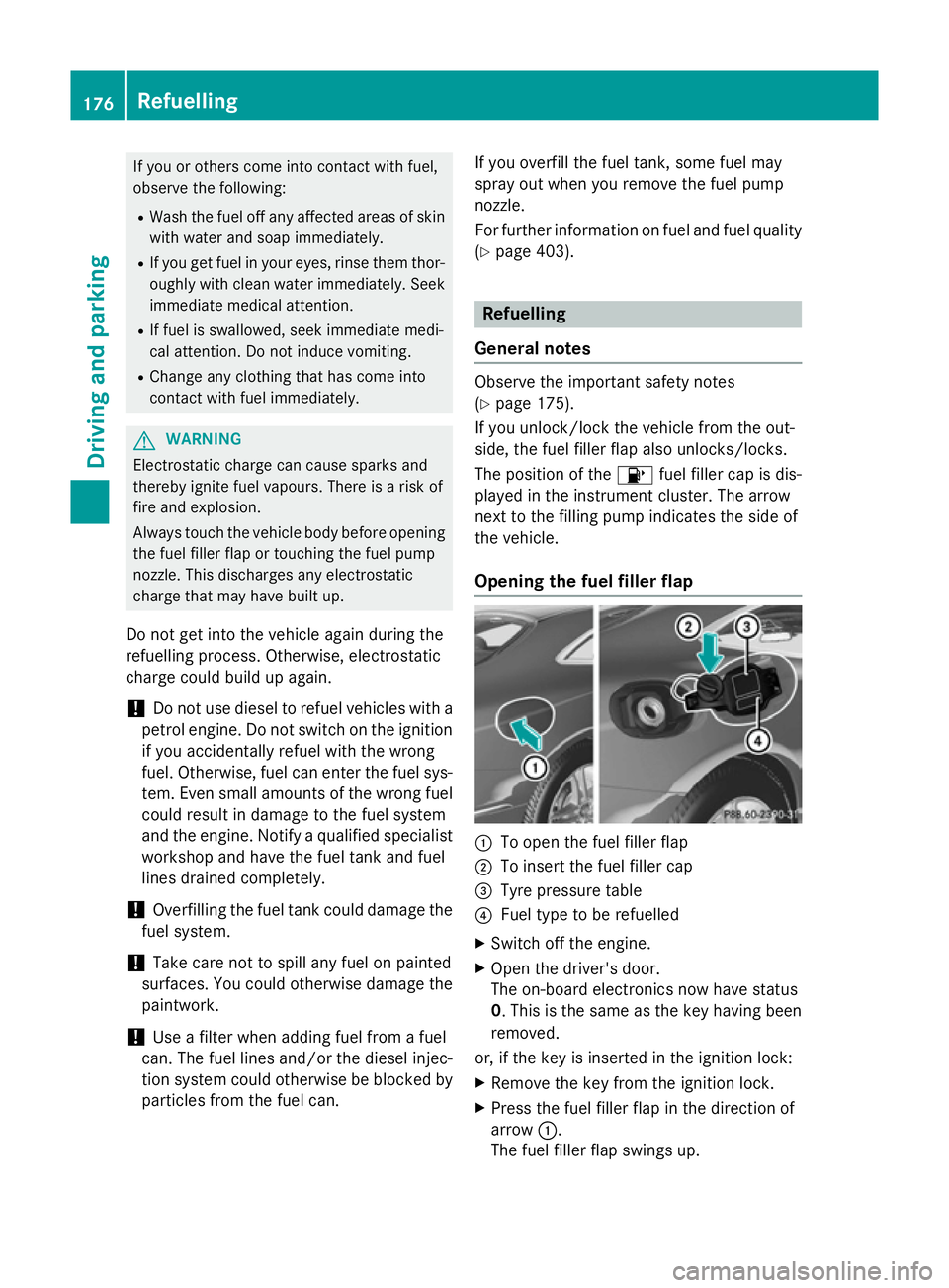
Opening the fuel filler flap :
To open the fuel filler flap
; To insert the fuel filler cap
= Tyre pressure table
? Fuel type to be refuelled
X Switch off the engine.
X Open the driver's door.
The on-board electronics now have status
0. This is the same as the key having been
removed.
or, if the key is inserted in the ignition lock:
X Remove the key from the ignition lock.
X Press the fuel filler flap in the direction of
arrow :.
The fuel filler flap swings up. 176
RefuellingDriving and parking
Page 180 of 413
X
Turn the fuel filler cap anti-clockwise and
remove it.
X Insert the fuel filler cap into the holder on
the inside of fuel filler flap ;.
X Completely insert the filler neck of the fuel
pump nozzle into the tank, hook in place
and refuel.
X Only fill the tank until the pump nozzle
switches off.
i Do not add any more fuel after the pump
stops filling for the first time. Otherwise,
fuel may leak out.
Closing the fuel filler flap X
Replace the cap on the filler neck and turn
clockwise until it engages audibly.
X Close the fuel filler flap.
i Close the fuel filler flap before locking the
vehicle. Refuelling
177Driving and parking Z
Page 363 of 413

and a tyre pressure that is too low can signif-
icantly impair the vehicle's braking and driv-
ing characteristics. There is a risk of accident.
Do not continue driving. Contact a qualified
specialist workshop.
i In your vehicle, you will find a sticker with
the Mercedes-Benz Service24h telephone
number, e.g. on the B-pillar on the driver's
side.
X Correct the tyre pressure if it is still at least
130 kPa (1.3 bar/19 psi). See the tyre
pressure table in the fuel filler flap for val-
ues.
X To increase the tyre pressure: switch on
the tyre inflation compressor. X
To reduce the tyre pressure: depress
pressure release button Enext to pres-
sure gauge F.
X When the tyre pressure is correct, unscrew
the filler hose from the valve of the sealed
tyre.
X Screw the valve cap onto the tyre valve of
the sealed tyre.
X Pull the tyre sealant bottle out of the tyre
inflation compressor.
The filler hose stays on the tyre sealant
bottle.
X Stow the tyre sealant bottle, the tyre infla-
tion compressor and the warning triangle.
X Drive to the nearest qualified specialist
workshop and have the tyre changed there. X
Have the tyre sealant bottle replaced as
soon as possible at a qualified specialist
workshop.
X Have the tyre sealant bottle replaced every
four years at a qualified specialist work-
shop. Battery (vehicle)
Important safety notes
Work on the battery, e.g. removing or fitting,
requires specialist knowledge and the use of
special tools. Therefore, always have work on the battery carried out at a qualified specialist
workshop. G
WARNING
Work carried out incorrectly on the battery
may lead to a malfunction, e.g. a short circuit. This, in turn, may restrict the functions of the
safety-relevant systems, e.g. the lighting sys-
tem, ABS (Anti-lock Braking System) or ESP ®
(Electronic Stability Program). The operating
safety of your vehicle may then be compro-
mised. You could then lose control of the vehi-
cle, e.g.:
R when braking
R when making sudden steering movements
and/or travelling at an inappropriate
speed.
There is a risk of an accident.
In the event of a short circuit or similar situa-
tion, inform a qualified specialist workshop
immediately. Do not drive any further. You
should have all work involving the battery car- ried out at a qualified specialist workshop.
i For further information about ABS and
ESP ®
, see (Y page 70) and (Y page 75). G
WARNING
Electrostatic build-up can lead to the creation of sparks, which could ignite the highly explo-
sive gases of a battery. There is a risk of an
explosion. 360
Battery (vehicle)Breakdown assistance
Page 367 of 413
Jump-starting
For the jump-starting procedure, use only the jump-starting connection point, consisting of a positive terminal and an earth point, in the engine compartment. G
WARNING
Battery acid is caustic. There is a risk of injury.
Avoid contact with the skin, eyes or clothing. Do not inhale any battery gases. Do not lean over the battery. Keep children away from batteries. Wash battery acid immediately with water and seek
medical attention. G
WARNING
During charging and jump-starting, explosive gases can escape from the battery. There is a risk of an explosion.
Particularly avoid fire, naked flames, creating sparks and smoking. Ensure there is sufficient
ventilation while charging and jump-starting. Do not lean over a battery. G
WARNING
During the charging process, a battery produces hydrogen gas. If a short circuit occurs or sparks
are created, the hydrogen gas can ignite. There is a risk of an explosion.
R Make sure that the positive terminal of a connected battery does not come into contact with
vehicle parts.
R Never place metal objects or tools on a battery.
R It is important that you observe the described order of the battery terminals when connecting
and disconnecting a battery.
R When jump-starting, make sure that the battery poles with identical polarity are connected.
R It is particularly important to observe the described order when connecting and disconnecting
the jump leads.
R Never connect or disconnect the battery terminals while the engine is running. G
WARNING
A discharged battery can freeze at temperatures below freezing point. When jump-starting the
vehicle or charging the battery, gases can escape from the battery. There is a risk of an explosion.
Allow the frozen battery to thaw out before charging it or jump-starting.
! Avoid repeated and lengthy starting attempts. Otherwise, the catalytic converter could be
damaged by the non-combusted fuel.
If the indicator/warning lamps do not light up at low temperatures, it is very likely that the
discharged battery has frozen. In this case you may neither jump-start the vehicle nor charge
the battery. The service life of a battery that has been thawed may be reduced. The starting
characteristics may be impaired, especially at low temperatures. Have the thawed battery
checked at a qualified specialist workshop. 364
Jump-startingBreakdown assistance