2014 MERCEDES-BENZ S-CLASS COUPE towing
[x] Cancel search: towingPage 322 of 413
X
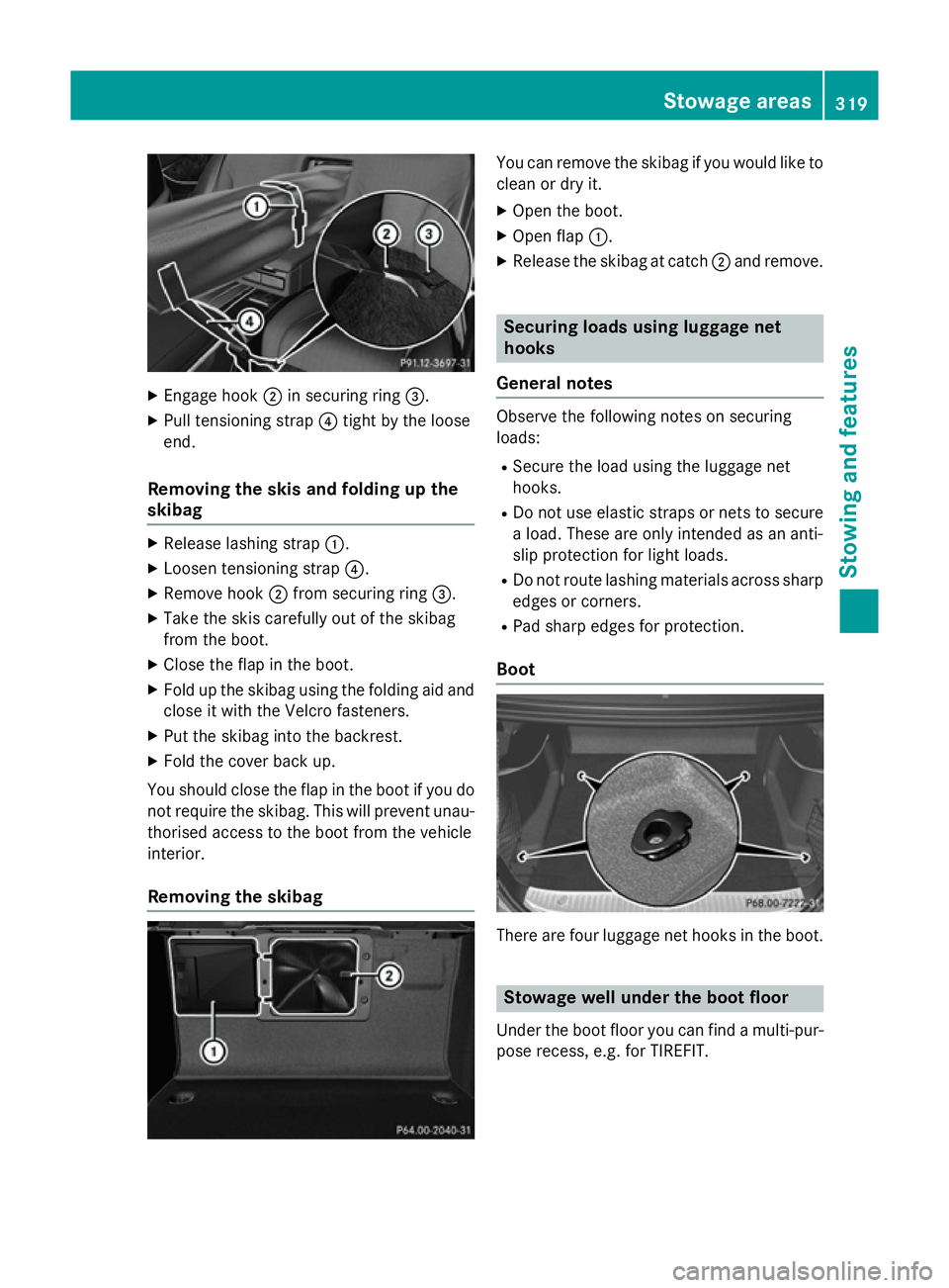
Engage hook ;in securing ring =.
X Pull tensioning strap ?tight by the loose
end.
Removing the skis and folding up the
skibag X
Release lashing strap :.
X Loosen tensioning strap ?.
X Remove hook ;from securing ring =.
X Take the skis carefully out of the skibag
from the boot.
X Close the flap in the boot.
X Fold up the skibag using the folding aid and
close it with the Velcro fasteners.
X Put the skibag into the backrest.
X Fold the cover back up.
You should close the flap in the boot if you do not require the skibag. This will prevent unau-
thorised access to the boot from the vehicle
interior.
Removing the skibag You can remove the skibag if you would like to
clean or dry it.
X Open the boot.
X Open flap :.
X Release the skibag at catch ;and remove. Securing loads using luggage net
hooks
General notes Observe the following notes on securing
loads:
R Secure the load using the luggage net
hooks.
R Do not use elastic straps or nets to secure
a load. These are only intended as an anti-
slip protection for light loads.
R Do not route lashing materials across sharp
edges or corners.
R Pad sharp edges for protection.
Boot There are four luggage net hooks in the boot.
Stowage well under the boot floor
Under the boot floor you can find a multi-pur-
pose recess, e.g. for TIREFIT. Sto
wage areas
319Stowing and features Z
Page 324 of 413
X
To open: open the stowage compartment
(Y page 315).
X To remove: slide catch:forwards and
pull the cup holder upwards.
X To insert: make sure that the head unit
cover is closed.
X Insert the cup holder and slide catch :
back.
You can remove the cup holder and the rub-
ber mat for cleaning. Clean them with clean,
lukewarm water only.
Cup holder in the rear seat armrest !
Do not sit on or support your body weight
on the rear seat armrest when it is folded
down, as you could otherwise damage it.
! Close the cup holder before folding the
rear seat armrest up. Otherwise, the cup
holder could be damaged. X
Fold down the rear seat armrest.
X To open: press the front of cup holder :
or ;.
Cup holder :or; extends automatically.
X To fold out: place a container in the cup
holder.
The cup holder folds down automatically.
X To fold in: remove the container.
The cup holder folds in automatically.
X To close: slide cup holder :or; back
until it engages. Sun visors
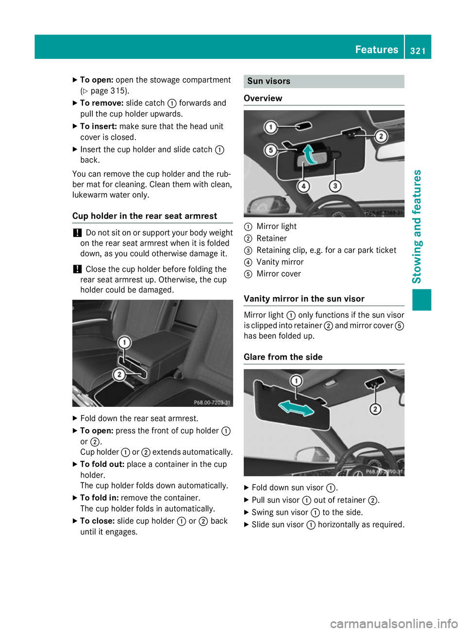
Overview :
Mirror light
; Retainer
= Retaining clip, e.g. for a car park ticket
? Vanity mirror
A Mirror cover
Vanity mirror in the sun visor Mirror light
:only functions if the sun visor
is clipped into retainer ;and mirror cover A
has been folded up.
Glare from the side X
Fold down sun visor :.
X Pull sun visor :out of retainer ;.
X Swing sun visor :to the side.
X Slide sun visor :horizontally as required. Features
321Stowing an d features Z
Page 325 of 413
Rear window roller sunblind
Important safety notes G
WARNING
Parts of the body could be trapped in the
sweep of the roller sunblind when the roller
sunblind is extended or retracted. There is a
risk of injury.
When extending or retracting make sure that
no parts of the body are in the sweep of the
roller sunblind. Briefly press the button again if someone becomes trapped. The opening/
closing process is stopped.
! Make sure that the roller sunblind can
move freely. Otherwise, the roller sunblind
or other objects could be damaged.
At temperatures below Ò20 † the roller sun-
blind cannot be operated.
Extending/retracting from the driver's
seat X
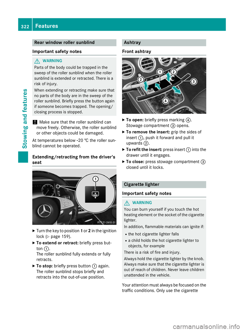
Turn the key to position 1or 2in the ignition
lock (Y page 159).
X To extend or retract: briefly press but-
ton :.
The roller sunblind fully extends or fully
retracts.
X To stop: briefly press button :again.
The roller sunblind stops briefly and
retracts into the out-of-use position. Ashtray
Front ashtray X
To open: briefly press marking ?.
Stowage compartment =opens.
X To remove the insert: grip the sides of
insert :, push it forward and pull it
upwards ;.
X To refit the insert: press insert:into the
drawer until it engages.
X To close: press stowage compartment =
closed until it locks. Cigarette lighter
Important safety notes G
WARNING
You can burn yourself if you touch the hot
heating element or the socket of the cigarette lighter.
In addition, flammable materials can ignite if:
R the hot cigarette lighter falls
R a child holds the hot cigarette lighter to
objects, for example
There is a risk of fire and injury.
Always hold the cigarette lighter by the knob.
Always make sure that the cigarette lighter is
out of reach of children. Never leave children unattended in the vehicle.
Your attention must always be focused on the traffic conditions. Only use the cigarette 322
FeaturesStowing and features
Page 326 of 413
lighter when road and traffic conditions per-
mit.
Cigarette lighter in the front compart-
ment X
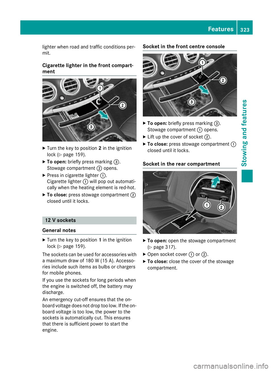
Turn the key to position 2in the ignition
lock (Y page 159).
X To open: briefly press marking =.
Stowage compartment ;opens.
X Press in cigarette lighter :.
Cigarette lighter :will pop out automati-
cally when the heating element is red-hot.
X To close: press stowage compartment ;
closed until it locks. 12 V sockets
General notes X
Turn the key to position 1in the ignition
lock (Y page 159).
The sockets can be used for accessories with a maximum draw of 180 W (15A). Accesso-
ries include such items as bulbs or chargers
for mobile phones.
If you use the sockets for long periods when
the engine is switched off, the battery may
discharge.
An emergency cut-off ensures that the on-
board voltage does not drop too low. If the on-
board voltage is too low, the power to the
sockets is automatically cut. This ensures
that there is sufficient power to start the
engine. Socket in the front cent
re console X
To open: briefly press marking =.
Stowage compartment :opens.
X Lift up the cover of socket ;.
X To close: press stowage compartment :
closed until it locks.
Socket in the rear compartment X
To open: open the stowage compartment
(Y page 317).
X Open socket cover :or;.
X To close: close the cover of the stowage
compartment. Features
323Stowing an d features Z
Page 327 of 413
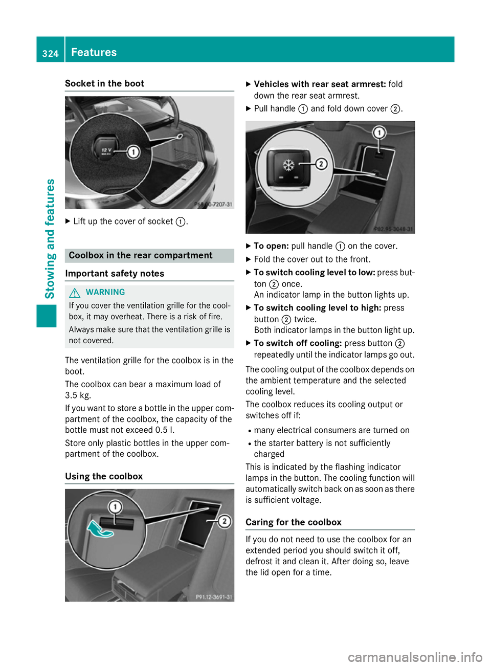
Socket in the boot
X
Lift up the cover of socket :.Coolbox in the rear compartment
Important safety notes G
WARNING
If you cover the ventilation grille for the cool-
box, it may overheat. There is a risk of fire.
Always make sure that the ventilation grille is not covered.
The ventilation grille for the coolbox is in the
boot.
The coolbox can bear a maximum load of
3.5 kg.
If you want to store a bottle in the upper com-
partment of the coolbox, the capacity of the
bottle must not exceed 0.5 l.
Store only plastic bottles in the upper com-
partment of the coolbox.
Using the coolbox X
Vehicles with rear seat armrest: fold
down the rear seat armrest.
X Pull handle :and fold down cover ;. X
To open: pull handle :on the cover.
X Fold the cover out to the front.
X To switch cooling level to low: press but-
ton ;once.
An indicator lamp in the button lights up.
X To switch cooling level to high: press
button ;twice.
Both indicator lamps in the button light up.
X To switch off cooling: press button;
repeatedly until the indicator lamps go out.
The cooling output of the coolbox depends on
the ambient temperature and the selected
cooling level.
The coolbox reduces its cooling output or
switches off if:
R many electrical consumers are turned on
R the starter battery is not sufficiently
charged
This is indicated by the flashing indicator
lamps in the button. The cooling function will automatically switch back on as soon as there
is sufficient voltage.
Caring for the coolbox If you do not need to use the coolbox for an
extended period you should switch it off,
defrost it and clean it. After doing so, leave
the lid open for a time.324
FeaturesStowing and features
Page 328 of 413
Removing and fitting the coolbox
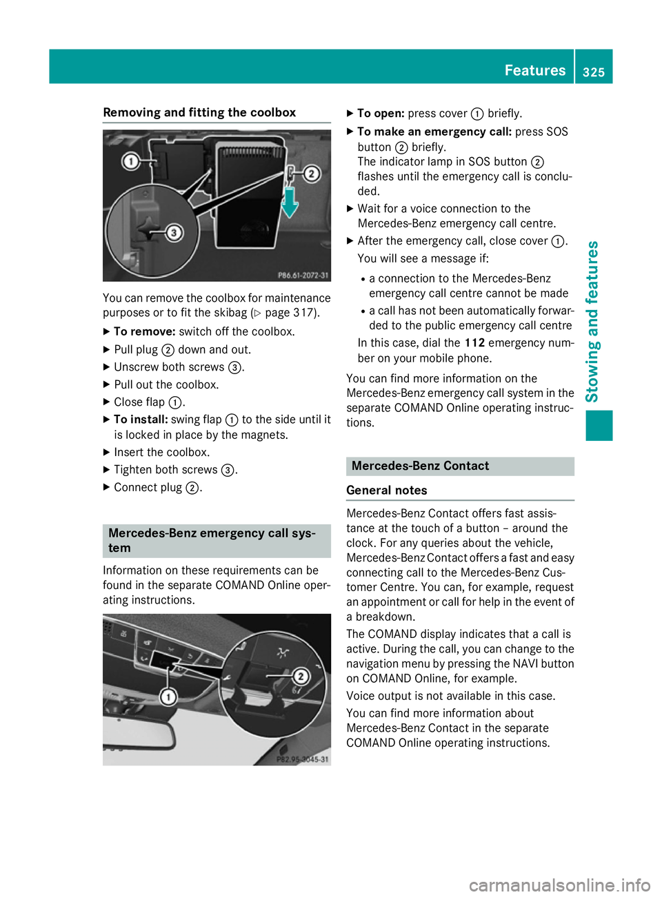
You can remove the coolbox for maintenance
purposes or to fit the skibag (Y page 317).
X To remove: switch off the coolbox.
X Pull plug ;down and out.
X Unscrew both screws =.
X Pull out the coolbox.
X Close flap :.
X To install: swing flap:to the side until it
is locked in place by the magnets.
X Insert the coolbox.
X Tighten both screws =.
X Connect plug ;. Mercedes-Benz emergency call sys-
tem
Information on these requirements can be
found in the separate COMAND Online oper-
ating instructions. X
To open: press cover :briefly.
X To make an emergency call: press SOS
button ;briefly.
The indicator lamp in SOS button ;
flashes until the emergency call is conclu-
ded.
X Wait for a voice connection to the
Mercedes-Benz emergency call centre.
X After the emergency call, close cover :.
You will see a message if:
R a connection to the Mercedes-Benz
emergency call centre cannot be made
R a call has not been automatically forwar-
ded to the public emergency call centre
In this case, dial the 112emergency num-
ber on your mobile phone.
You can find more information on the
Mercedes-Benz emergency call system in the separate COMAND Online operating instruc-
tions. Mercedes-Benz Contact
General notes Mercedes-Benz Contact offers fast assis-
tance at the touch of a button – around the
clock. For any queries about the vehicle,
Mercedes-Benz Contact offers a fast and easy
connecting call to the Mercedes-Benz Cus-
tomer Centre. You can, for example, request
an appointment or call for help in the event of a breakdown.
The COMAND display indicates that a call is
active. During the call, you can change to the
navigation menu by pressing the NAVI button
on COMAND Online, for example.
Voice output is not available in this case.
You can find more information about
Mercedes-Benz Contact in the separate
COMAND Online operating instructions. Features
325Stowing and features Z
Page 330 of 413
sion surrounding the possible health risk
posed by electromagnetic fields.
Mercedes-Benz recommends the use of an
approved exterior aerial. This ensures:
R optimal mobile phone reception quality in
the vehicle
R that mutual interference between the vehi-
cle electronics and mobile phones is mini-
mised
An exterior aerial has the following advan-
tages:
R it conducts the electromagnetic fields gen-
erated by a wireless device to the exterior
R the field strength in the vehicle interior is
lower than in a vehicle that does not have
an exterior aerial
Information on retrofitting two-way radios
and mobile phones (RF transmitters)
(Y page 400).
General notes Depending on the vehicle equipment, there
are various mobile phone brackets that may
be fitted in your vehicle; in some cases, these
are country-specific.
More information on suitable mobile phones,
mobile phone brackets and on connecting
Bluetooth ®
-capable mobile phones with
COMAND Online can be obtained:
R at your Mercedes-Benz Service Centre
R on the Internet at http://www.mercedes-
benz.com/connect
The functions and services available when
you use the phone depend on your mobile
phone model and service provider.
Using a mobile phone To connect a mobile phone to the exterior
aerial and charge it, insert it into the mobile
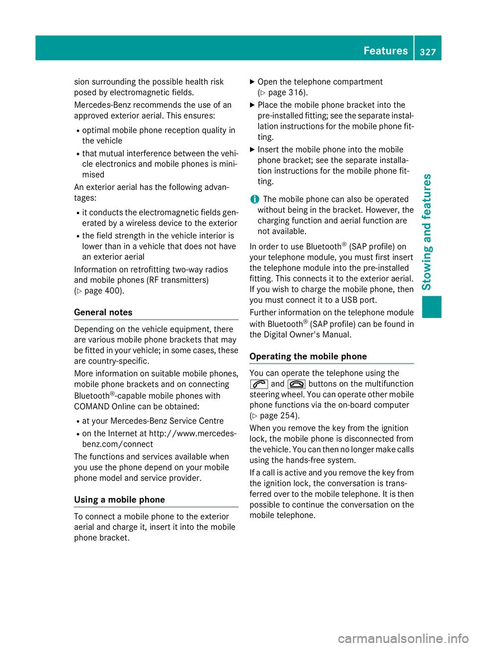
phone bracket. X
Open the telephone compartment
(Y page 316).
X Place the mobile phone bracket into the
pre-installed fitting; see the separate instal-
lation instructions for the mobile phone fit-
ting.
X Insert the mobile phone into the mobile
phone bracket; see the separate installa-
tion instructions for the mobile phone fit-
ting.
i The mobile phone can also be operated
without being in the bracket. However, the charging function and aerial function are
not available.
In order to use Bluetooth ®
(SAP profile) on
your telephone module, you must first insert
the telephone module into the pre-installed
fitting. This connects it to the exterior aerial.
If you wish to charge the mobile phone, then
you must connect it to a USB port.
Further information on the telephone module
with Bluetooth ®
(SAP profile) can be found in
the Digital Owner's Manual.
Operating the mobile phone You can operate the telephone using the
6 and~ buttons on the multifunction
steering wheel. You can operate other mobile
phone functions via the on-board computer
(Y page 254).
When you remove the key from the ignition
lock, the mobile phone is disconnected from
the vehicle. You can then no longer make calls using the hands-free system.
If a call is active and you remove the key from the ignition lock, the conversation is trans-
ferred over to the mobile telephone. It is then
possible to continue the conversation on the
mobile telephone. Features
327Stowing and features Z
Page 331 of 413
Garage door opener
General notes The HomeLink
®
garage door opener integra-
ted in the rear-view mirror allows you to oper- ate up to three different door and gate sys-
tems.
Once programmed, the integrated garage
door opener in the rear-view mirror will
assume the function of the garage door sys-
tem's remote control. Please also read the
operating instructions for the garage door
system.
When programming a garage door opener,
park the vehicle outside the garage. Do not
run the engine while programming.
The garage door opener is only available for
certain countries. Observe the legal require-
ments for each individual country.
The HomeLink ®
garage door opener is com-
patible with most European garage and gate
opener drives. More information on Home-
Link ®
and/or compatible products is availa-
ble:
R at a qualified specialised workshop
R via the HomeLink ®
Hotline
(0) 08000 466 354 65 or alternatively
+49 (0) 6838 907-277
R on the Internet at
http://www.homelink.com
Important safety notes G
WARNING
When you operate or program the garage door with the integrated garage door opener, per-
sons in the range of movement of the garage
door can become trapped or struck by the
garage door. There is a risk of injury.
When using the integrated garage door
opener, always make sure that nobody is
within the range of movement of the garage
door. G
WARNING
Combustion engines emit poisonous exhaust
gases such as carbon monoxide. Inhaling
these exhaust gases leads to poisoning. There is a risk of fatal injury. Therefore never leave
the engine running in enclosed spaces with-
out sufficient ventilation.
Programming Programming buttons
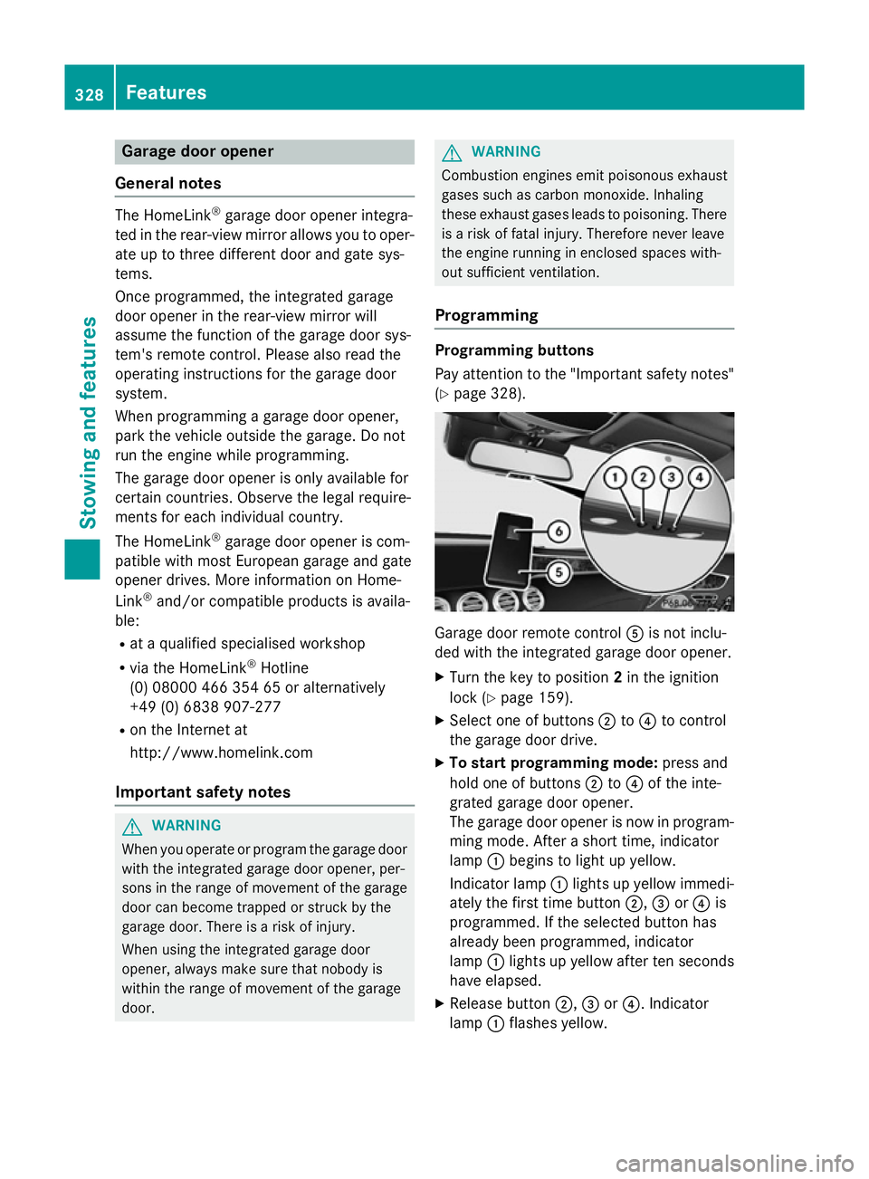
Pay attention to the "Important safety notes"
(Y page 328). Garage door remote control
Ais not inclu-
ded with the integrated garage door opener.
X Turn the key to position 2in the ignition
lock (Y page 159).
X Select one of buttons ;to? to control
the garage door drive.
X To start programming mode: press and
hold one of buttons ;to? of the inte-
grated garage door opener.
The garage door opener is now in program- ming mode. After a short time, indicator
lamp :begins to light up yellow.
Indicator lamp :lights up yellow immedi-
ately the first time button ;,=or? is
programmed. If the selected button has
already been programmed, indicator
lamp :lights up yellow after ten seconds
have elapsed.
X Release button ;,=or?. Indicator
lamp :flashes yellow. 328
FeaturesStowing and features