2014 MERCEDES-BENZ CLS SHOOTING BRAKE Removing
[x] Cancel search: RemovingPage 347 of 417
Useful information
i This Owner's Manual describes all mod-
els, series and optional equipment for your
vehicle that were available at the time of
going to press. National variations are pos- sible. Note that your vehicle may not be
equipped with all of the functions descri-
bed. This is also the case for systems and
functions relevant to safety.
i Read the information on qualified special-
ist workshops: (Y page 26). Where will I find...?
Warning triangle
Removing the warning triangle X
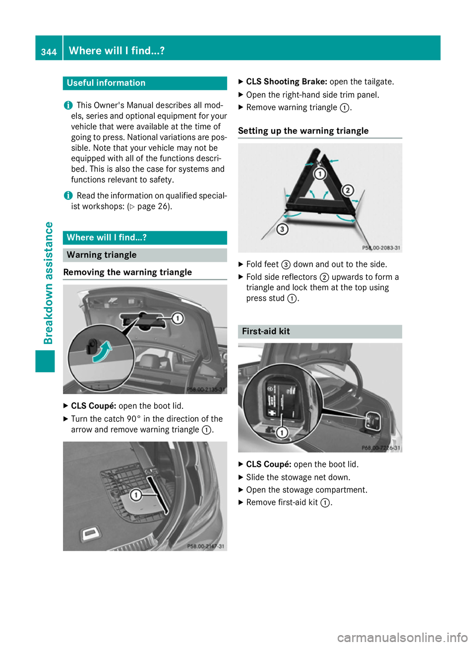
CLS Coupé: open the boot lid.
X Turn the catch 90° in the direction of the
arrow and remove warning triangle :. X
CLS Shooting Brake: open the tailgate.
X Open the right-hand side trim panel.
X Remove warning triangle :.
Setting up the warning triangle X
Fold feet =down and out to the side.
X Fold side reflectors ;upwards to form a
triangle and lock them at the top using
press stud :. First-aid kit
X
CLS Coupé: open the boot lid.
X Slide the stowage net down.
X Open the stowage compartment.
X Remove first-aid kit :.344
Where will I find...?Breakdown assistance
Page 354 of 417
icantly impair the vehicle's braking and driv-
ing characteristics. There is a risk of accident.
Do not continue driving. Contact a qualified
specialist workshop.
i In your vehicle, you will find a sticker with
the Mercedes-Benz Service24h telephone
number, e.g. on the B-pillar on the driver's
side.
X Correct the tyre pressure if it is still at least
130 kPa (1.3 bar/19 psi). See the fuel filler
flap for values.
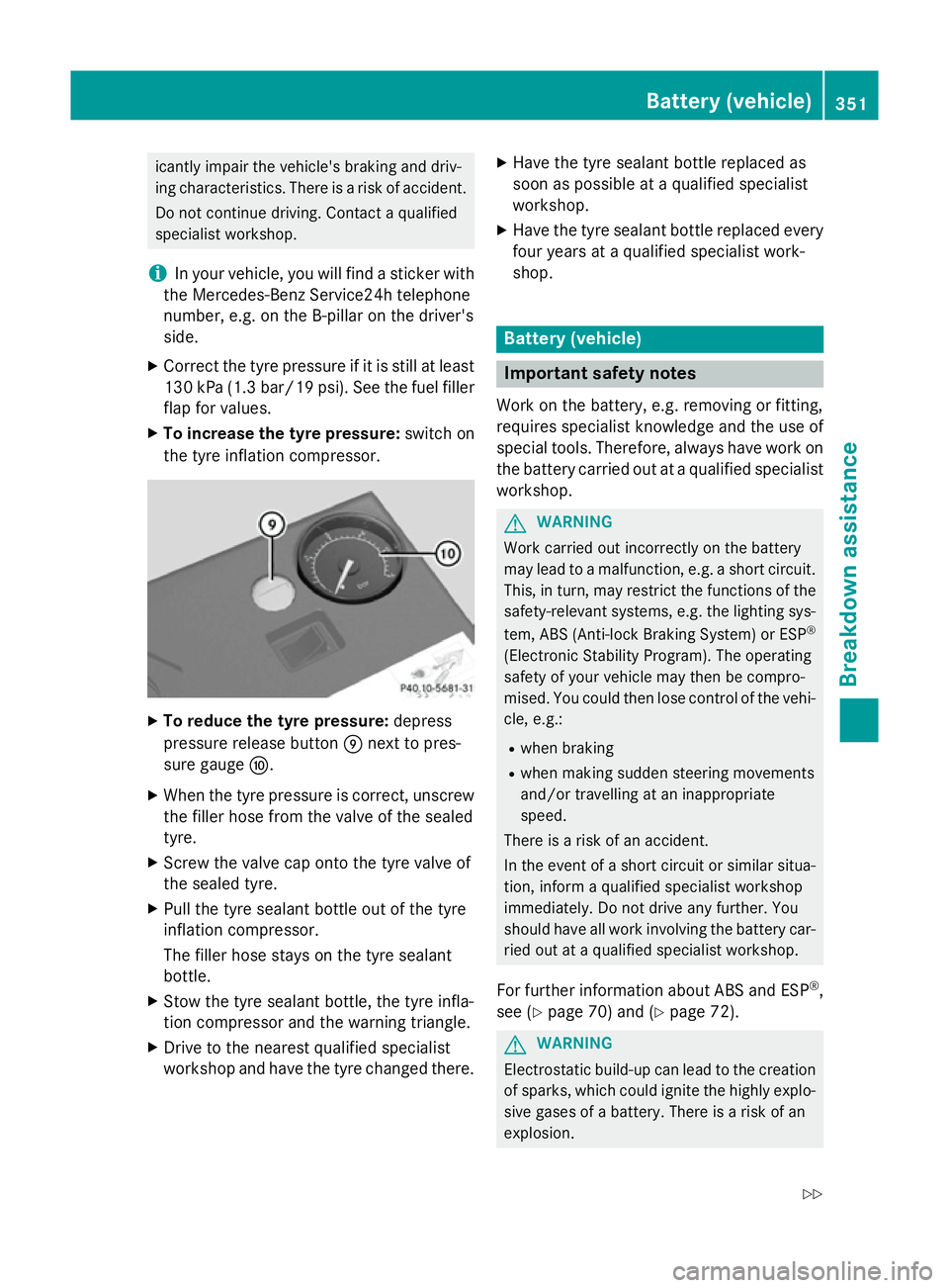
X To increase the tyre pressure: switch on
the tyre inflation compressor. X
To reduce the tyre pressure: depress
pressure release button Enext to pres-
sure gauge F.
X When the tyre pressure is correct, unscrew
the filler hose from the valve of the sealed
tyre.
X Screw the valve cap onto the tyre valve of
the sealed tyre.
X Pull the tyre sealant bottle out of the tyre
inflation compressor.
The filler hose stays on the tyre sealant
bottle.
X Stow the tyre sealant bottle, the tyre infla-
tion compressor and the warning triangle.
X Drive to the nearest qualified specialist
workshop and have the tyre changed there. X
Have the tyre sealant bottle replaced as
soon as possible at a qualified specialist
workshop.
X Have the tyre sealant bottle replaced every
four years at a qualified specialist work-
shop. Battery (vehicle)
Important safety notes
Work on the battery, e.g. removing or fitting,
requires specialist knowledge and the use of
special tools. Therefore, always have work on the battery carried out at a qualified specialist
workshop. G
WARNING
Work carried out incorrectly on the battery
may lead to a malfunction, e.g. a short circuit. This, in turn, may restrict the functions of the
safety-relevant systems, e.g. the lighting sys-
tem, ABS (Anti-lock Braking System) or ESP ®
(Electronic Stability Program). The operating
safety of your vehicle may then be compro-
mised. You could then lose control of the vehi-
cle, e.g.:
R when braking
R when making sudden steering movements
and/or travelling at an inappropriate
speed.
There is a risk of an accident.
In the event of a short circuit or similar situa-
tion, inform a qualified specialist workshop
immediately. Do not drive any further. You
should have all work involving the battery car- ried out at a qualified specialist workshop.
For further information about ABS and ESP ®
,
see (Y page 70) and (Y page 72). G
WARNING
Electrostatic build-up can lead to the creation of sparks, which could ignite the highly explo-
sive gases of a battery. There is a risk of an
explosion. Battery (vehicle)
351Breakdown assistance
Z
Page 360 of 417
X
First, remove the jump leads from earth point Aand negative terminal ?, then from pos-
itive clamp ;and positive terminal =. Begin each time at the contacts on your own vehicle
first.
X Close cover :of positive clamp ;after removing the jump leads.
X Have the battery checked at a qualified specialist workshop.
i Jump-starting is not considered to be a normal operating condition.
i Jump-starting cables and further information regarding jump starting can be obtained at
any qualified specialist workshop. Towing and tow-starting
Important safety notes
G
WARNING
Safety-relevant functions are restricted or not
available if:
R the engine is not running.
R the brake system or the power steering is
malfunctioning
R the voltage supply or the vehicle's electrical
system is malfunctioning.
If your vehicle is towed, significantly greater
force may be required to steer the vehicle or
to brake. There is a risk of an accident.
In such circumstances, use a towing bar.
Make sure that the steering is moving freely
before towing. G
WARNING
If the weight of the vehicle to be towed or tow- started is greater than the permissible gross
weight of your vehicle:
R the towing eye could detach itself
R the vehicle/trailer combination could over-
turn.
There is a risk of an accident.
When towing or tow-starting another vehicle,
its weight should not be greater than the per-
missible gross weight of your vehicle.
i Information on your vehicle's gross vehi-
cle weight rating can be found on the vehi-
cle identification plate (Y page 398).!
If DISTRONIC PLUS or the HOLD function
is activated, the vehicle brakes automati-
cally in certain situations. To prevent dam-
age to the vehicle, deactivate DISTRONIC
PLUS and the HOLD function in the follow-
ing or other similar situations:
R when towing the vehicle
R in the car wash
! Only secure the tow cable or tow bar to
the towing eyes or, if available, to the trailer
tow hitch. You could otherwise damage the
vehicle.
! Observe the following points when towing
with a tow rope:
R Secure the tow rope on the same side on
both vehicles.
R Make sure that the tow rope is not longer
than legally permitted. Mark the tow rope
in the middle, e.g. with a white cloth
(30 x 30 cm). This will make other road
users aware that a vehicle is being
towed.
R Only secure the tow cable to the towing
eyes or, if available, to the trailer tow
hitch.
R Observe the brake lamps of the towing
vehicle while driving. Always maintain a
distance a distance so that the tow rope
does not sag.
R Do not use steel cables or chains to tow
your vehicle. You could otherwise dam-
age the vehicle. Towing and tow-starting
357Breakdown assistance Z
Page 361 of 417
!
Do not use the towing eye for recovery,
this could damage the vehicle. If in doubt,
recover the vehicle with a crane.
! When towing, pull away slowly and
smoothly. If the tractive power is too high,
the vehicles could be damaged.
! To tow vehicles with KEYLESS-GO, use
the key instead of the Start/Stop button.
The automatic transmission may otherwise switch to position Pwhen you open the
driver's or front-passenger door which
could damage the transmission.
! You may tow the vehicle for a maximum of
50km. A towing speed of 50 km/h must not be exceeded.
For towing distances over 50 km, the entire
vehicle must be lifted up and transported.
! If you tow or tow-start another vehicle, its
weight must not exceed the maximum per- missible gross vehicle weight of your vehi-
cle.
Observe the legal requirements for the rele-
vant countries when towing.
It is better to have the vehicle transported
than to have it towed.
If the vehicle has suffered transmission dam-
age, have it transported on a transporter or
trailer.
The automatic transmission must be in posi-
tion Nwhen the vehicle is being towed.
The battery must be connected and charged. Otherwise, you:
R cannot turn the key in the ignition lock to
position 2
R cannot shift the automatic transmission to
position N
i Deactivate the automatic locking feature
before the vehicle is towed away
(Y page 90). You could otherwise be locked
out when pushing or towing the vehicle.
i Deactivate tow-away protection before
the vehicle is towed away (Y page 79). Fitting/removing the towing eye
Fitting the towing eye G
WARNING
The exhaust tail pipe may be extremely hot.
There is a risk of burning when removing the
rear cover.
Do not touch the exhaust tail pipe. Use
extreme caution when removing the rear
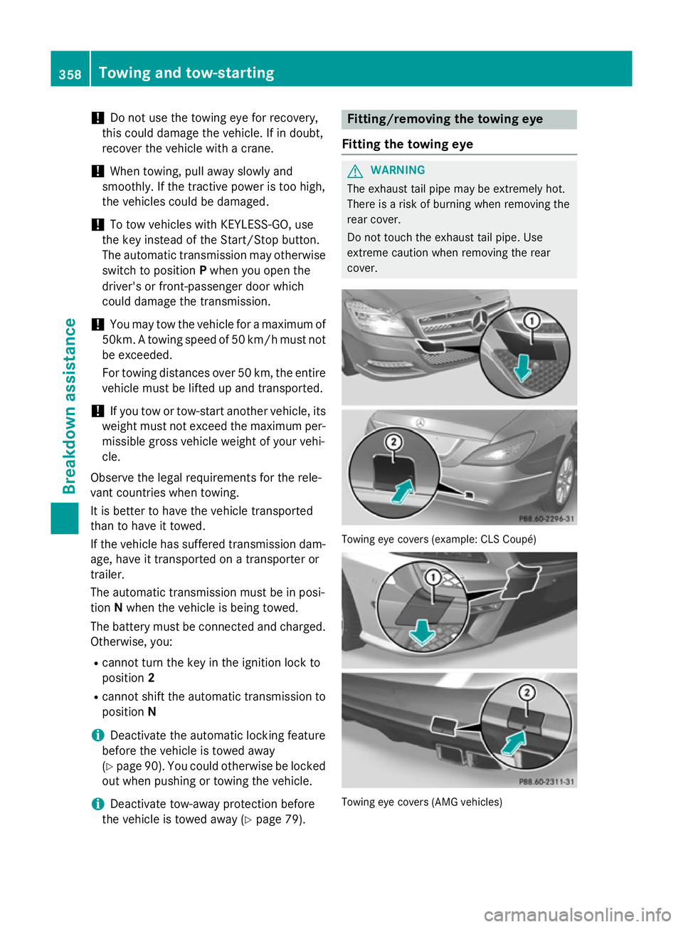
cover. Towing eye covers (example: CLS Coupé)
Towing eye covers (AMG vehicles)358
Towing and tow-startingBreakdown assistance
Page 362 of 417
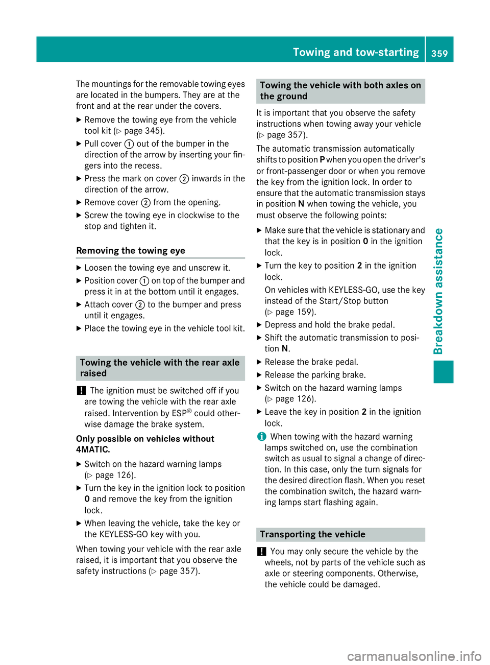
The mountings for the removable towing eyes
are located in the bumpers. They are at the
front and at the rear under the covers.
X Remove the towing eye from the vehicle
tool kit (Y page 345).
X Pull cover :out of the bumper in the
direction of the arrow by inserting your fin-
gers into the recess.
X Press the mark on cover ;inwards in the
direction of the arrow.
X Remove cover ;from the opening.
X Screw the towing eye in clockwise to the
stop and tighten it.
Removing the towing eye X
Loosen the towing eye and unscrew it.
X Position cover :on top of the bumper and
press it in at the bottom until it engages.
X Attach cover ;to the bumper and press
until it engages.
X Place the towing eye in the vehicle tool kit. Towing the vehicle with the rear axle
raised
! The ignition must be switched off if you
are towing the vehicle with the rear axle
raised. Intervention by ESP ®
could other-
wise damage the brake system.
Only possible on vehicles without
4MATIC.
X Switch on the hazard warning lamps
(Y page 126).
X Turn the key in the ignition lock to position
0 and remove the key from the ignition
lock.
X When leaving the vehicle, take the key or
the KEYLESS-GO key with you.
When towing your vehicle with the rear axle
raised, it is important that you observe the
safety instructions (Y page 357). Towing the vehicle with both axles on
the ground
It is important that you observe the safety
instructions when towing away your vehicle
(Y page 357).
The automatic transmission automatically
shifts to position Pwhen you open the driver's
or front-passenger door or when you remove the key from the ignition lock. In order to
ensure that the automatic transmission stays
in position Nwhen towing the vehicle, you
must observe the following points:
X Make sure that the vehicle is stationary and
that the key is in position 0in the ignition
lock.
X Turn the key to position 2in the ignition
lock.
On vehicles with KEYLESS-GO, use the key instead of the Start/Stop button
(Y page 159).
X Depress and hold the brake pedal.
X Shift the automatic transmission to posi-
tion N.
X Release the brake pedal.
X Release the parking brake.
X Switch on the hazard warning lamps
(Y page 126).
X Leave the key in position 2in the ignition
lock.
i When towing with the hazard warning
lamps switched on, use the combination
switch as usual to signal a change of direc- tion. In this case, only the turn signals for
the desired direction flash. When you reset
the combination switch, the hazard warn-
ing lamps start flashing again. Transporting the vehicle
! You may only secure the vehicle by the
wheels, not by parts of the vehicle such as
axle or steering components. Otherwise,
the vehicle could be damaged. Towing and tow-starting
359Breakdown assistance Z
Page 380 of 417
Removing a wheel
!
AMG vehicles:
during removal and repo-
sitioning of the wheel, the wheel rim can
strike the ceramic-brake disc and damage
it. Therefore, take precautions and get a
second person to assist you. Alternatively,
you can use a second centring pin.
! Do not place wheel bolts in sand or dirt.
The threads of the wheel bolts and wheel
hubs could otherwise be damaged when
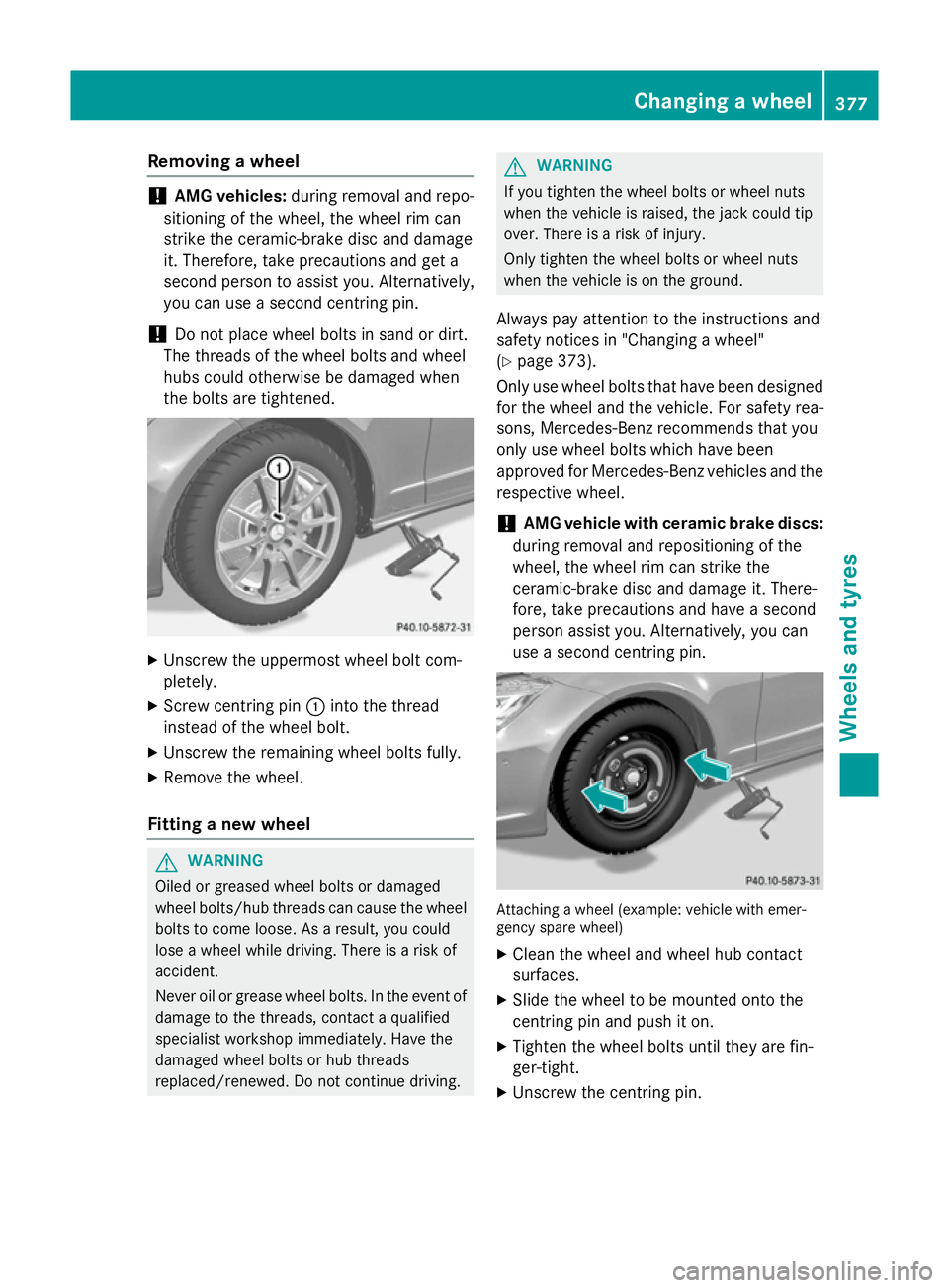
the bolts are tightened. X
Unscrew the uppermost wheel bolt com-
pletely.
X Screw centring pin :into the thread
instead of the wheel bolt.
X Unscrew the remaining wheel bolts fully.
X Remove the wheel.
Fitting a new wheel G
WARNING
Oiled or greased wheel bolts or damaged
wheel bolts/hub threads can cause the wheel bolts to come loose. As a result, you could
lose a wheel while driving. There is a risk of
accident.
Never oil or grease wheel bolts. In the event of damage to the threads, contact a qualified
specialist workshop immediately. Have the
damaged wheel bolts or hub threads
replaced/renewed. Do not continue driving. G
WARNING
If you tighten the wheel bolts or wheel nuts
when the vehicle is raised, the jack could tip
over. There is a risk of injury.
Only tighten the wheel bolts or wheel nuts
when the vehicle is on the ground.
Always pay attention to the instructions and
safety notices in "Changing a wheel"
(Y page 373).
Only use wheel bolts that have been designed
for the wheel and the vehicle. For safety rea-
sons, Mercedes-Benz recommends that you
only use wheel bolts which have been
approved for Mercedes-Benz vehicles and the
respective wheel.
! AMG vehicle with ceramic brake discs:
during removal and repositioning of the
wheel, the wheel rim can strike the
ceramic-brake disc and damage it. There-
fore, take precautions and have a second
person assist you. Alternatively, you can
use a second centring pin. Attaching a wheel (example: vehicle with emer-
gency spare wheel)
X Clean the wheel and wheel hub contact
surfaces.
X Slide the wheel to be mounted onto the
centring pin and push it on.
X Tighten the wheel bolts until they are fin-
ger-tight.
X Unscrew the centring pin. Changing a wheel
377Wheels and tyres Z
Page 394 of 417
R
Do not switch off ESP ®
.
R Have the spare wheel/emergency spare
wheel in question replaced at the nearest
qualified specialist workshop. Make sure
that the wheel/tyre dimensions and tyre
type are correct.
When using an emergency spare wheel or
spare wheel of a different size, you must not
exceed the maximum speed of 80 km/h.
Snow chains must not be fitted to emergency spare wheels. General notes
You should regularly check the pressure of all your tyres, including the emergency spare
wheel, particularly prior to long trips, and cor-
rect the pressure as necessary (Y page 367).
The value on the wheel is valid. In addition, the
emergency spare wheel tyre pressure can be found under "Technical data" (Y page 394).
An emergency spare wheel may also be fitted against the direction of rotation. Observe the
time restriction on use as well as the speed
limitation specified on the emergency spare
wheel.
Replace the tyres after six years at the latest,
regardless of wear. This also applies to the
emergency spare wheel.
i If you are driving with the collapsible
emergency spare wheel fitted, the tyre
pressure loss warning system or the tyre
pressure monitor cannot function reliably.
Only restart the tyre pressure loss warning
system/tyre pressure monitor when the
defective wheel has been replaced with a
new wheel.
Vehicles with tyre pressure monitor: after
mounting an emergency spare wheel, the
system may still display the tyre pressure of the removed wheel for a few minutes. The
value displayed for the mounted emer-
gency spare wheel is not the same as the
current tyre pressure of the emergency
spare wheel. Removing the "Minispare" emer-
gency spare wheel/collapsible emer-
gency spare wheel
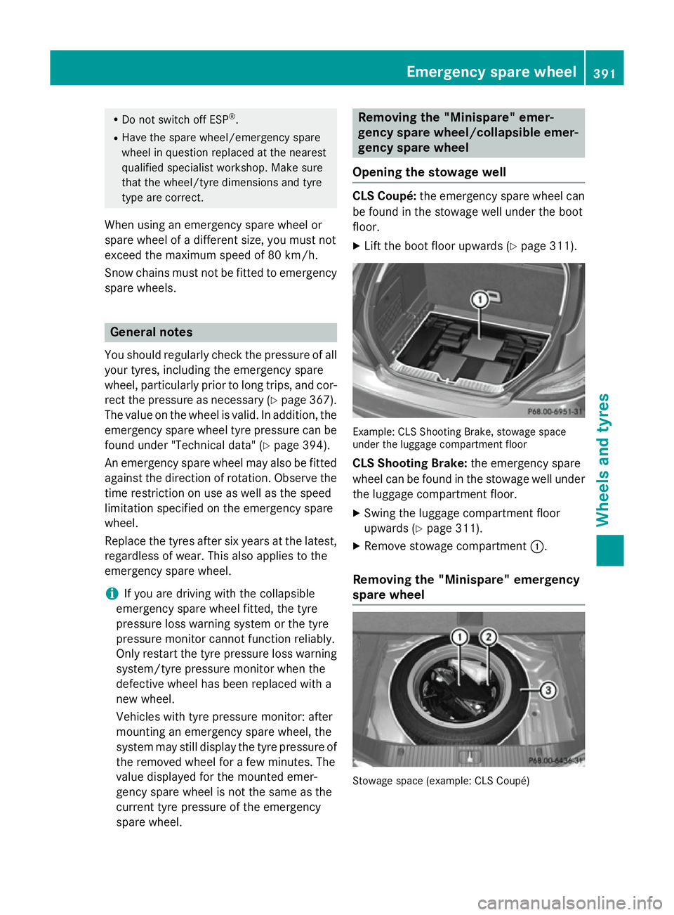
Opening the stowage well CLS Coupé:
the emergency spare wheel can
be found in the stowage well under the boot
floor.
X Lift the boot floor upwards (Y page 311). Example: CLS Shooting Brake, stowage space
under the luggage compartment floor
CLS Shooting Brake: the emergency spare
wheel can be found in the stowage well under
the luggage compartment floor.
X Swing the luggage compartment floor
upwards (Y page 311).
X Remove stowage compartment :.
Removing the "Minispare" emergency
spare wheel Stowage space (example: CLS Coupé) Emergency spare
wheel
391Wheels an d tyres Z
Page 395 of 417
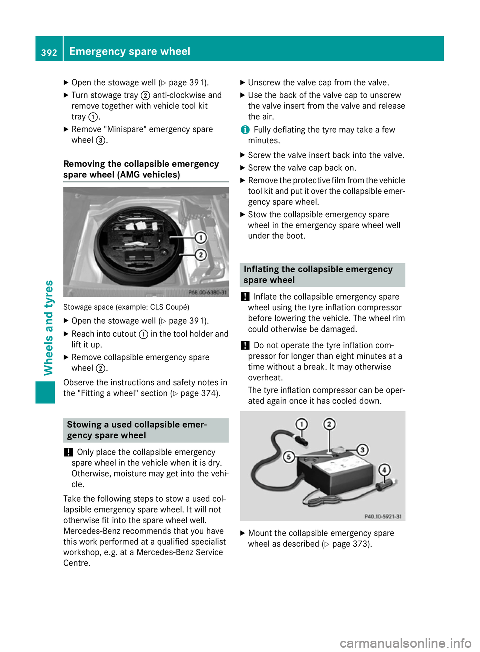
X
Open the stowage well (Y page 391).
X Turn stowage tray ;anti-clockwise and
remove together with vehicle tool kit
tray :.
X Remove "Minispare" emergency spare
wheel =.
Removing the collapsible emergency
spare wheel (AMG vehicles) Stowage space (example: CLS Coupé)
X Open the stowage well (Y page 391).
X Reach into cutout :in the tool holder and
lift it up.
X Remove collapsible emergency spare
wheel ;.
Observe the instructions and safety notes in
the "Fitting a wheel" section (Y page 374).Stowing a used collapsible emer-
gency spare wheel
! Only place the collapsible emergency
spare wheel in the vehicle when it is dry.
Otherwise, moisture may get into the vehi-
cle.
Take the following steps to stow a used col-
lapsible emergency spare wheel. It will not
otherwise fit into the spare wheel well.
Mercedes-Benz recommends that you have
this work performed at a qualified specialist
workshop, e.g. at a Mercedes-Benz Service
Centre. X
Unscrew the valve cap from the valve.
X Use the back of the valve cap to unscrew
the valve insert from the valve and release
the air.
i Fully deflating the tyre may take a few
minutes.
X Screw the valve insert back into the valve.
X Screw the valve cap back on.
X Remove the protective film from the vehicle
tool kit and put it over the collapsible emer-
gency spare wheel.
X Stow the collapsible emergency spare
wheel in the emergency spare wheel well
under the boot. Inflating the collapsible emergency
spare wheel
! Inflate the collapsible emergency spare
wheel using the tyre inflation compressor
before lowering the vehicle. The wheel rim
could otherwise be damaged.
! Do not operate the tyre inflation com-
pressor for longer than eight minutes at a
time without a break. It may otherwise
overheat.
The tyre inflation compressor can be oper-
ated again once it has cooled down. X
Mount the collapsible emergency spare
wheel as described (Y page 373).392
Emergency spare wheelWheels and tyres