2014 MERCEDES-BENZ CLS COUPE clock
[x] Cancel search: clockPage 304 of 417
thrown around and hit vehicle occupants.
There is a risk of injury, particularly in the
event of sudden braking or a sudden change
in direction.
R Always stow objects so that they cannot be
thrown around in such situations.
R Always make sure that objects do not pro-
trude from stowage spaces, luggage nets or
stowage nets.
R Close the lockable stowage spaces while
driving.
R Always stow and secure heavy, hard, poin-
ted, sharp-edged, fragile or bulky objects in
the boot/luggage compartment.
Observe the loading guidelines (Y page 300).
Glove compartment X
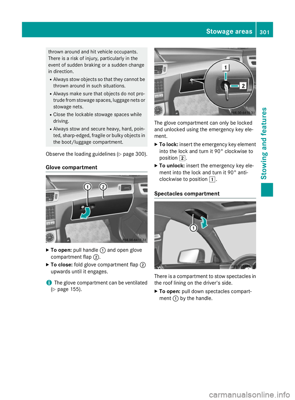
To open: pull handle :and open glove
compartment flap ;.
X To close: fold glove compartment flap ;
upwards until it engages.
i The glove compartment can be ventilated
(Y page 155). The glove compartment can only be locked
and unlocked using the emergency key ele-
ment.
X To lock: insert the emergency key element
into the lock and turn it 90° clockwise to
position 2.
X To unlock: insert the emergency key ele-
ment into the lock and turn it 90° anti-
clockwise to position 1.
Spectacles compartment There is a compartment to stow spectacles in
the roof lining on the driver's side.
X To open: pull down spectacles compart-
ment :by the handle. Sto
wage areas
301Stowing and features Z
Page 312 of 417
Always observe the maximum permitted
load of the EASY-PACK boot box. Always
store and secure heavy objects in the boot outside of the EASY-PACK boot box.
The maximum permitted load of the EASY-
PACK boot box is 10 kg. With a load of above approximately 5 kg, the bottom of the box
moves downward until it rests on the mat of
the boot floor. Thus, overloading of the box is
avoided.
Adjusting the height to any position X
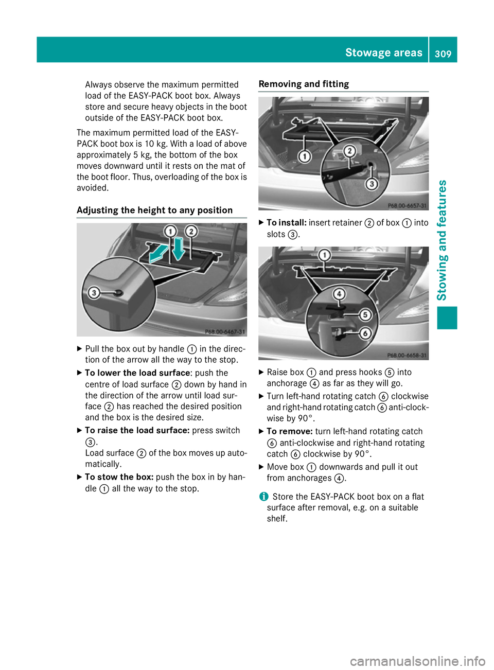
Pull the box out by handle :in the direc-
tion of the arrow all the way to the stop.
X To lower the load surface: push the
centre of load surface ;down by hand in
the direction of the arrow until load sur-
face ;has reached the desired position
and the box is the desired size.
X To raise the load surface: press switch
=.
Load surface ;of the box moves up auto-
matically.
X To stow the box: push the box in by han-
dle :all the way to the stop. Removing and fitting X
To install: insert retainer ;of box :into
slots =. X
Raise box :and press hooks Ainto
anchorage ?as far as they will go.
X Turn left-hand rotating catch Bclockwise
and right-hand rotating catch Banti-clock-
wise by 90°.
X To remove: turn left-hand rotating catch
B anti-clockwise and right-hand rotating
catch Bclockwise by 90°.
X Move box :downwards and pull it out
from anchorages ?.
i Store the EASY-PACK boot box on a flat
surface after removal, e.g. on a suitable
shelf. Stowage areas
309Stowing an d features Z
Page 334 of 417
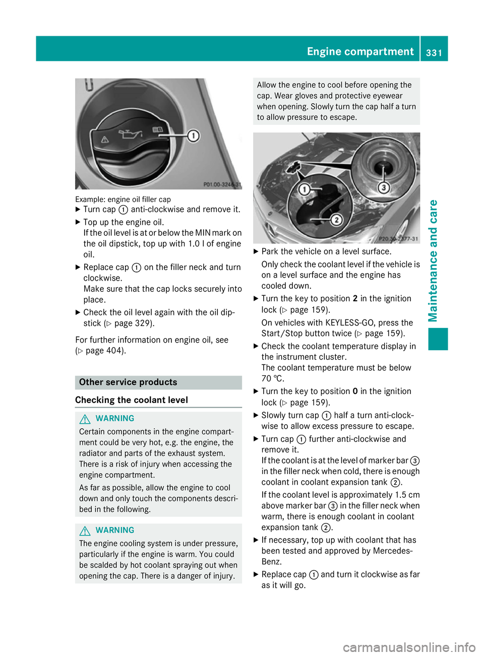
Example: engine oil filler cap
X Turn cap :anti-clockwise and remove it.
X Top up the engine oil.
If the oil level is at or below the MIN mark on
the oil dipstick, top up with 1.0 lof engine
oil.
X Replace cap :on the filler neck and turn
clockwise.
Make sure that the cap locks securely into place.
X Check the oil level again with the oil dip-
stick (Y page 329).
For further information on engine oil, see
(Y page 404). Other service products
Checking the coolant level G
WARNING
Certain components in the engine compart-
ment could be very hot, e.g. the engine, the
radiator and parts of the exhaust system.
There is a risk of injury when accessing the
engine compartment.
As far as possible, allow the engine to cool
down and only touch the components descri- bed in the following. G
WARNING
The engine cooling system is under pressure, particularly if the engine is warm. You could
be scalded by hot coolant spraying out when
opening the cap. There is a danger of injury. Allow the engine to cool before opening the
cap. Wear gloves and protective eyewear
when opening. Slowly turn the cap half a turn
to allow pressure to escape. X
Park the vehicle on a level surface.
Only check the coolant level if the vehicle is
on a level surface and the engine has
cooled down.
X Turn the key to position 2in the ignition
lock (Y page 159).
On vehicles with KEYLESS-GO, press the
Start/Stop button twice (Y page 159).
X Check the coolant temperature display in
the instrument cluster.
The coolant temperature must be below
70 †.
X Turn the key to position 0in the ignition
lock (Y page 159).
X Slowly turn cap :half a turn anti-clock-
wise to allow excess pressure to escape.
X Turn cap :further anti-clockwise and
remove it.
If the coolant is at the level of marker bar =
in the filler neck when cold, there is enough coolant in coolant expansion tank ;.
If the coolant level is approximately 1.5 cm above marker bar =in the filler neck when
warm, there is enough coolant in coolant
expansion tank ;.
X If necessary, top up with coolant that has
been tested and approved by Mercedes-
Benz.
X Replace cap :and turn it clockwise as far
as it will go. Engine compartment
331Maintenance and care Z
Page 356 of 417
The battery and the cover of the positive
terminal clamp must be fitted securely dur-
ing operation.
Comply with safety precautions and take pro-
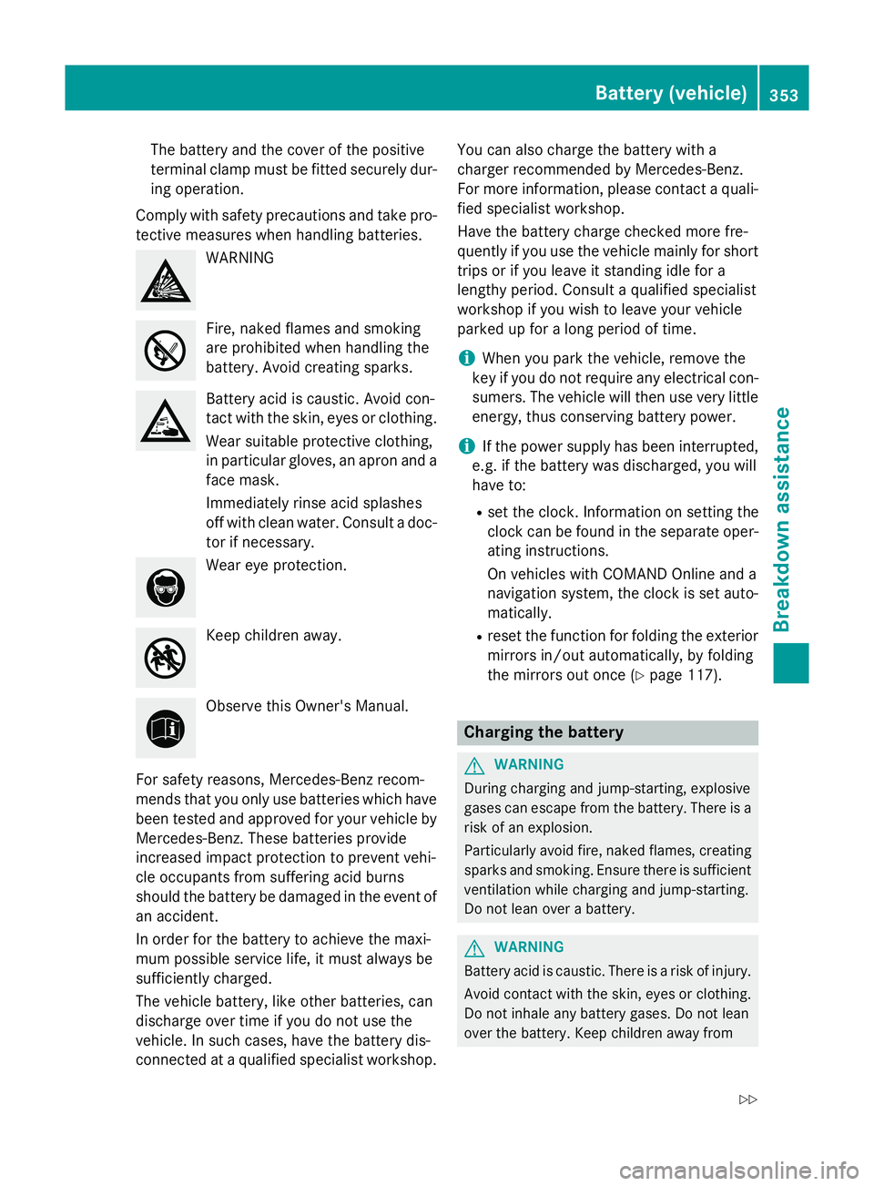
tective measures when handling batteries. WARNING
Fire, naked flames and smoking
are prohibited when handling the
battery. Avoid creating sparks.
Battery acid is caustic. Avoid con-
tact with the skin, eyes or clothing.
Wear suitable protective clothing,
in particular gloves, an apron and a
face mask.
Immediately rinse acid splashes
off with clean water. Consult a doc-
tor if necessary. Wear eye protection.
Keep children away.
Observe this Owner's Manual.
For safety reasons, Mercedes-Benz recom-
mends that you only use batteries which have been tested and approved for your vehicle by
Mercedes-Benz. These batteries provide
increased impact protection to prevent vehi-
cle occupants from suffering acid burns
should the battery be damaged in the event of
an accident.
In order for the battery to achieve the maxi-
mum possible service life, it must always be
sufficiently charged.
The vehicle battery, like other batteries, can
discharge over time if you do not use the
vehicle. In such cases, have the battery dis-
connected at a qualified specialist workshop. You can also charge the battery with a
charger recommended by Mercedes-Benz.
For more information, please contact a quali-
fied specialist workshop.
Have the battery charge checked more fre-
quently if you use the vehicle mainly for short
trips or if you leave it standing idle for a
lengthy period. Consult a qualified specialist
workshop if you wish to leave your vehicle
parked up for a long period of time.
i When you park the vehicle, remove the
key if you do not require any electrical con-
sumers. The vehicle will then use very little energy, thus conserving battery power.
i If the power supply has been interrupted,
e.g. if the battery was discharged, you will
have to:
R set the clock. Information on setting the
clock can be found in the separate oper-
ating instructions.
On vehicles with COMAND Online and a
navigation system, the clock is set auto- matically.
R reset the function for folding the exterior
mirrors in/out automatically, by folding
the mirrors out once (Y page 117). Charging the battery
G
WARNING
During charging and jump-starting, explosive
gases can escape from the battery. There is a risk of an explosion.
Particularly avoid fire, naked flames, creating
sparks and smoking. Ensure there is sufficient
ventilation while charging and jump-starting.
Do not lean over a battery. G
WARNING
Battery acid is caustic. There is a risk of injury. Avoid contact with the skin, eyes or clothing.
Do not inhale any battery gases. Do not lean
over the battery. Keep children away from Battery (vehicle)
353Breakdown assistance
Z
Page 362 of 417
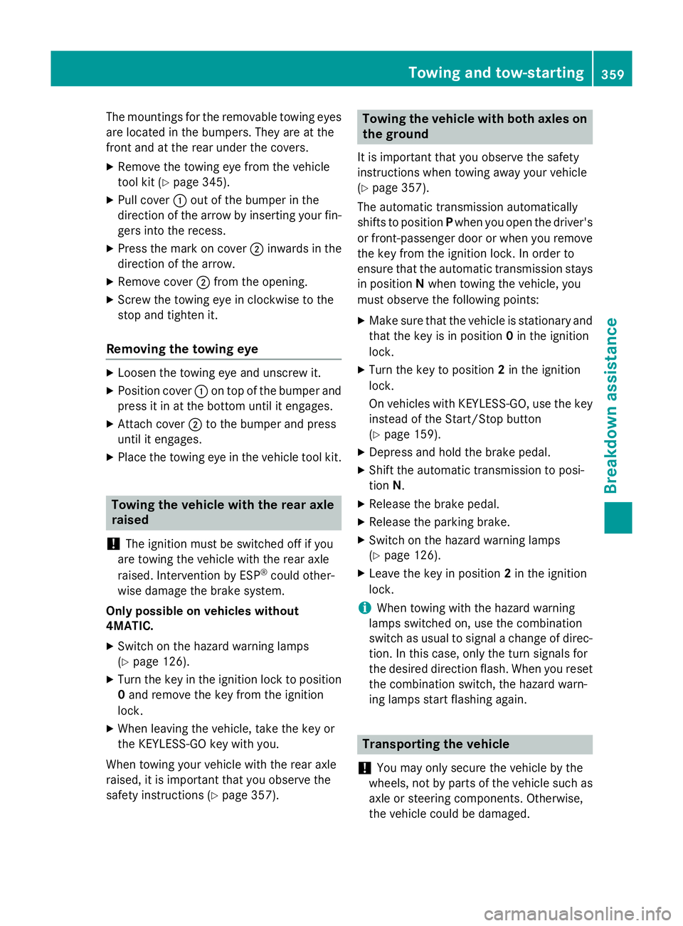
The mountings for the removable towing eyes
are located in the bumpers. They are at the
front and at the rear under the covers.
X Remove the towing eye from the vehicle
tool kit (Y page 345).
X Pull cover :out of the bumper in the
direction of the arrow by inserting your fin-
gers into the recess.
X Press the mark on cover ;inwards in the
direction of the arrow.
X Remove cover ;from the opening.
X Screw the towing eye in clockwise to the
stop and tighten it.
Removing the towing eye X
Loosen the towing eye and unscrew it.
X Position cover :on top of the bumper and
press it in at the bottom until it engages.
X Attach cover ;to the bumper and press
until it engages.
X Place the towing eye in the vehicle tool kit. Towing the vehicle with the rear axle
raised
! The ignition must be switched off if you
are towing the vehicle with the rear axle
raised. Intervention by ESP ®
could other-
wise damage the brake system.
Only possible on vehicles without
4MATIC.
X Switch on the hazard warning lamps
(Y page 126).
X Turn the key in the ignition lock to position
0 and remove the key from the ignition
lock.
X When leaving the vehicle, take the key or
the KEYLESS-GO key with you.
When towing your vehicle with the rear axle
raised, it is important that you observe the
safety instructions (Y page 357). Towing the vehicle with both axles on
the ground
It is important that you observe the safety
instructions when towing away your vehicle
(Y page 357).
The automatic transmission automatically
shifts to position Pwhen you open the driver's
or front-passenger door or when you remove the key from the ignition lock. In order to
ensure that the automatic transmission stays
in position Nwhen towing the vehicle, you
must observe the following points:
X Make sure that the vehicle is stationary and
that the key is in position 0in the ignition
lock.
X Turn the key to position 2in the ignition
lock.
On vehicles with KEYLESS-GO, use the key instead of the Start/Stop button
(Y page 159).
X Depress and hold the brake pedal.
X Shift the automatic transmission to posi-
tion N.
X Release the brake pedal.
X Release the parking brake.
X Switch on the hazard warning lamps
(Y page 126).
X Leave the key in position 2in the ignition
lock.
i When towing with the hazard warning
lamps switched on, use the combination
switch as usual to signal a change of direc- tion. In this case, only the turn signals for
the desired direction flash. When you reset
the combination switch, the hazard warn-
ing lamps start flashing again. Transporting the vehicle
! You may only secure the vehicle by the
wheels, not by parts of the vehicle such as
axle or steering components. Otherwise,
the vehicle could be damaged. Towing and tow-starting
359Breakdown assistance Z
Page 365 of 417
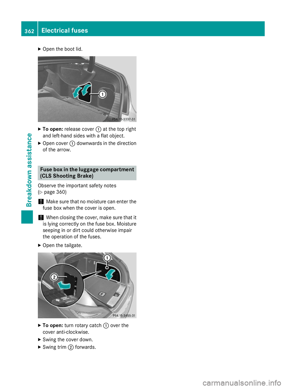
X
Open the boot lid. X
To open: release cover :at the top right
and left-hand sides with a flat object.
X Open cover :downwards in the direction
of the arrow. Fuse box in the luggage compartment
(CLS Shooting Brake)
Observe the important safety notes
(Y page 360)
! Make sure that no moisture can enter the
fuse box when the cover is open.
! When closing the cover, make sure that it
is lying correctly on the fuse box. Moisture seeping in or dirt could otherwise impair
the operation of the fuses.
X Open the tailgate. X
To open: turn rotary catch :over the
cover anti-clockwise.
X Swing the cover down.
X Swing trim ;forwards. 362
Electrical fusesBreakdown assistance
Page 379 of 417
R
before raising the vehicle, secure it from
rolling away by applying the parking brake
and positioning wheel chocks. Never
release the parking brake while the vehicle
is raised.
R the jack must be placed on a firm, flat and
non-slip surface. On a loose surface, a
large, flat load-bearing underlay must be
used. On a slippery surface, a non-slip
underlay must be used, e.g. rubber mats.
R do not use wooden blocks or similar
objects as a jack underlay. Otherwise, the
jack will not be able to achieve its load-
bearing capacity due to the restricted
height.
R make sure that the distance between the
underside of the tyres and the ground does
not exceed 3 cm.
R never place your hands or feet under the
raised vehicle.
R do not lie under the vehicle.
R do not start the engine when the vehicle is
raised.
R do not open or close a door or the boot lid/
tailgate when the vehicle is raised.
R make sure that no persons are present in
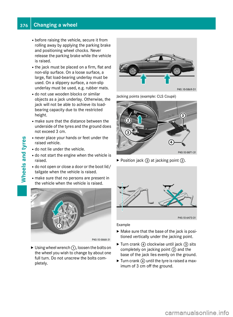
the vehicle when the vehicle is raised. X
Using wheel wrench :, loosen the bolts on
the wheel you wish to change by about one full turn. Do not unscrew the bolts com-
pletely. Jacking points (example: CLS Coupé)
X
Position jack =at jacking point ;. Example
X Make sure that the base of the jack is posi-
tioned vertically under the jacking point.
X Turn crank ?clockwise until jack =sits
completely on jacking point ;and the
base of the jack lies evenly on the ground.
X Turn crank ?until the tyre is raised a max-
imum of 3 cm off the ground. 376
Changing a wheelWheels and tyres
Page 381 of 417
X
Tighten the last wheel bolt until it is finger-
tight.
X Vehicles with a collapsible emergency
spare wheel: inflate the collapsible emer-
gency spare wheel (Y page 392).
Only then lower the vehicle.
Lowering the vehicle G
WARNING
The wheels could work loose if the wheel nuts and bolts are not tightened to the specified
tightening torque. There is a risk of accident.
Have the tightening torque immediately
checked at a qualified specialist workshop
after a wheel is changed.
! Vehicles with a collapsible emergency
spare wheel: Inflate the collapsible emer-
gency spare wheel using the tyre inflation
compressor before lowering the vehicle.
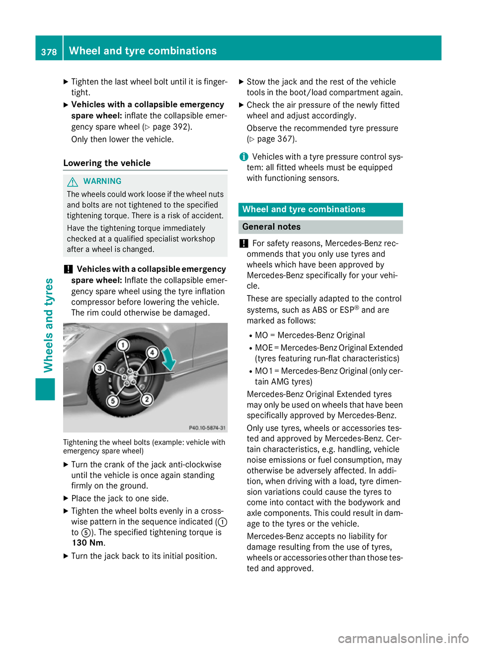
The rim could otherwise be damaged. Tightening the wheel bolts (example: vehicle with
emergency spare wheel)
X Turn the crank of the jack anti-clockwise
until the vehicle is once again standing
firmly on the ground.
X Place the jack to one side.
X Tighten the wheel bolts evenly in a cross-
wise pattern in the sequence indicated ( :
to A). The specified tightening torque is
130 Nm.
X Turn the jack back to its initial position. X
Stow the jack and the rest of the vehicle
tools in the boot/load compartment again.
X Check the air pressure of the newly fitted
wheel and adjust accordingly.
Observe the recommended tyre pressure
(Y page 367).
i Vehicles with a tyre pressure control sys-
tem: all fitted wheels must be equipped
with functioning sensors. Wheel and tyre combinations
General notes
! For safety reasons, Mercedes-Benz rec-
ommends that you only use tyres and
wheels which have been approved by
Mercedes-Benz specifically for your vehi-
cle.
These are specially adapted to the control
systems, such as ABS or ESP ®
and are
marked as follows:
R MO = Mercedes-Benz Original
R MOE = Mercedes-Benz Original Extended
(tyres featuring run-flat characteristics)
R MO1 = Mercedes-Benz Original (only cer-
tain AMG tyres)
Mercedes-Benz Original Extended tyres
may only be used on wheels that have been
specifically approved by Mercedes-Benz.
Only use tyres, wheels or accessories tes-
ted and approved by Mercedes-Benz. Cer-
tain characteristics, e.g. handling, vehicle
noise emissions or fuel consumption, may
otherwise be adversely affected. In addi-
tion, when driving with a load, tyre dimen-
sion variations could cause the tyres to
come into contact with the bodywork and
axle components. This could result in dam- age to the tyres or the vehicle.
Mercedes-Benz accepts no liability for
damage resulting from the use of tyres,
wheels or accessories other than those tes-
ted and approved. 378
Wheel and tyre combinationsWheels and tyres