2014 MERCEDES-BENZ CLS COUPE clock
[x] Cancel search: clockPage 181 of 417
If you mix diesel fuel with petrol, the flash
point of this fuel mixture is lower than that of pure diesel fuel. When the engine is running,
components in the exhaust system may over-
heat unnoticed. There is a risk of fire.
Never refuel with petrol. Never add petrol to
diesel fuel.
! Do not use petrol to refuel vehicles with a
diesel engine. Do not use diesel to refuel
vehicles with a petrol engine. Do not switch on the ignition if you accidentally refuel
with the wrong fuel. Otherwise, the fuel will enter the fuel system. Even small amounts
of the wrong fuel could result in damage to the fuel system and the engine. The repair
costs are high. Notify a qualified specialist
workshop and have the fuel tank and fuel
lines drained completely.
! Overfilling the fuel tank could damage the
fuel system.
! Take care not to spill any fuel on painted
surfaces. You could otherwise damage the
paintwork.
! Use a filter when adding fuel from a fuel
can. The fuel lines and/or the diesel injec-
tion system could otherwise be blocked by
particles from the fuel can.
Do not get into the vehicle again during the
refuelling process. Otherwise, electrostatic
charge could build up again.
If you overfill the fuel tank, some fuel may
spray out when you remove the fuel pump
nozzle.
For further information on fuel and fuel quality (Y page 399). Refuelling
General notes Observe the important safety notes
(Y
page 177). The fuel filler flap is unlocked or locked auto-
matically when you open or close the vehicle
with the key or using KEYLESS-GO.
The position of the 8fuel filler cap is dis-
played in the instrument cluster. The arrow
next to the filling pump indicates the side of
the vehicle.
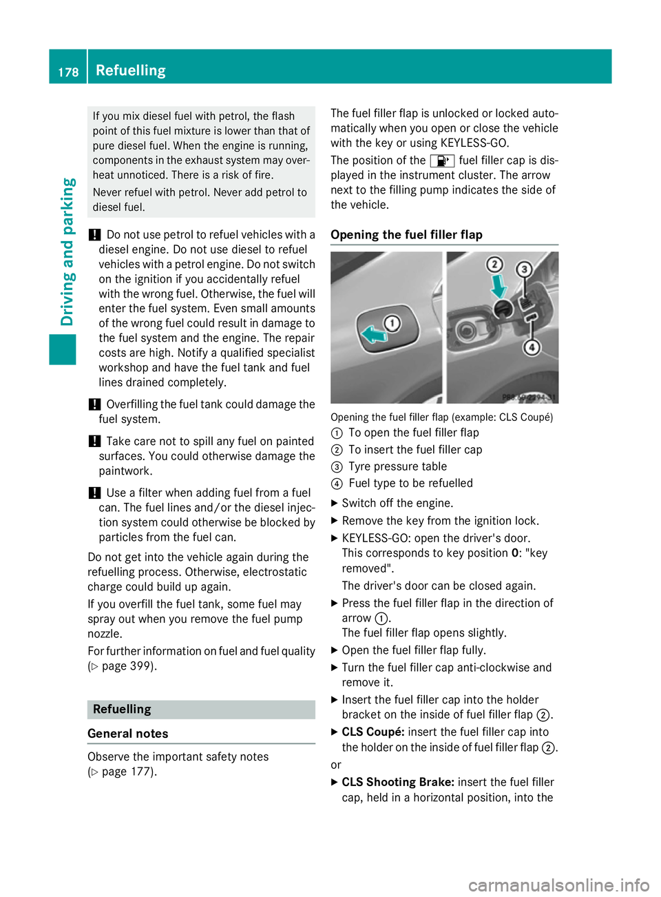
Opening the fuel filler flap Opening the fuel filler flap (example: CLS Coupé)
:
To open the fuel filler flap
; To insert the fuel filler cap
= Tyre pressure table
? Fuel type to be refuelled
X Switch off the engine.
X Remove the key from the ignition lock.
X KEYLESS-GO: open the driver's door.
This corresponds to key position 0: "key
removed".
The driver's door can be closed again.
X Press the fuel filler flap in the direction of
arrow :.
The fuel filler flap opens slightly.
X Open the fuel filler flap fully.
X Turn the fuel filler cap anti-clockwise and
remove it.
X Insert the fuel filler cap into the holder
bracket on the inside of fuel filler flap ;.
X CLS Coupé: insert the fuel filler cap into
the holder on the inside of fuel filler flap ;.
or
X CLS Shooting Brake: insert the fuel filler
cap, held in a horizontal position, into the 178
RefuellingDriving and parking
Page 182 of 417
recesses in the fuel filler flap hinge arm
from above.
X Completely insert the filler neck of the fuel
pump nozzle into the tank, hook in place
and refuel.
X Only fill the tank until the pump nozzle
switches off.
i Vehicles with a diesel engine: the filler
neck is designed for refuelling at diesel fill-
ing pumps.
i Do not add any more fuel after the pump
stops filling for the first time. Otherwise,
fuel may leak out.
Closing the fuel filler flap X
Replace the cap on the filler neck and turn
clockwise until it engages audibly.
X Close the fuel filler flap.
i Close the fuel filler flap before locking the
vehicle. Otherwise, the locking pin of the
central locking prevents the fuel filler flap
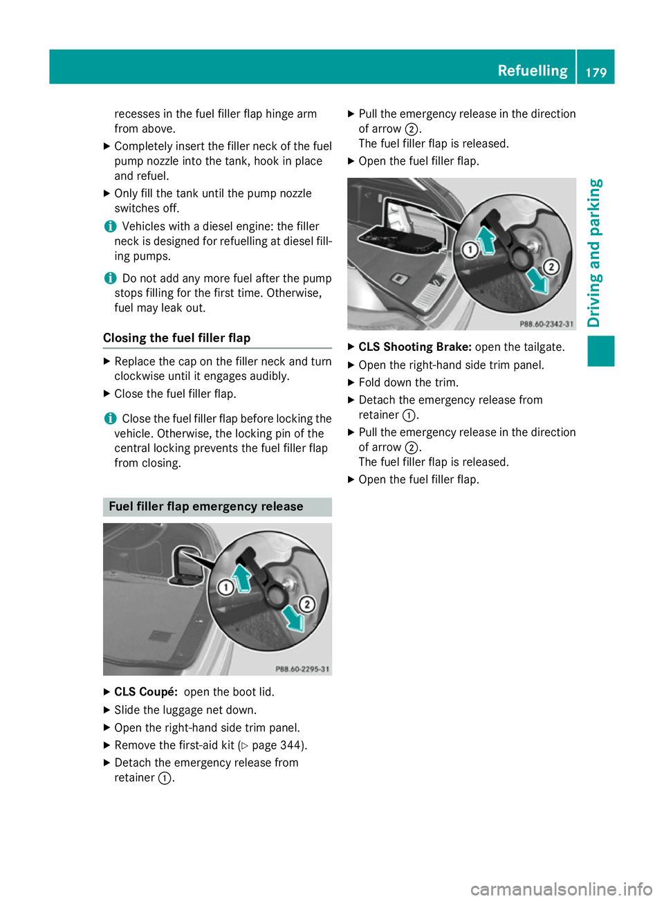
from closing. Fuel filler flap emergency release
X
CLS Coupé: open the boot lid.
X Slide the luggage net down.
X Open the right-hand side trim panel.
X Remove the first-aid kit (Y page 344).
X Detach the emergency release from
retainer :. X
Pull the emergency release in the direction
of arrow ;.
The fuel filler flap is released.
X Open the fuel filler flap. X
CLS Shooting Brake: open the tailgate.
X Open the right-hand side trim panel.
X Fold down the trim.
X Detach the emergency release from
retainer :.
X Pull the emergency release in the direction
of arrow ;.
The fuel filler flap is released.
X Open the fuel filler flap. Refuelling
179Driving and parking Z
Page 205 of 417
R
the vehicle is stationary and the brake
pedal is depressed (left foot)
R the transmission is in position D
Activating RACE START X
Depress the brake pedal with your left foot
and keep it depressed.
X Turn the drive program selector clockwise
(Y page 172) until the RSlamp lights up.
The RACE START Confirm: Paddle UP
RACE START Confirm: Paddle UP
Cancel: Paddle DOWN Cancel: Paddle DOWN message appears
in the multifunction display.
i If the activation conditions are no longer
fulfilled, RACE START is cancelled. The
RACE
RACE START
START cancelled
cancelled message appears
in the multifunction display.
X To cancel: pull the left steering wheel shift
paddle (Y page 173).
or
X To confirm: pull the right steering wheel
shift paddle (Y page 173).
The RACE START available Depress
RACE START available Depress
accelerator
accelerator message appears in the mul-
tifunction display.
i If you do not depress the accelerator
pedal fully within two seconds, RACE
START is cancelled. The RACE
RACE START
START not
not
possible
possible See
SeeOwner's
Owner's Manual
Manualmessage
appears in the multifunction display.
X Fully depress the accelerator pedal.
The engine speed rises to approximately
3,500 rpm.
The RACE START Release brake to
RACE START Release brake to
start start message appears in the multifunc-
tion display.
i If you do not release the brake pedal
within five seconds, RACE START is cancel-
led. The RACE
RACESTART
START cancelled
cancelled message
appears in the multifunction display.
X Take your foot off the brake, but keep the
accelerator pedal depressed.
The vehicle pulls away at maximum accel-
eration. The
RACE RACE START
START active
active message appears
in the multifunction display.
RACE START is deactivated when the vehicle
reaches a speed of approximately 50 km/h.
Drive program S+is activated. SPORT han-
dling mode remains activated.
RACE START is deactivated immediately if
you release the accelerator pedal during
RACE START or if any of the activation condi- tions are no longer fulfilled. The RACE
RACE START START
not possible See Owner's Manual
not possible See Owner's Manual mes-
sage appears in the multifunction display.
i After using it several times in short suc-
cession, RACE START will be unavailable
until a certain distance has been driven. AIRMATIC
Vehicle level Important safety notes
G
WARNING
People's limbs may become trapped if they
are located underneath the vehicle or
between the vehicle body and the tyres when the vehicle is lowering. There is a danger of
injury.
When lowering the vehicle, make sure no one
is underneath the vehicle or in the immediate vicinity of the wheel arches. G
WARNING
Vehicles with level control:
The vehicle is slightly lowered if you:
R have selected comfort suspension tuning
and
R you lock the vehicle within approximately
60 second s of switching off the engine
You and people in the vicinity of the wheel
arch or the underbody may thus become trap- ped. There is a risk of injury.
Make sure that nobody is in the vicinity of thewheel arch or the underbody when you lock
the vehicle. 202
Driving systemsDriving and parking
Page 237 of 417
prescribed maximum speed in the relevant
country.
For certain Mercedes-Benz vehicles, the max-
imum permissible rear axle load is increased
when towing a trailer. See "Technical data" to
find out whether this applies to your vehicle
(Y page 410). If you utilise any of the added
maximum rear axle load when towing a trailer, the vehicle/trailer combination may not
exceed a maximum speed of 100 km/ hfor
reasons concerning the operating permit.
This also applies in countries in which the
permissible maximum speed for vehicle/
trailer combinations is above 100 km/h.
When towing a trailer, your vehicle's handling
characteristics will be different in comparison
to when driving without a trailer and it will
consume more fuel.
Change into a lower gear in good time on long and steep downhill gradients.
i This also applies if you have activated
cruise control, SPEEDTRONIC or DIS-
TRONIC PLUS.
This will use the braking effect of the engine,
so less braking will be required to maintain
vehicle speed. This relieves the load on the
brake system and prevents the brakes from
overheating and wearing too quickly. If you
need additional braking, depress the brake
pedal repeatedly rather than continuously.
Driving tips If the trailer swings from side to side:
X Do not accelerate.
X Do not countersteer.
X Brake if necessary.
R Maintain a greater distance from the vehi-
cle in front than when driving without a
trailer.
R Avoid braking abruptly. If possible, brake
gently at first to allow the trailer to run on. Then, increase the braking force rapidly.
R The values given for gradient-climbing
capabilities from a standstill refer to sea level. When driving in mountainous areas,
note that the power output of the engine,
and consequently the vehicle's gradient-
climbing capability, decrease with increas-
ing altitude. Folding out the ball coupling
G
WARNING
If the ball coupling is not correctly engaged,
the trailer can detach. There is a risk of an
accident.
Always engage the ball coupling as described. G
WARNING
If you release the ball coupling or it does not
engage correctly when folding in, it will swing out. Within pivoting range of the ball coupling,
there is an increased risk of an accident and
injury.
Only release the ball coupling if the pivoting
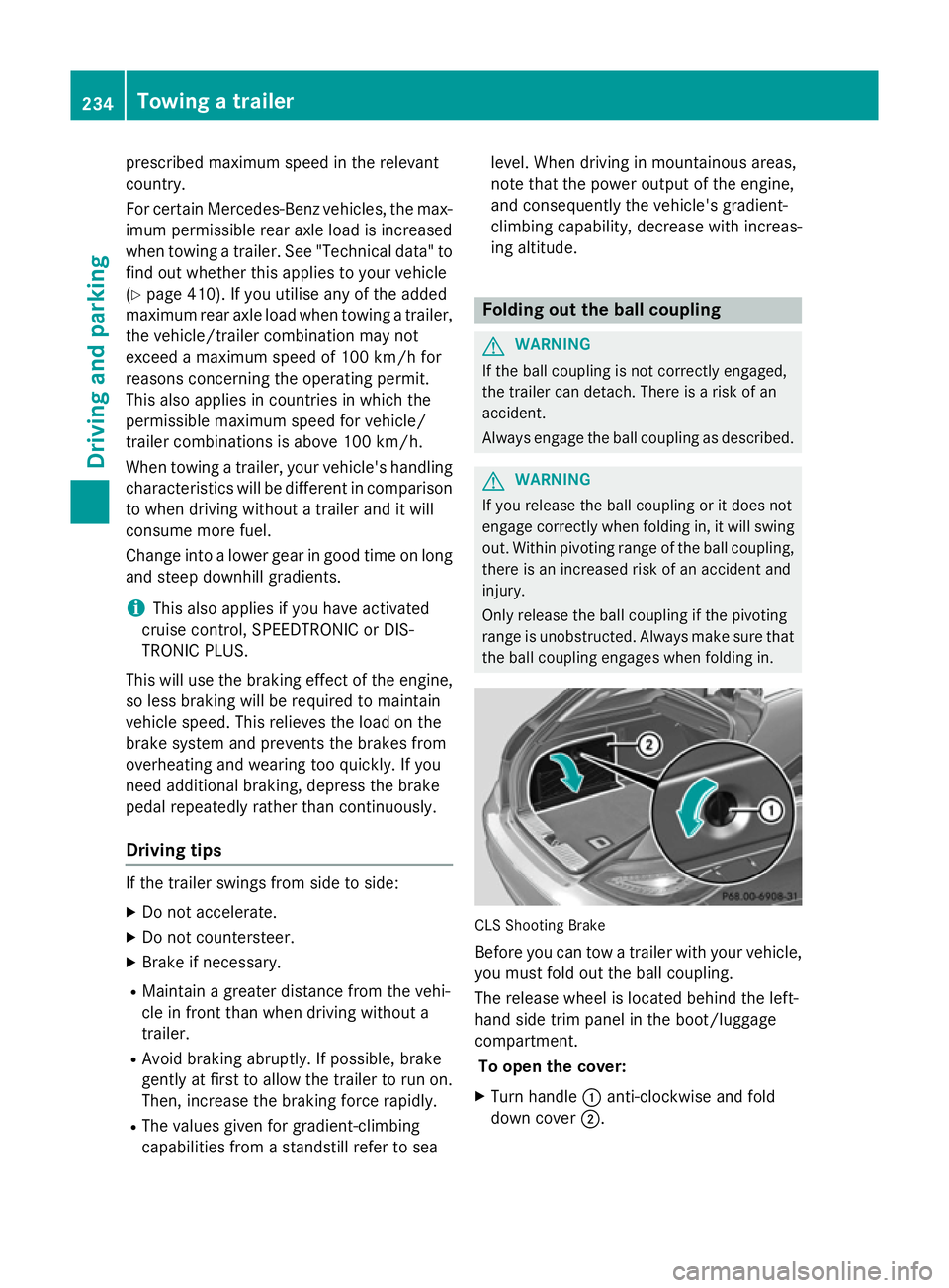
range is unobstructed. Always make sure that the ball coupling engages when folding in. CLS Shooting Brake
Before you can tow a trailer with your vehicle, you must fold out the ball coupling.
The release wheel is located behind the left-
hand side trim panel in the boot/luggage
compartment.
To open the cover:
X Turn handle :anti-clockwise and fold
down cover ;.234
Towing a trailerDriving and parking
Page 238 of 417
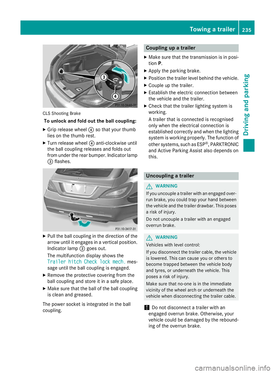
CLS Shooting Brake
To unlock and fold out the ball coupling:
X Grip release wheel ?so that your thumb
lies on the thumb rest.
X Turn release wheel ?anti-clockwise until
the ball coupling releases and folds out
from under the rear bumper. Indicator lamp = flashes. X
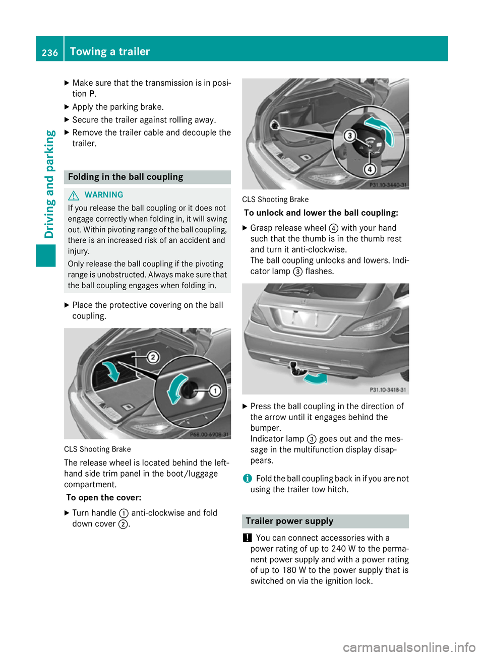
Pull the ball coupling in the direction of the
arrow until it engages in a vertical position.
Indicator lamp =goes out.
The multifunction display shows the
Trailer
Trailer hitch hitchCheck
Checklock
lockmech.
mech. mes-
sage until the ball coupling is engaged.
X Remove the protective covering from the
ball coupling and store it in a safe place.
X Make sure that the ball of the ball coupling
is clean and greased.
The power socket is integrated in the ball
coupling. Coupling up a trailer
X Make sure that the transmission is in posi-
tion P.
X Apply the parking brake.
X Position the trailer level behind the vehicle.
X Couple up the trailer.
X Establish the electric connection between
the vehicle and the trailer.
X Check that the trailer lighting system is
working.
A trailer that is connected is recognised
only when the electrical connection is
established correctly and when the lighting
system is working properly. The function of
other systems, such as ESP ®
, PARKTRONIC
and Active Parking Assist also depends on
this. Uncoupling a trailer
G
WARNING
If you uncouple a trailer with an engaged over- run brake, you could trap your hand between
the vehicle and the trailer drawbar. This poses a risk of injury.
Do not uncouple a trailer with an engaged
overrun brake. G
WARNING
Vehicles with level control:
If you disconnect the trailer cable, the vehicle is lowered. This can cause you or others to
become trapped between the vehicle body
and tyres, or underneath the vehicle. This
poses a risk of injury.
Make sure that no-one is in the immediate
vicinity of the wheel arch or underneath the
vehicle when disconnecting the trailer cable.
! Do not disconnect a trailer with an
engaged overrun brake. Otherwise, your
vehicle could be damaged by the rebound- ing of the overrun brake. Towing a trailer
235Driving and parking Z
Page 239 of 417
X
Make sure that the transmission is in posi-
tion P.
X Apply the parking brake.
X Secure the trailer against rolling away.
X Remove the trailer cable and decouple the
trailer. Folding in the ball coupling
G
WARNING
If you release the ball coupling or it does not
engage correctly when folding in, it will swing out. Within pivoting range of the ball coupling,
there is an increased risk of an accident and
injury.
Only release the ball coupling if the pivoting
range is unobstructed. Always make sure that the ball coupling engages when folding in.
X Place the protective covering on the ball
coupling. CLS Shooting Brake
The release wheel is located behind the left-
hand side trim panel in the boot/luggage
compartment.
To open the cover:
X Turn handle :anti-clockwise and fold
down cover ;. CLS Shooting Brake
To unlock and lower the ball coupling:
X Grasp release wheel ?with your hand
such that the thumb is in the thumb rest
and turn it anti-clockwise.
The ball coupling unlocks and lowers. Indi-
cator lamp =flashes. X
Press the ball coupling in the direction of
the arrow until it engages behind the
bumper.
Indicator lamp =goes out and the mes-
sage in the multifunction display disap-
pears.
i Fold the ball coupling back in if you are not
using the trailer tow hitch. Trailer power supply
! You can connect accessories with a
power rating of up to 240 W to the perma-
nent power supply and with a power rating of up to 180 W to the power supply that is
switched on via the ignition lock. 236
Towing a trailerDriving and parking
Page 240 of 417
The trailer battery may not be charged from
the power supply.
X To switch the connected power supply
on or off: turn the key in the ignition lock to
position 2or 0respectively (Y page 159).
When it leaves the factory, your vehicle's
trailer socket is equipped with a permanent
power supply and a power supply that is
switched on via the ignition lock.
The permanent power supply is supplied via
trailer socket pin 9.
The power supply that is switched on via the
ignition lock is supplied via trailer socket pin
10.
The trailer's permanent power supply is
switched off in the event of low vehicle supply
voltage and after six hours at the latest.
You can find more information about instal-
ling the trailer electrics at a qualified special- ist workshop. Bulb failure indicator for LED lamps
i If LED lamps are fitted in the trailer, an
error message may appear in the multi-
function display even if there is no fault. The reason for the error message could be that
the current has fallen below the minimum
of 50 mA.
To ensure reliable operation of the bulb failure indicator, each LED chain in the trailer lighting
must be guaranteed a minimum current of
50 mA. Trailer with 7-pin connector
General notes Trailer with 7-pin connector:
you can con-
nect to the 13-pin socket on the ball coupling
using an adapter or, if necessary, an adapter
cable. Both can be obtained at a qualified
specialist workshop. Fitting the adapter !
Make sure that there is sufficient cable
play so that the cable cannot become
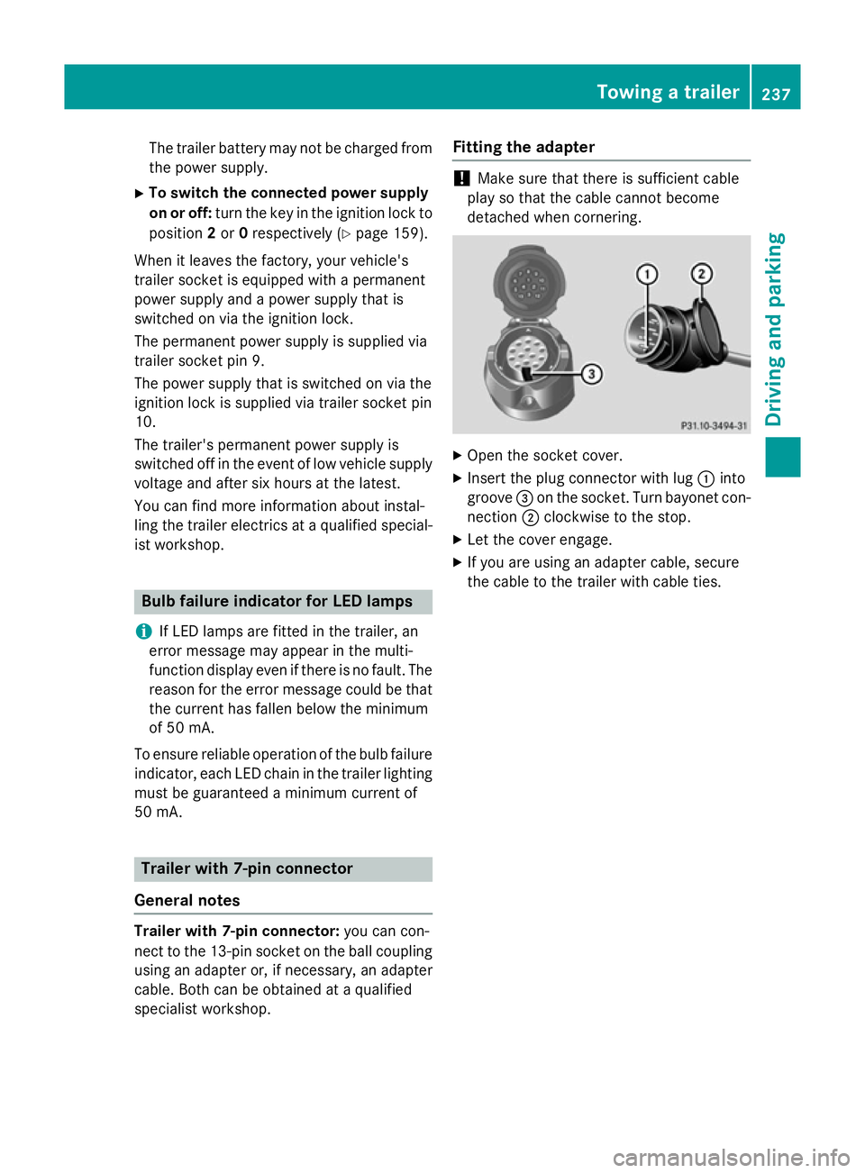
detached when cornering. X
Open the socket cover.
X Insert the plug connector with lug :into
groove =on the socket. Turn bayonet con-
nection ;clockwise to the stop.
X Let the cover engage.
X If you are using an adapter cable, secure
the cable to the trailer with cable ties. Towing a trailer
237Driving and parking Z
Page 258 of 417
X
Press the =or; button on the steer-
ing wheel to select the Settings Settingsmenu.
X Press the :or9 button to select the
Light
Light submenu.
X Press ato confirm.
X Press the :or9 button to select the
Light. delay Light. delay function.
If the Light. delay
Light. delay function has been
switched on, the vehicle interior is dis-
played in orange in the multifunction dis-
play.
X Press the abutton to save the setting.
Vehicle Setting permanent SPEEDTRONIC
X Press the =or; button on the steer-
ing wheel to select the Settings Settingsmenu.
X Press the :or9 button to select the
Vehicle
Vehicle submenu.
X Press ato confirm.
X Press :or9 to select the Limit
Limit
speed (winter tyres):
speed (winter tyres): function.
You will see the current setting.
X Press ato confirm.
X Press the :or9 button to adjust
permanent SPEEDTRONIC in increments of
ten (230 km/h 230 km/h to160 km/h
160 km/h). The Off
Offset-
ting switches permanent SPEEDTRONIC
off.
X Press the abutton to store the entry.
For further information on permanent SPEED- TRONIC (Y page 191).
Switching the automatic locking feature
on/off
X Press the =or; button on the steer-
ing wheel to select the Settings Settingsmenu.
X Press the :or9 button to select the
Vehicle
Vehicle submenu.
X Press ato confirm.
X Press the :or9 button to select the
Auto. door locks
Auto. door locks function.
When the Auto. door locks
Auto. door locks function is
switched on, the vehicle doors are dis- played in orange in the multifunction dis-
play.
X Press the abutton to save the setting.
If you activate the Auto. door locks Auto. door locks func-
tion, the vehicle is centrally locked above a
speed of around 15 km/h.
Further information on the automatic locking feature (Y page 90).
Activating/deactivating the acoustic
locking confirmation
If you switch on the Acoustic AcousticLock
Lockfunction,
an acoustic signal sounds when you lock the
vehicle.
X Press the =or; button on the steer-
ing wheel to select the Settings
Settingsmenu.
X Press the :or9 button to select the
Vehicle
Vehicle submenu.
X Press ato confirm.
X Press the :or9 button to select the
Acoustic Lock
Acoustic Lock function.
If the Acoustic
Acoustic Lock
Lockfunction is activated,
the & symbol in the multifunction dis-
play lights up orange.
X Press the abutton to save the setting.
Activating/deactivating the radar sensor
system X Press the =or; button on the steer-
ing wheel to select the Settings Settingsmenu.
X Press the :or9 button to select the
Vehicle
Vehicle submenu.
X Press ato confirm.
X Press the 9or: button to select
Radar sensor (See Owner's Man.):
Radar sensor (See Owner's Man.):.
You will see the selected setting: on onoroff
off.
X Press the abutton to save the setting.
The following systems are switched off when
the radar sensor system is deactivated:
R DISTRONIC PLUS (Y page 191)
R BAS PLUS (Y page 71)
R PRE-SAFE ®
Brake (Y page 76)
R Blind Spot Assist (Y page 223)
R Active Blind Spot Assist (Y page 227) Menus and submenus
255On-board computer and displays Z