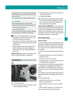
Page 425 of 489

Fitting/removing the towing eye
Fitting the towing eye The brackets for the screw-in towing eyes are
located in the bumpers. They are at the rear
and at the front, under covers :.
X Remove the towing eye from the vehicle
tool kit/stowage tray (Y page 407).
X Press the mark on cover :inwards and
remove.
X Screw the towing eye in clockwise to the
stop and tighten it.
Vehicles with a trailer tow hitch do not have a
bracket at the back for the screw-in towing
eye. Connect the towbar to the trailer tow
hitch (Y page 284).
Removing the towing eye X
Loosen the towing eye and unscrew it.
X Attach cover :to the bumper and press
until it engages.
X Place the towing eye in the vehicle tool kit/
stowage tray. Towing the vehicle away with the rear
axle raised
Hybrid vehicles: towing the vehicle with the
rear axle raised should only be carried out by
professional recovery companies.
Only vehicles without 4MATIC can be
towed with the rear axle raised.
! Vehicles with 4MATIC must not be towed
with the front or rear axle raised; otherwise, the transmission may be damaged.
Vehicles with 4MATIC may either be towed
away with both axles on the ground or be loa-
ded up and transported.
! The ignition must be switched off if you
are towing the vehicle with the rear axle
raised. Intervention by ESP ®
could other-
wise damage the brake system.
X Switch on the hazard warning lamps
(Y page 137).
X Move the front wheels to the straight-
ahead position.
X If necessary, turn the key in the ignition
lock to position 0and remove the key from
the ignition lock.
X When leaving the vehicle, take the key with
you.
When towing your vehicle with the rear axle
raised, it is important that you observe the
safety instructions (Y page 420). Towing the vehicle with both axles on
the ground
Hybrid vehicles: hybrid vehicles may not be
towed away with both axles on the ground if:
R the multifunction display is not working or
R the multifunction display shows the ~
Malfunction Malfunction or
R d Malfunction Malfunction is displayed
If the vehicle is in a dangerous location it may
be towed from the danger zone with both
axles on the ground. In this case, the towing
distance may not be greater than 50 m and 422
Towing away and tow-startingBreakdown assistance
Page 426 of 489

the towing speed must not exceed 10 km/h.
For longer distances, have the vehicle loaded
and transported or towed with the rear axle
raised.
Vehicles with automatic transmission: the
automatic transmission automatically shifts
to position Pwhen you open the driver's or
front-passenger door or when you remove the
key from the ignition lock. In order to ensure that the automatic transmission stays in posi- tion Nwhen towing the vehicle, you must
observe the following points:
X Make sure that the vehicle is stationary.
X Turn the key to position 2in the ignition
lock.
X Depress and hold the brake pedal.
X Shift the automatic transmission to posi-
tion N.
Vehicles with manual transmission:
X Turn the key to position 2in the ignition
lock.
X Depress and hold the brake pedal.
X Depress the clutch pedal fully and shift to
neutral.
Vehicles with manual or automatic trans- mission:
X Leave the key in position 2in the ignition
lock.
X Release the brake pedal.
X Release the electric parking brake.
X Switch on the hazard warning lamps
(Y page 137).
In order to signal a change of direction when towing the vehicle with the hazard warning
lamps switched on, use the combination
switch as usual. In this case, only the turn
signals for the desired direction flash. When
you reset the combination switch, the hazard
warning lamps start flashing again. Transporting the vehicle
Hybrid vehicles: transportation of the vehi-
cle should only be carried out by professional
recovery companies.
! You may only secure the vehicle by the
wheels, not by parts of the vehicle such as
axle or steering components. Otherwise,
the vehicle could be damaged.
The towing eyes or trailer tow hitch can be
used to pull the vehicle onto a trailer or trans-
porter if you wish to transport it.
X Vehicles with manual transmission:
depress the clutch pedal fully and shift to
neutral.
X Vehicles with automatic transmission:
turn the key to position 2in the ignition
lock.
X Shift the automatic transmission to posi-
tion N.
As soon as the vehicle is loaded: X Prevent the vehicle from rolling away by
applying the electric parking brake.
X Vehicles with manual transmission:
depress the clutch pedal fully and engage
first or reverse gear.
X Vehicles with automatic transmission:
shift the automatic transmission to posi-
tion P.
X Turn the key to position 0in the ignition
lock and remove it.
X Secure the vehicle. Notes for 4MATIC vehicles
! Vehicles with 4MATIC must not be towed
with the front or rear axle raised; otherwise,
the transmission may be damaged.
Vehicles with 4MATIC may either be towed
away with both axles on the ground or be loa- ded up and transported.
If the vehicle has transmission damage or
damage to the front or rear axle, have it trans-
ported on a transporter or trailer. Towing away and tow-starting
423Breakdown assistance Z
Page 427 of 489

In the event of damage to the electrical
system: if the battery is defective, the auto-
matic transmission will be locked in position
P. To shift the automatic transmission to posi-
tion N, you must provide power to the vehi-
cle's electrical system in the same way as
when jump-starting (Y page 418).
Have the vehicle transported on a transporter
or trailer. Tow-starting (emergency engine
starting)
! Do not tow-start vehicles with automatic
transmission. You could otherwise damage the automatic transmission.
i You can find information on "Jump-start-
ing" under (Y page 418).
Before tow-starting, the following conditions
must be fulfilled:
R the battery is connected
R the engine has cooled down
R the exhaust system has cooled down
When tow-starting, it is important that you
observe the safety notes (Y page 420) and the
legal requirements in each respective coun-
try.
X Switch on the hazard warning lamps
(Y page 137).
X Fit the towing eye (Y page 422).
X Secure the rigid towing bar or the towing
rope.
X Depress and hold the brake pedal.
X Turn the key to position 2in the ignition
lock.
X Depress the clutch pedal fully, engage sec-
ond gear and continue to keep the clutch
pedal fully depressed.
X Release the brake pedal.
X Tow-start the vehicle.
X Release the clutch pedal slowly; do not
depress the accelerator pedal while doing
so. X
When the engine has been started, imme-
diately depress the clutch pedal fully and
shift to neutral.
X Pull over at a suitable place and stop the
vehicle safely, paying attention to road and
traffic conditions.
X Use the electric parking brake to secure the
vehicle and prevent it from rolling away.
X Remove the rigid towing bar or towing rope.
X Remove the towing eye (Y page 422).
X Switch off the hazard warning lamps. Electrical fuses
Important safety notes
G
WARNING
If you manipulate, bridge or replace a faulty
fuse with a fuse of a higher amperage, the
electric cables could be overloaded. This may result in a fire. There is a risk of an accident
and injury.
Always replace faulty fuses with specified new fuses of the correct amperage.
Blown fuses must be replaced with fuses of
the same rating, which you can recognise by
the colour and fuse rating. The fuse ratings
are listed in the fuse allocation chart.
If the newly inserted fuse also blows, have the
cause traced and rectified at a qualified spe-
cialist workshop, e.g. a Mercedes-Benz Ser-
vice Centre.
! Only use fuses that have been approved
for Mercedes-Benz vehicles and which
have the correct fuse rating for the system concerned. Otherwise, components or sys-
tems could be damaged.
The fuses in your vehicle disconnect faulty
circuits. If a fuse blows, all the components on the circuit and their functions will fail. 424
Electrical fusesBreakdown assistance
Page 428 of 489

Before replacing a fuse
X Secure the vehicle against rolling away
(Y page 207).
X Switch off all electrical consumers.
X Make sure that the ignition is switched off
(Y page 181).
or
X When using the key, turn the key to position
0 in the ignition lock and remove it
(Y page 181).
All indicator lamps in the instrument cluster
must be off.
The fuses are located in various fuse boxes:
R fuse box on the driver's side of the dash-
board
R fuse box in the front-passenger footwell
R fuse box in the engine compartment on the
driver's side
R fuse box under the boot floor on the right-
hand side of the vehicle, when viewed in the
direction of travel
The fuse allocation chart is on the fuse box in
the boot (Y page 426). Dashboard fuse box
! Do not use a pointed object such as a
screwdriver to open the cover in the dash-
board. You could damage the dashboard or
the cover.
! Make sure that no moisture can enter the
fuse box when the cover is open.
! When closing the cover, make sure that it
is lying correctly on the fuse box. Moisture seeping in or dirt could otherwise impair
the operation of the fuses. X
Open the driver's door.
X To open: pull out cover :slightly at the
bottom in the direction of arrow =.
X Fold cover :outwards in the direction of
arrow ;.
X To close: fold in cover :until it engages. Fuse box in the front-passenger foot-
well
! Make sure that no moisture can enter the
fuse box when the cover is open.
! When closing the cover, make sure that it
is lying correctly on the fuse box. Moisture seeping in or dirt could otherwise impair
the operation of the fuses.
X Open the front-passenger door. X
Open the front-passenger door.
X To open: fold cover :out towards the rear
and remove it.
X To close: clip in cover :at the rear.
X Fold cover :forwards until it engages. Electrical fuses
425Breakdown assis tance Z
Page 429 of 489

Fuse box in the engine compartment
G
WARNING
When the bonnet is open, and the windscreen wipers are set in motion, you can be injured by
the wiper linkage. There is a risk of injury.
Always switch off the windscreen wipers and
the ignition before opening the bonnet.
! Make sure that no moisture can enter the
fuse box when the cover is open.
! When closing the cover, make sure that it
is lying correctly on the fuse box. Moisture
seeping in or dirt could otherwise impair
the operation of the fuses. X
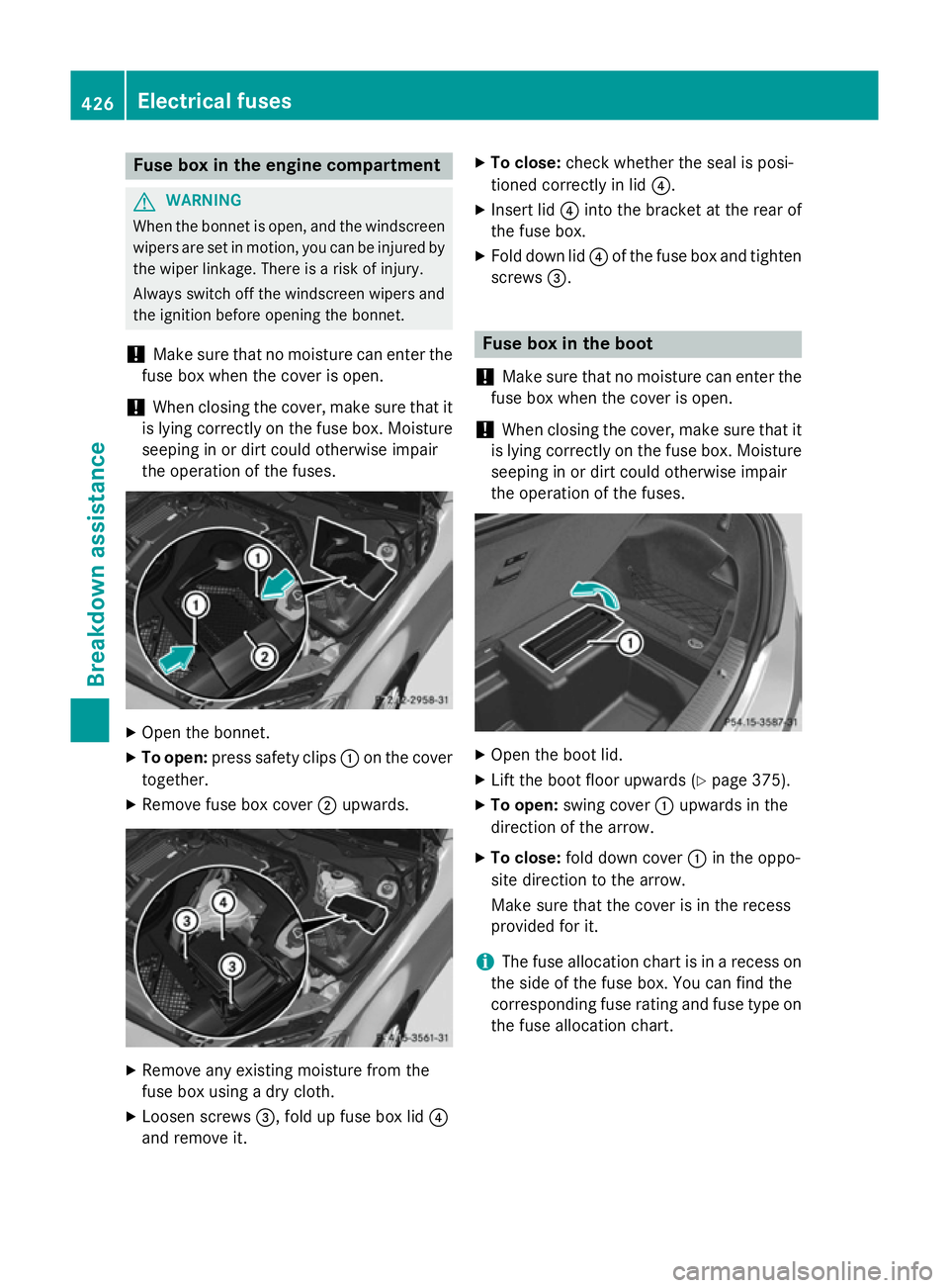
Open the bonnet.
X To open: press safety clips :on the cover
together.
X Remove fuse box cover ;upwards. X
Remove any existing moisture from the
fuse box using a dry cloth.
X Loosen screws =, fold up fuse box lid ?
and remove it. X
To close: check whether the seal is posi-
tioned correctly in lid ?.
X Insert lid ?into the bracket at the rear of
the fuse box.
X Fold down lid ?of the fuse box and tighten
screws =. Fuse box in the boot
! Make sure that no moisture can enter the
fuse box when the cover is open.
! When closing the cover, make sure that it
is lying correctly on the fuse box. Moisture seeping in or dirt could otherwise impair
the operation of the fuses. X
Open the boot lid.
X Lift the boot floor upwards (Y page 375).
X To open: swing cover :upwards in the
direction of the arrow.
X To close: fold down cover :in the oppo-
site direction to the arrow.
Make sure that the cover is in the recess
provided for it.
i The fuse allocation chart is in a recess on
the side of the fuse box. You can find the
corresponding fuse rating and fuse type on the fuse allocation chart. 426
Electrical fusesBreakdown assistance
Page 430 of 489
Useful information
............................428
Important safety notes .....................428
Operation ........................................... 428
Winter operation ............................... 430
Tyre pressure .................................... 432
Changing a wheel .............................. 437
Wheel and tyre combinations ..........444
Emergency spare wheel ...................461 427Wheels and tyres
Page 431 of 489

Useful information
i This Owner's Manual describes all mod-
els, series and optional equipment for your
vehicle that were available at the time of
going to press. National variations are pos- sible. Note that your vehicle may not be
equipped with all of the functions descri-
bed. This is also the case for systems and
functions relevant to safety.
i Read the information on qualified special-
ist workshops: (Y page 27). Important safety notes
G
WARNING
If wheels and tyres of the wrong size are used, the wheel brakes or suspension components
may be damaged. There is a risk of an acci-
dent.
Always replace wheels and tyres with those
that fulfil the specifications of the original
part.
When replacing wheels, make sure to fit the
correct:
R designation
R type
When replacing tyres, make sure to fit the
correct:
R designation
R manufacturer
R type G
WARNING
A flat tyre severely impairs the driving, steer-
ing and braking characteristics of the vehicle.
There is a risk of accident.
Tyres without run-flat characteristics:
R do not drive with a flat tyre.
R immediately replace the flat tyre with your
emergency spare wheel or spare wheel, or
consult a qualified specialist workshop. Tyres with run-flat characteristics:
R pay attention to the information and warn-
ing notices on MOExtended tyres (tyres
with run-flat characteristics).
Accessories that are not approved for your
vehicle by Mercedes-Benz or are not being
used correctly can impair the operating
safety.
Before purchasing and using non-approved
accessories, visit a qualified specialist work-
shop and enquire about:
R suitability
R legal stipulations
R factory recommendations
Information on the dimensions and types of
wheels and tyres for your vehicle can be
found under "Wheel/tyre combinations"
(Y page 444).
Information on air pressure for the tyres on
your vehicle can be found:
R on the tyre pressure label on the fuel filler
flap (Y page 202)
R under "Tyre pressure" (Y page 432)
Modification work on the brake system and
wheels is not permitted. The use of wheel
spacers or brake dust shields is not permit-
ted. This invalidates the general operating
permit for the vehicle.
i Further information on wheels and tyres
can be obtained at any qualified specialist
workshop. Operation
Information on driving
Check the tyre pressures when the vehicle is
heavily laden and, if necessary, adjust.
While driving, pay attention to vibrations,
noises and unusual handling characteristics,
e.g. pulling to one side. This may indicate that the wheels or tyres are damaged. If you sus-
pect that a tyre is defective, reduce your
speed immediately. Stop the vehicle as soon 428
OperationWheels and tyres
Page 432 of 489

as possible to check the wheels and tyres for
damage. Hidden tyre damage could also be
causing the unusual handling characteristics.
If you find no signs of damage, have the tyres and wheels checked at a qualified specialist
workshop.
When parking your vehicle, make sure that
the tyres do not get deformed by the kerb or
other obstacles. If it is necessary to drive over
kerbs, speed humps or similar elevations, try
to do so slowly and at an obtuse angle. Oth-
erwise, the tyres, particularly the sidewalls,
may be damaged. Regular checking of wheels and tyres
G
WARNING
Damaged tyres can cause tyre inflation pres-
sure loss. As a result, you could lose control of your vehicle. There is a risk of accident.
Check the tyres regularly for signs of damage and replace any damaged tyres immediately.
Regularly check the wheels and tyres of your
vehicle for damage at least once a month, as well as after driving off-road or on rough
roads. Damaged wheels can cause a loss of
tyre pressure. Pay particular attention to
damage such as:
R cuts in the tyres
R punctures
R tears in the tyres
R bulges on the tyres
R deformation or severe corrosion on wheels
Regularly check the tyre tread depth and the condition of the tread across the whole width
of the tyre (Y page 429). If necessary, turn
the front wheels to full lock in order to inspect
the inner side of the tyre surface.
All wheels must have a valve cap to protect
the valve against dirt and moisture. Do not fit
anything onto the valve other than the stand-
ard valve cap or other valve caps approved for
your vehicle by Mercedes-Benz. Do not fit any other valve caps or systems, e.g. tyre pres-
sure monitoring systems.
Regularly check the pressure of all the tyres,
particularly prior to long trips. Adjust the tyre
pressure as necessary (Y page 432).
Observe the notes on the emergency spare
wheel (Y page 461).
The service life of tyres depends on various
factors, including the following:
R driving style
R tyre pressure
R mileage Important safety notes on the tyre
tread
G
WARNING
Insufficient tyre tread will reduce tyre trac-
tion. The tyre is no longer able to dissipate
water. This means that on wet road surfaces, the risk of aquaplaning increases, in particularwhere speed is not adapted to suit the driving
conditions. There is a risk of accident.
If the tyre pressure is too high or too low, tyres may exhibit different levels of wear at differ-
ent locations on the tyre tread. Thus, you
should regularly check the tread depth and
the condition of the tread across the entire
width of all tyres.
Minimum tyre tread depth for:
R summer tyres: 3 mm
R M+S tyres: 4 mm
For safety reasons, replace the tyres before
the legally prescribed limit for the minimum
tyre tread depth is reached. Selecting, fitting and replacing tyres
G
WARNING
Exceeding the stated tyre load-bearing capa-
city and the approved maximum speed could
lead to tyre damage or the tyre bursting. There is a risk of accident. Operation
429Wheels and tyres
Z