2014 MERCEDES-BENZ C-CLASS ESTATE light
[x] Cancel search: lightPage 440 of 489
Use a suitable pressure gauge to check the
tyre pressure. The outer appearance of a tyre does not permit any reliable conclusion aboutthe tyre pressure. On vehicles fitted with the
electronic tyre pressure monitor, the tyre
pressure can be checked using the on-board
computer.
If possible, only correct tyre pressures when
the tyres are cold.
The tyres are cold:
R if the vehicle has been parked with the tyres
out of direct sunlight for at least three
hours and
R if the vehicle has not been driven further
than 1.6 km
Depending on the ambient temperature, the
speed at which you are driving and the load on the tyres, the tyre temperature and thus the
tyre pressure changes by approximately
10 kPa (0.1 bar/1.5 psi) per 10 †. Take this
into account when checking the pressure of
warm tyres. Only correct the tyre pressure if it
is too low for the current operating condi-
tions.
Driving with tyre pressure that is too high or
too low can:
R shorten the service life of the tyres
R cause increased tyre damage
R have a negative effect on handling charac-
teristics and thus driving safety (e.g. aqua-
planing)
The tyre pressure values given for low loads
are minimum values which offer you good ride
comfort characteristics.
However, you can also use the values given
for higher loads. These are permissible and
will not adversely affect the running of the
vehicle. For Saloons at speeds of up to 210 km/h
(does not apply to AMG vehicles, AMG
Sport models): despite what is stated on the
tyre pressure information label (fuel filler
flap), at speeds of up to 210 km/h the values stated can be reduced as follows, without a
reduction in safety:
R Saloons (except Eco models): Ò30 kPa
(Ò0.3 bar/ Ò4 psi)
R Saloons (Eco models with 16 or 17 in
tyres on both axles): Ò60 kPa (Ò0.6 bar/
Ò9 psi)
This does not apply to vehicles towing a
trailer.
This improves the ride comfort of your vehi-
cle; however, fuel consumption may increase slightly. Tyre pressure monitor
General notes If a tyre pressure monitor system is fitted, the
vehicle's wheels have sensors fitted that
monitor the tyre pressures in all four tyres.
The tyre pressure monitor warns you if the
pressure drops in one or more of the tyres.
The tyre pressure monitor only functions if
the corresponding sensors are fitted to all
wheels.
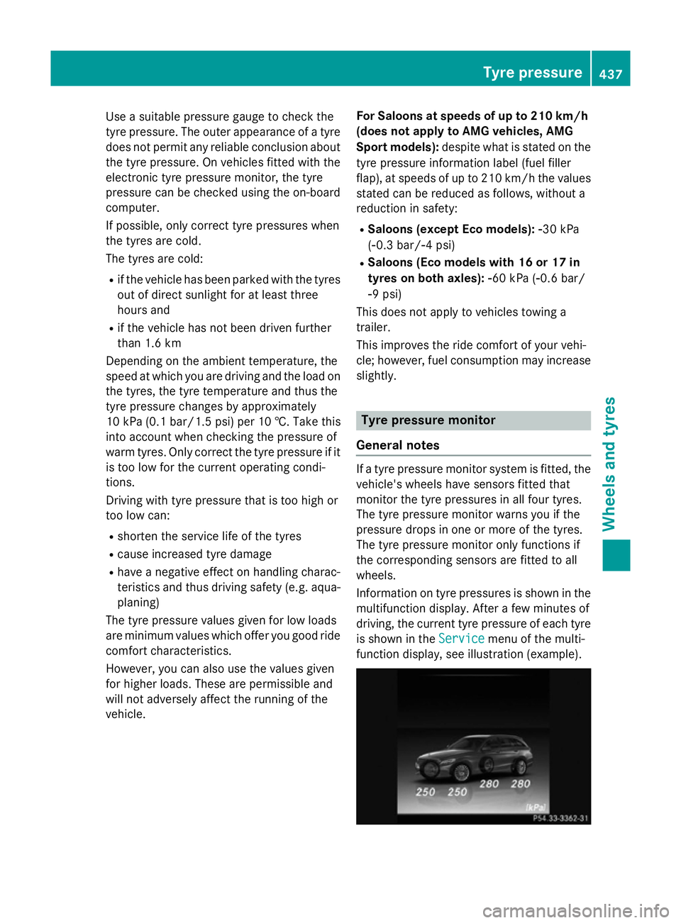
Information on tyre pressures is shown in the multifunction display. After a few minutes of
driving, the current tyre pressure of each tyre
is shown in the Service Servicemenu of the multi-
function display, see illustration (example). Tyre pressure
437Wheels and tyres Z
Page 441 of 489
For further information on displaying this
message, refer to the "Checking the tyre pres-
sure electronically" section (Y page 438).
Important safety notes It is the driver's responsibility to set the tyre
pressure to the recommended cold tyre pres-
sure suitable for the operating situation
(Y page 436). Note that the correct tyre pres-
sure for the current operating situation must
first be taught-in to the tyre pressure monitor. If there is a substantial loss of pressure, the
warning threshold for the warning message is aligned to the reference values taught-in.
Restart the tyre pressure monitor after
adjusting to the cold tyre pressure
(Y page 439). The current pressures are
saved as new reference values. This will
ensure that a warning message will only
appear if the tyre pressure drops significantly.
The tyre pressure monitor does not warn you
of an incorrectly set tyre pressure. Observe
the notes on the recommended tyre pressure
(Y page 436).
The tyre pressure monitor is not able to warn
you of a sudden loss of pressure, e.g. if the
tyre is penetrated by a foreign object. In the
event of a sudden loss of pressure, bring the
vehicle to a halt by braking carefully. Avoid
abrupt steering manoeuvres.
The tyre pressure monitor has a yellow warn-
ing lamp in the instrument cluster for indicat- ing a pressure loss or malfunction. Depending
on how the warning lamp flashes or lights up, a tyre pressure that is too low or a malfunc-
tion in the tyre pressure monitor is indicated:
R if the warning lamp is lit continuously, the
tyre pressure on one or more tyres is sig-
nificantly too low. The tyre pressure moni-
tor is not malfunctioning.
R if the warning lamp flashes for around a
minute and then remains lit constantly, the
tyre pressure monitor is malfunctioning.
In addition to the warning lamp, a message
appears in the multifunction display. Further
information can be found under (Y page 345).If the tyre pressure monitor is malfunctioning,
it may take more than ten minutes for the tyre
pressure warning lamp to inform you of the
malfunction by flashing for approximately one minute and then remaining lit. When the fault
has been rectified, the tyre pressure warning lamp goes out after you have driven for a few
minutes.
The tyre pressure values indicated by the on- board computer may differ from those meas-
ured at a filling station using a pressure
gauge. The tyre pressures shown by the on-
board computer refer to those measured at
sea level. At high altitudes, the tyre pressure
values indicated by a pressure gauge are
higher than those shown by the on-board
computer. In this case, do not reduce the tyre
pressures.
The operation of the tyre pressure monitor
can be affected by interference from radio
transmitting equipment (e.g. radio head-
phones, two-way radios) that may be being
operated in or near the vehicle.
Checking the tyre pressure electroni-
cally X
Make sure that the key is in position 2
(Y page 185) in the ignition lock.
X Use ò on the steering wheel to call up
the list of menus.
X Press the 9or: button on the steer-
ing wheel to select the Service Servicemenu.
X Press the abutton.
X Press the 9or: button to select
Tyre pressure
Tyre pressure .
X Press the abutton.
The current tyre pressure for each wheel
will be displayed in the multifunction dis-
play.
If the vehicle has been parked for over
20 minutes, the Tyre
Tyre pressures pressures will
willbe
be
displayed after a few minutes of
displayed after a few minutes of
driving
driving message appears.
After a teach-in period, the tyre pressure
monitor automatically detects new wheels or 438
Tyre pressureWheels and tyres
Page 446 of 489
X
Vehicles with KEYLESS-GO start-func-
tion or KEYLESS-GO: remove the Start/
Stop button from the ignition lock
(Y page 185).
X If included in the vehicle equipment,
remove the tyre-change tool kit from the
vehicle.
X Secure the vehicle to prevent it from rolling
away.
i Apart from some country-specific var-
iants, vehicles are not equipped with tyre-
changing tools. Some tools for changing a
wheel are specific to the vehicle. For more information on which tools are required to
perform a wheel change on your vehicle,
consult a qualified specialist workshop.
Necessary wheel-changing tools may
include, for example:
R jack
R wheel chock
R wheel wrench
R centring pin
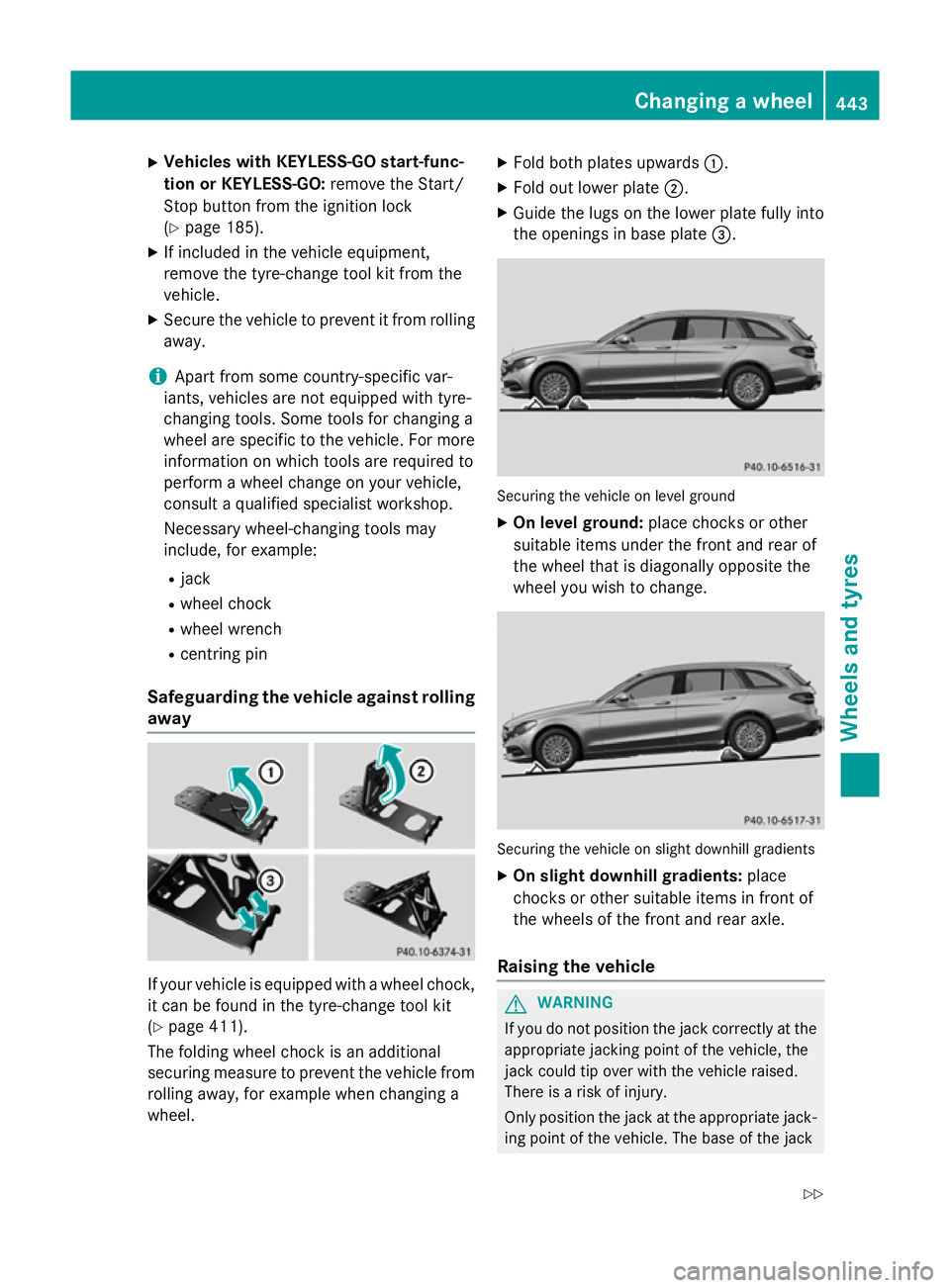
Safeguarding the vehicle against rolling
away If your vehicle is equipped with a wheel chock,
it can be found in the tyre-change tool kit
(Y page 411).
The folding wheel chock is an additional
securing measure to prevent the vehicle from
rolling away, for example when changing a
wheel. X
Fold both plates upwards :.
X Fold out lower plate ;.
X Guide the lugs on the lower plate fully into
the openings in base plate =. Securing the vehicle on level ground
X On level ground: place chocks or other
suitable items under the front and rear of
the wheel that is diagonally opposite the
wheel you wish to change. Securing the vehicle on slight downhill gradients
X On slight downhill gradients: place
chocks or other suitable items in front of
the wheels of the front and rear axle.
Raising the vehicle G
WARNING
If you do not position the jack correctly at the appropriate jacking point of the vehicle, the
jack could tip over with the vehicle raised.
There is a risk of injury.
Only position the jack at the appropriate jack-
ing point of the vehicle. The base of the jack Changing a wheel
443Wheels and tyres
Z
Page 447 of 489
must be positioned vertically, directly under
the jacking point of the vehicle.
Observe the following when raising the
vehicle: R to raise the vehicle, only use the vehicle-
specific jack that has been tested and
approved by Mercedes-Benz. If the jack is
used incorrectly, it could tip over while the vehicle is raised.
R the jack is designed only to raise and hold
the vehicle for a short time while a wheel
is being changed. It is not suitable for per-
forming maintenance work under the vehi- cle.
R avoid changing the wheel on uphill and
downhill slopes.
R before raising the vehicle, secure it from
rolling away by applying the parking brake
and positioning wheel chocks. Do not
release the parking brake while the vehicle
is raised.
R the jack must be placed on a firm, flat and
non-slip surface. On a loose surface, a
large, flat load-bearing underlay must be
used. On a slippery surface, a non-slip
underlay must be used, e.g. rubber mats.
R do not use wooden blocks or similar
objects as a jack underlay. Otherwise, the
jack will not be able to achieve its load-
bearing capacity due to the restricted
height.
R make sure that the distance between the
underside of the tyres and the ground does not exceed 3 cm.
R never place your hands or feet under the
raised vehicle.
R do not lie under the vehicle.
R do not start the engine when the vehicle is
raised.
R do not open or close a door or the tailgate
while the vehicle is raised.
R make sure that no persons are present in
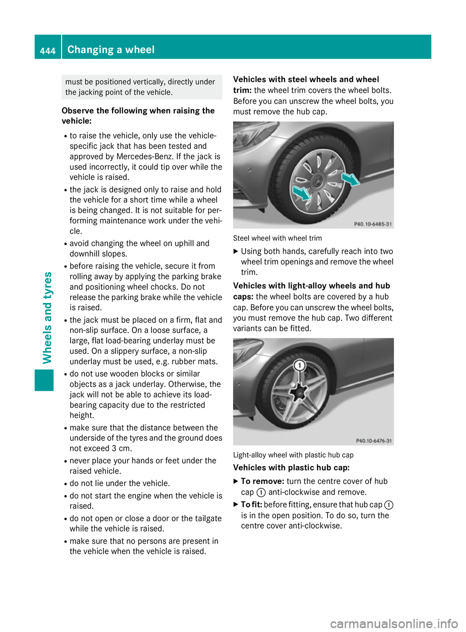
the vehicle when the vehicle is raised. Vehicles with steel wheels and wheel
trim:
the wheel trim covers the wheel bolts.
Before you can unscrew the wheel bolts, you must remove the hub cap. Steel wheel with wheel trim
X
Using both hands, carefully reach into two
wheel trim openings and remove the wheel trim.
Vehicles with light-alloy wheels and hub
caps: the wheel bolts are covered by a hub
cap. Before you can unscrew the wheel bolts, you must remove the hub cap. Two different
variants can be fitted. Light-alloy wheel with plastic hub cap
Vehicles with plastic hub cap:
X To remove: turn the centre cover of hub
cap :anti-clockwise and remove.
X To fit: before fitting, ensure that hub cap :
is in the open position. To do so, turn the
centre cover anti-clockwise. 444
Changing a wheelWheels and tyres
Page 448 of 489
X
Put hub cap :in position and turn the
centre cover clockwise until you feel and
hear hub cap :engage.
X Make sure that hub cap :is fitted
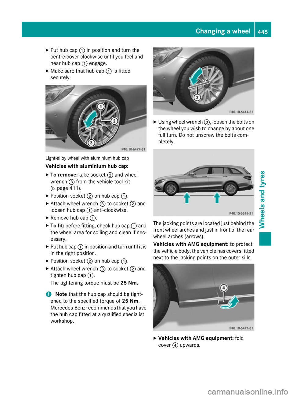
securely. Light-alloy wheel with aluminium hub cap
Vehicles with aluminium hub cap:
X To remove: take socket;and wheel
wrench =from the vehicle tool kit
(Y page 411).
X Position socket ;on hub cap :.
X Attach wheel wrench =to socket ;and
loosen hub cap :anti-clockwise.
X Remove hub cap :.
X To fit: before fitting, check hub cap :and
the wheel area for soiling and clean if nec-
essary.
X Put hub cap :in position and turn until it is
in the right position.
X Position socket ;on hub cap :.
X Attach wheel wrench =to socket ;and
tighten hub cap :.
The tightening torque must be 25 Nm.
i Note
that the hub cap should be tight-
ened to the specified torque of 25 Nm.
Mercedes-Benz recommends that you have the hub cap fitted at a qualified specialist
workshop. X
Using wheel wrench =, loosen the bolts on
the wheel you wish to change by about one full turn. Do not unscrew the bolts com-
pletely. The jacking points are located just behind the
front wheel arches and just in front of the rear wheel arches (arrows).
Vehicles with AMG equipment: to protect
the vehicle body, the vehicle has covers fitted next to the jacking points on the outer sills. X
Vehicles with AMG equipment: fold
cover ?upwards. Changing a wheel
445Wheels and tyres Z
Page 467 of 489
Inflating the collapsible emergency
spare wheel
! Inflate the collapsible emergency spare
wheel using the tyre inflation compressor
before lowering the vehicle. The wheel rim
could otherwise be damaged.
! Do not operate the tyre inflation com-
pressor for longer than eight minutes at a
time without a break. It may otherwise
overheat.
The tyre inflation compressor can be oper-
ated again once it has cooled down. X
Mount the collapsible emergency spare
wheel as described (Y page 441).
The collapsible emergency spare wheel
must be mounted before it is inflated.
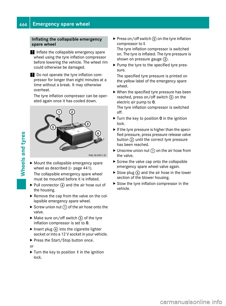
X Pull connector ?and the air hose out of
the housing.
X Remove the cap from the valve on the col-
lapsible emergency spare wheel.
X Screw union nut :of the air hose onto the
valve.
X Make sure on/off switch Aof the tyre
inflation compressor is set to 0.
X Insert plug ?into the cigarette lighter
socket or into a 12 V socket in your vehicle.
X Press the Start/Stop button once.
or X Turn the key to position 1in the ignition
lock. X
Press on/off switch Aon the tyre inflation
compressor to I.
The tyre inflation compressor is switched
on. The tyre is inflated. The tyre pressure is shown on pressure gauge =.
X Pump the tyre to the specified tyre pres-
sure.
The specified tyre pressure is printed on
the yellow label of the emergency spare
wheel.
X When the specified tyre pressure has been
reached, press on/off switch Aon the
electric air pump to 0.
The tyre inflation compressor is switched
off.
X Turn the key to position 0in the ignition
lock.
X If the tyre pressure is higher than the speci-
fied pressure, press pressure release valve
button ;until the correct tyre pressure
has been reached.
X Unscrew union nut :on the air hose from
the valve.
X Screw the valve cap onto the collapsible
emergency spare wheel valve again.
X Stow plug ?and the air hose in the lower
section of the blower housing.
X Stow the tyre inflation compressor in the
vehicle. 464
Emergency spare wheelWheels and ty
res
Page 468 of 489
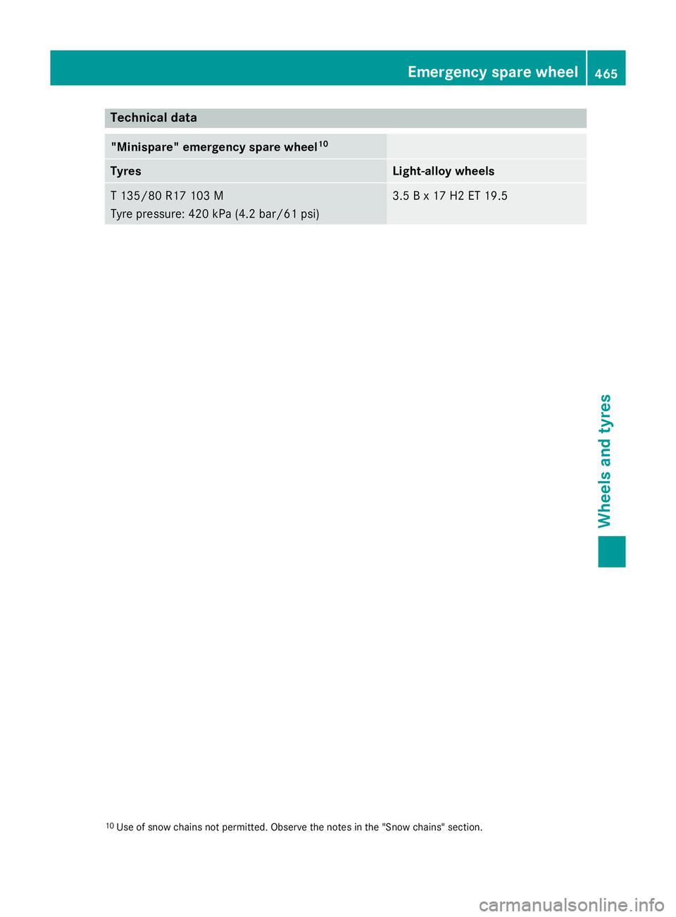
Technical data
"Minispare" emergency spare wheel
10Tyres Light-alloy wheels
T 135/8
0 R17 103 M
Tyre pressure : 420 kPa (4.2 ba r/61 psi) 3.5 B x 17 H2 ET 19.5
10
Use of snow chains not permitted. Observe the notes in the "Snow chains" section. Emergency spare wheel
465Wheels and tyres Z