2014 Lancia Voyager ad blue
[x] Cancel search: ad bluePage 116 of 364

Bluetooth® Streaming (BT) Mode
To switch to Bluetooth® Streaming
(BT) mode, say “Bluetooth Stream-
ing.” In this mode, you may say the
following commands:
“Next Track” (to play the nexttrack)
“Previous Track” (to play the pre- vious track)
“List” (to list an Artist, Playlist, Album, Track, etc.)
Memo Mode
To switch to the voice recorder mode,
say “Memo.” In this mode, you may
say the following commands:
“New Memo” (to record a new memo) — During the recording,
you may press the Voice Command
button to stop recording. You
proceed by saying one of the follow-
ing commands:
– “Save” (to save the memo)
– “Continue” (to continue recording)
–
“Delete” (to delete the recording)
“Play Memos” (to play previously recorded memos) — During the
playback you may press the Voice
Command
button to stop
playing memos. You proceed by
saying one of the following com-
mands:
– “Repeat” (to repeat a memo)
– “Next” (to play the next memo)
– “Previous” (to play the previous memo)
– “Delete” (to delete a memo)
– “Delete All” (to delete all memos)
System Setup
To switch to system setup, you may
say one of the following:
“Change to system setup”
“Main menu system setup”
“Switch to system setup”
“Change to setup”
“Main menu setup” or
“Switch to setup” In this mode, you may say the follow-
ing commands:
“Language English”
“Language French”
“Language Spanish”
“Language Dutch”
“Language Deutsch”
“Language Italian”
“Tutorial”
“Voice Training”
NOTE: Keep in mind that you
have to press the Voice Command
button first and wait for the
beep before speaking the “Barge
In” commands.
VOICE TRAINING
For users experiencing difficulty with
the system recognizing their voice
commands or numbers the
Uconnect® Voice “Voice Training”
feature may be used.
1. Press the Voice Command
button, say “System Setup” and
110
Page 172 of 364

KEYLESS ENTER-N-GO™ DISPLAY (forversions/markets, where provided) .........186
COMPASS / TEMPERATURE DISPLAY (for versions/markets, where provided) .........186
CUSTOMER-PROGRAMMABLE FEATURES (SYSTEM SETUP) ..................... .189
SOUND SYSTEMS ....................... .193
NAVIGATION SYSTEM (for versions/markets, where provided) .............................. .193
iPod®/USB/MP3 CONTROL (for versions/markets, where equipped) ........................ .193
CONNECTING THE iPod® OR EXTERNAL USB DEVICE ............................. .194
USING THIS FEATURE ...................194
CONTROLLING THE iPod® OR EXTERNAL USB DEVICE USING RADIO BUTTONS ..........194
PLAY MODE .......................... .194
LIST OR BROWSE MODE ................195
BLUETOOTH STREAMING AUDIO (BTSA) . . . .197
Uconnect® MULTIMEDIA VIDEO ENTERTAINMENT SYSTEM (VES™) (for versions/markets, where
provided) .............................. .197
GETTING STARTED .................... .197
Blu-ray® PLAYER ..................... .197
PLAY VIDEO GAMES ................... .198
LISTEN TO AN AUDIO SOURCE ON CHANNEL 2
WHILE A VIDEO IS PLAYING ON CHANNEL 1 . .198
DUAL VIDEO SCREEN ...................198
166
Page 203 of 364

WARNING!
Do not plug in or remove the iPod®
or external USB device while driv-
ing. Failure to follow this warning
could result in an accident.
BLUETOOTH STREAMING
AUDIO (BTSA)
Music can be streamed from your cel-
lular phone to the Uconnect® phone
system.
Uconnect® MULTIMEDIA
VIDEO
ENTERTAINMENT
SYSTEM (VES™) (for
versions/markets, where
provided)
GETTING STARTED
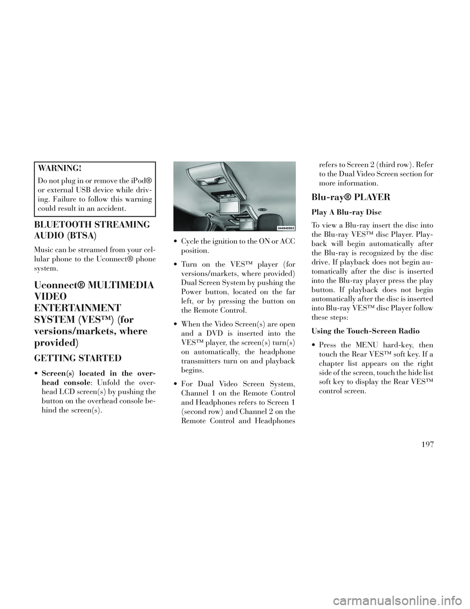
Screen(s) located in the over-
head console: Unfold the over-
head LCD screen(s) by pushing the
button on the overhead console be-
hind the screen(s). Cycle the ignition to the ON or ACC
position.
Turn on the VES™ player (for versions/markets, where provided)
Dual Screen System by pushing the
Power button, located on the far
left, or by pressing the button on
the Remote Control.
When the Video Screen(s) are open and a DVD is inserted into the
VES™ player, the screen(s) turn(s)
on automatically, the headphone
transmitters turn on and playback
begins.
For Dual Video Screen System, Channel 1 on the Remote Control
and Headphones refers to Screen 1
(second row) and Channel 2 on the
Remote Control and Headphones refers to Screen 2 (third row). Refer
to the Dual Video Screen section for
more information.
Blu-ray® PLAYER
Play A Blu-ray Disc
To view a Blu-ray insert the disc into
the Blu-ray VES™ disc Player. Play-
back will begin automatically after
the Blu-ray is recognized by the disc
drive. If playback does not begin au-
tomatically after the disc is inserted
into the Blu-ray player press the play
button. If playback does not begin
automatically after the disc is inserted
into Blu-ray VES™ disc Player follow
these steps:
Using the Touch-Screen Radio
Press the MENU hard-key, then
touch the Rear VES™ soft key. If a
chapter list appears on the right
side of the screen, touch the hide list
soft key to display the Rear VES™
control screen.
197
Page 287 of 364

The electrical connections are all
complete to the vehicle but you must
mate the harness to a trailer connec-
tor.
Seven - Pin Connector Details
Pin Function Wire
Color
1 Left Turn Signal Yellow
2 Rear Fog Light Blue
3 Ground/Common Return White
4 Right Turn Signal Green
5 Right Rear Posi- tion, Side MarkerLights, and Rear
Registration Plate Illumination De- vice
1
Brown
Seven - Pin Connector Details
Pin Function Wire
Color
6 Stop Lights Red
7 Left Rear Position, Side Marker
Lights, and Rear
Registration Plate Illumination De- vice
1
Black
1The rear position registration
plate illumination device shall be
connected such that no light of the device has a common connection with both pins 5 and 7.
Thirteen - Pin Connector Details
Pin Function Wire Color
1 Left Turn Signal Yellow
2 Rear Fog Light Blue
3 Ground/Common Return for Con-
tacts (Pins) 1 and 2and4to8
2
White
4 Right Turn Signal Green
5 Right Rear Posi- tion, Side MarkerLights, and Rear
Registration Plate Illumination De- vice.
b
Brown
6 Stop Lights Red
7 Left Rear Position, Side Marker
Lights, and Rear
Registration Plate Illumination De- vice
1
Black
8 Reverse Lights Red/ Black
Seven - Pin Connector
Thirteen - Pin Connector
281
Page 288 of 364

Thirteen - Pin ConnectorDetails
Pin Function Wire Color
9 Permanent Power Supply (+12V) Brown/
White
10 Power Supply Controlled by Ig-nition Switch (+12V) Red
11
aReturn for Contact (Pin) 102White
12 Reserve for Future Allocation ³ Red/
Blue
13 Return for Contact (Pin) 9
2White
1The rear position registration
plate illumination device shall be
connected such that no light of the device has a common connection with both pins 5 and 7.
2The three return circuits shall notbe connected electrically in the trailer.
³The allocation pin 12 has been
changed from “Coding for coupled Trailer” to “Reserve for Future Allocation.”
TOWING TIPS
Before setting out on a trip, practice
turning, stopping and backing the
trailer in an area away from heavy
traffic.
Automatic Transmission
The DRIVE gear can be selected when
towing. However, if frequent shifting
occurs while in DRIVE, use the Elec-
tronic Range Select (ERS) shift con-
trol to select a lower gear range.
NOTE: Using a lower gear range
while operating the vehicle under
heavy loading conditions will im-
prove performance and extend
transmission life by reducing ex-
cessive shifting and heat build up.
This action will also provide better
engine braking.
If you REGULARLY tow a trailer for
more than 45 minutes of continuous
operation, then change the transmis-
sion fluid and filter as specified for
"police, taxi, fleet, or frequent trailer
towing." Refer to the “Maintenance
Schedule” for the proper maintenance
intervals. Electronic Range Select (ERS)
When using the ERS shift control,
select the highest gear range that
allows for adequate performance
and avoids frequent downshifts.
For example, choose “4” if the de-
sired speed can be maintained.
Choose “3” or “2” if needed to
maintain the desired speed.
To prevent excess heat generation, avoid continuous driving at high
RPM. Reduce vehicle speed as nec-
essary to avoid extended driving at
high RPM. Return to a higher gear
or vehicle speed when grade and
road conditions allow.
Electronic Speed Control (for
versions/markets, where
provided)
Do not use in hilly terrain or with heavy loads.
When using the speed control, if you experience speed drops greater
than 16 km/h, disengage until you
can get back to cruising speed.
282
Page 332 of 364

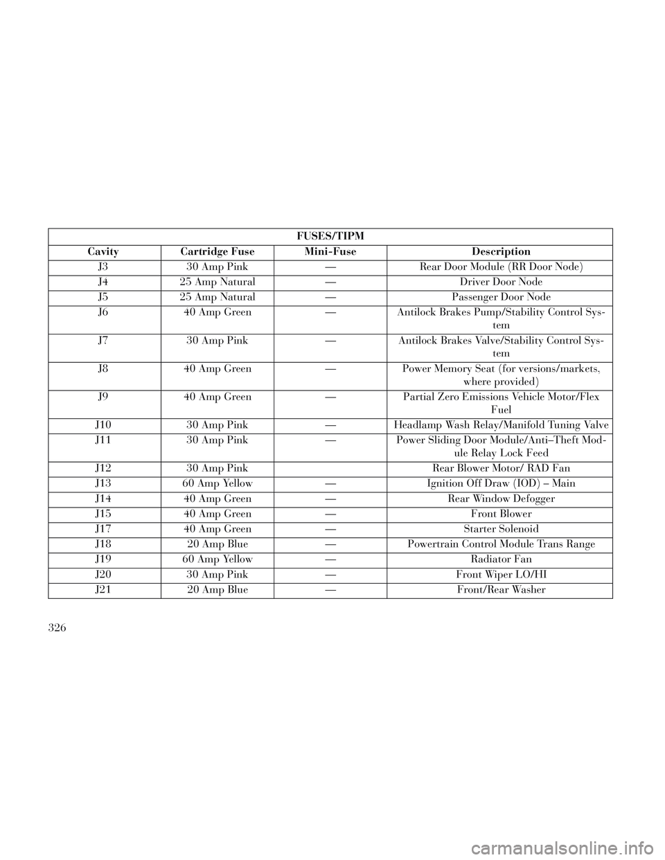
FUSES/TIPM
Cavity Cartridge Fuse Mini-Fuse Description J3 30 Amp Pink — Rear Door Module (RR Door Node)
J4 25 Amp Natural — Driver Door Node
J5 25 Amp Natural — Passenger Door Node
J6 40 Amp Green — Antilock Brakes Pump/Stability Control Sys- tem
J7 30 Amp Pink — Antilock Brakes Valve/Stability Control Sys- tem
J8 40 Amp Green — Power Memory Seat (for versions/markets, where provided)
J9 40 Amp Green — Partial Zero Emissions Vehicle Motor/Flex Fuel
J10 30 Amp Pink —Headlamp Wash Relay/Manifold Tuning Valve
J11 30 Amp Pink —Power Sliding Door Module/Anti–Theft Mod-
ule Relay Lock Feed
J12 30 Amp Pink Rear Blower Motor/ RAD Fan
J13 60 Amp Yellow —Ignition Off Draw (IOD) – Main
J14 40 Amp Green —Rear Window Defogger
J15 40 Amp Green — Front Blower
J17 40 Amp Green —Starter Solenoid
J18 20 Amp Blue —Powertrain Control Module Trans Range
J19 60 Amp Yellow — Radiator Fan
J20 30 Amp Pink —Front Wiper LO/HI
J21 20 Amp Blue —Front/Rear Washer
326
Page 333 of 364

FUSES/TIPM
Cavity Cartridge Fuse Mini-Fuse Description J22 25 Amp Natural — Sunroof ModuleM1 — 15 Amp Blue Rear Center Brake Lamp/Brake Switch
M2 — 20 Amp Yellow Trailer Lighting/Fog Lamps
M3 — 20 Amp Yellow Front/Rear Axle Locker/Vacuum Pump Motor
M4 — 10 Amp Red Trailer Tow
M5 — 25 Amp Natural Inverter
M6 — 20 Amp Yellow Power Outlet #1 (ACC), Rain Sensor
M7 — 20 Amp Yellow Power Outlet #2 (BATT/ACC SELECT)
M8 — 20 Amp Yellow Front Heated Seat (for versions/markets, where provided)
M9 — 20 Amp Yellow Rear Heated Seat (for versions/markets, where provided)
M10 —15 Amp Blue Ignition Off Draw — Video System, DVD,
Hands-Free Module, Vanity Lamp, StreamingVideo Module
M11 —10 Amp Red Ignition Off Draw – Climate Control System
M12 —30 Amp Green Amplifier (AMP)/Radio
M13 —20 Amp Yellow Ignition Off Draw— Instrument Cluster, SI-
REN, Clock Module, Multi-Function ControlSwitch/ITM
M14 —20 Amp Yellow Spare Fuse
327
Page 334 of 364

FUSES/TIPM
Cavity Cartridge Fuse Mini-Fuse Description M15 — 20 Amp Yellow Rear View Mirror, Instrument Cluster, Multi- Function Control Switch, Tire Pressure Moni-tor, Glow Plug Module – Export Diesel Only, Assy-Shifter (Hall Effect), Acoustic Noise Cancellation
M16 —10 Amp Red Airbag Module/Occupant Classification Mod-
ule
M17 —15 Amp Blue Left Tail/License/Park Lamp, Running
Lamps
M18 —15 Amp Blue Right Tail/Park/Run Lamp
M19 —25 Amp Natural Automatic Shutdown #1 and #2
M20 —15 Amp Blue Instrument Cluster Interior Light, Switch
Bank, Steering Column Module, Switch Steer-ing Wheel
M21 —20 Amp Yellow Automatic Shutdown #3
M22 —10 Amp Red Right Horn (HI/LOW)
M23 —10 Amp Red Left Horn (HI/LOW)
M24 —25 Amp Natural Rear Wiper
M25 —20 Amp Yellow Fuel Pump, Diesel Lift Pump – Export Only
M26 —10 Amp Red Power Mirror Switch, Driver Window Switch
M27 —10 Amp Red Ignition Switch, Wireless Control Module,
Keyless Entry Module, Steering Column Lock
M28 —10 Amp Red Powertrain Control Module, Transmission
Feed, Transmission Control Module
328