Page 1441 of 1534
633
What to do in an emergency
When towing your vehicle in an emer- gency without wheel dollies :
1. Set the ignition switch in the ACC posi-tion.
2. Place the transaxle shift lever in N (Neutral).
3. Release the parking brake.
Removable towing hook (if equipped)
1. Open the tailgate, and remove the tow-ing hook from the tool case.
2. Remove the hole cover pressing the lower part of the cover on the front or
rear bumper. 3. Install the towing hook by turning it
clockwise into the hole until it is fullysecured.
4. Remove the towing hook and install the cover after use.
CAUTION
Failure to place the transaxle shift
lever in N (Neutral) may cause inter-
nal damage to the transaxle.OEL063013
OLM069016L
■ Front
■Rear (if equipped)
EL(FL) UK 6.QXP 8/5/2013 6:55 PM Page 33
Page 1460 of 1534
Maintenance
16
7
ENGINE COOLANT
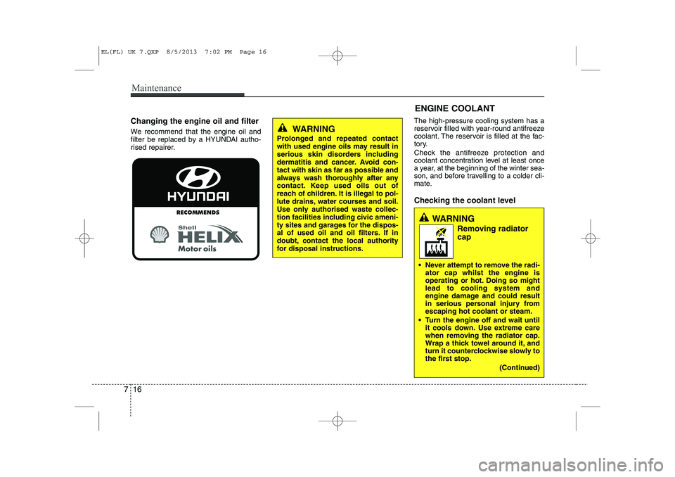
Changing the engine oil and filter
We recommend that the engine oil and
filter be replaced by a HYUNDAI autho-
rised repairer. The high-pressure cooling system has a
reservoir filled with year-round antifreeze
coolant. The reservoir is filled at the fac-
tory.
Check the antifreeze protection and
coolant concentration level at least once
a year, at the beginning of the winter sea-
son, and before travelling to a colder cli-
mate.
Checking the coolant level
WARNING
Removing radiator cap
Never attempt to remove the radi- ator cap whilst the engine is
operating or hot. Doing so mightlead to cooling system and
engine damage and could result
in serious personal injury fromescaping hot coolant or steam.
Turn the engine off and wait until it cools down. Use extreme care
when removing the radiator cap.
Wrap a thick towel around it, and
turn it counterclockwise slowly to
the first stop.
(Continued)
WARNING
Prolonged and repeated contact
with used engine oils may result in
serious skin disorders including
dermatitis and cancer. Avoid con-
tact with skin as far as possible and
always wash thoroughly after any
contact. Keep used oils out of
reach of children. It is illegal to pol-
lute drains, water courses and soil.
Use only authorised waste collec-
tion facilities including civic ameni-
ty sites and garages for the dispos-
al of used oil and oil filters. If in
doubt, contact the local authority
for disposal instructions.
EL(FL) UK 7.QXP 8/5/2013 7:02 PM Page 16
Page 1461 of 1534
717
Maintenance
Check the condition and connections of all cooling system hoses and heater
hoses. Replace any swollen or deterio-
rated hoses.
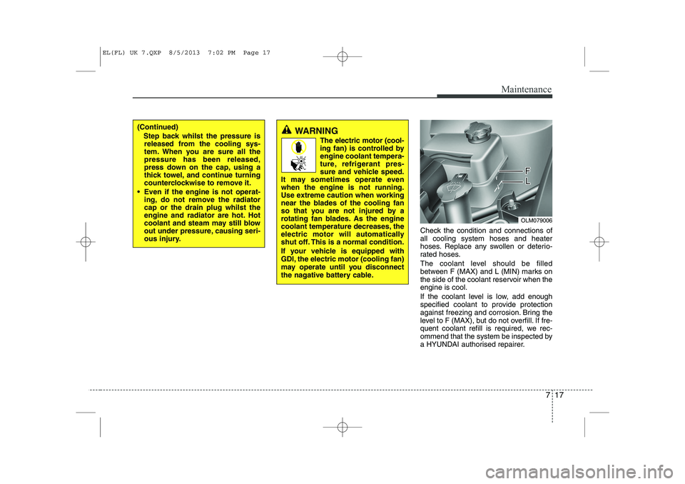
The coolant level should be filled
between F (MAX) and L (MIN) marks on
the side of the coolant reservoir when theengine is cool.
If the coolant level is low, add enough
specified coolant to provide protection
against freezing and corrosion. Bring the
level to F (MAX), but do not overfill. If fre-
quent coolant refill is required, we rec-
ommend that the system be inspected by
a HYUNDAI authorised repairer.
OLM079006
(Continued)Step back whilst the pressure isreleased from the cooling sys-
tem. When you are sure all thepressure has been released,
press down on the cap, using a
thick towel, and continue turning
counterclockwise to remove it.
Even if the engine is not operat- ing, do not remove the radiatorcap or the drain plug whilst the
engine and radiator are hot. Hot
coolant and steam may still blow
out under pressure, causing seri-
ous injury.WARNING
The electric motor (cool-
ing fan) is controlled byengine coolant tempera-
ture, refrigerant pres-
sure and vehicle speed.
It may sometimes operate evenwhen the engine is not running.
Use extreme caution when working
near the blades of the cooling fan
so that you are not injured by a
rotating fan blades. As the engine
coolant temperature decreases, the
electric motor will automatically
shut off. This is a normal condition.
If your vehicle is equipped with
GDI, the electric motor (cooling fan)
may operate until you disconnect
the nagative battery cable.
EL(FL) UK 7.QXP 8/5/2013 7:02 PM Page 17
Page 1476 of 1534
Maintenance
32
7
Battery recharging
Your vehicle has a maintenance-free,
calcium-based battery.
If the battery becomes discharged in a
short time (because, for example, the
headlights or interior lights were left on
whilst the vehicle was not in use),
recharge it by slow charging (trickle)
for 10 hours.
If the battery gradually discharges because of high electric load whilst the
vehicle is being used, recharge it at 20-
30A for two hours. Reset items
Items should be reset after the battery
has been discharged or the battery hasbeen disconnected.
Auto up/down window (See section 4)
Sunroof (See section 4)
Trip computer (See section 4)
Climate control system
(See section 4)
Clock (See section 4)
Audio (See section 4)(Continued)
Before performing maintenance or recharging the battery, turn off all accessories and stop the
engine.
The negative battery cable must be removed first and installed
last when the battery is discon-nected.WARNING - Recharging
battery
When recharging the battery,
observe the following precautions:
The battery must be removed from the vehicle and placed in an area with good ventilation.
Do not allow cigarettes, sparks, or flame near the battery.
Watch the battery during charg- ing, and stop or reduce the charg-
ing rate if the battery cells begin
gassing (boiling) violently or if
the temperature of the electrolyte
of any cell exceeds 49°C (120°F).
Wear eye protection when check- ing the battery during charging.
Disconnect the battery charger in the following order.
1. Turn off the battery charger main switch.
2. Unhook the negative clamp from the negative battery ter- minal.
3. Unhook the positive clamp from the positive battery termi-nal.
(Continued)
EL(FL) UK 7.QXP 8/5/2013 7:03 PM Page 32
Page 1495 of 1534
751
Maintenance
No.Fuse ratingSymbolFuse NameCircuit Protected
1010AAIR BAGSRS Control Module, Passenger Air Bag Lamp
1110AMODULE 1
IPS Control Module (ON/START Input), 4WD ECM, ICM Relay Box (DBC Relay),
DBC Switch, Multifunction Switch (Light), Steering Angle Sensor, Stop Lamp Switch,
EPS Control Module, Tyre Pressure Monitoring Module, ESP Off Switch, E/R Fuse &
Relay Box (RLY. 8 - ESS), DC/DC Converter, Smart Parking Assist Control Module
1215AHANDLE HTDClock Spring (Steering Wheel Heater)
1310AFOG LP RRICM Relay Box (Rear Fog Lamp Relay)
1425AWIPER FRTE/R Fuse & Relay Box (RLY. 12 - Front Wiper LO, RLY. 13 - Rain Wiper)
Front Wiper Motor, Multifunction Switch (Wiper)
1515AS/HEATER FRTConsole Switch
1620APOWER OUTLET 1Cigarette Lighter & Front Power Outlet
1710ABACK-UP LPBack-Up Lamp Relay
Rear Parking Assist Sensor LH/RH, Rear Parking Assist Sensor Centre LH/RH
1815ADR LOCKDoor Lock/Unlock Relay, Tail Gate Relay, ICM Relay Box (Dead Lock Relay)
197.5AMODULE 2BCM, Smart Key Control Module, PDM
2015AWIPER RRICM Relay Box (Rear Wiper Relay), Rear Wiper Motor, Multifunction Switch (Wiper)
2115ASUNROOFSunroof Motor
EL(FL) UK 7.QXP 8/5/2013 7:04 PM Page 51
Page 1501 of 1534
757
Maintenance
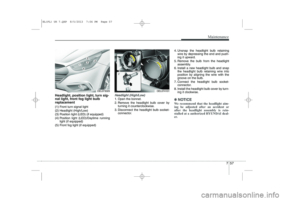
Headlight, position light, turn sig-
nal light, front fog light bulbreplacement
(1) Front turn signal light
(2) Headlight (High/Low)
(3) Position light (LED) (if equipped)
(4) Position light (LED)/Daytime runninglight (if equipped)
(5) Front fog light (if equipped)Headlight (High/Low)
1. Open the bonnet.
2. Remove the headlight bulb cover by turning it counterclockwise.
3. Disconnect the headlight bulb socket- connector. 4. Unsnap the headlight bulb retaining
wire by depressing the end and push-
ing it upward.
5. Remove the bulb from the headlight assembly.
6. Install a new headlight bulb and snap the headlight bulb retaining wire into
position by aligning the wire with the
groove on the bulb.
7. Connect the headlight bulb socket- connector.
8. Install the headlight bulb cover by turn- ing it clockwise.✽✽ NOTICE
We recommend that the headlight aim-
ing be adjusted after an accident or
after the headlight assembly is rein-stalled at a authorized HYUNDAI deal-
er.
OEL073029OEL074101
EL(FL) UK 7.QXP 8/5/2013 7:04 PM Page 57
Page 1503 of 1534
759
Maintenance
Turn signal light/Position light
Turn signal light
1. Turn off the engine and open the bon-net.
2. Remove the socket from the assembly by turning the socket counterclockwise
until the tabs on the socket align with
the slots on the assembly.
3. Remove the bulb from the socket by pressing it in and rotating it counter-
clockwise until the tabs on the bulb
align with the slots in the socket. Pull
the bulb out of the socket.
4. Insert a new bulb by inserting it into the socket and rotating it until it locks
into place.
5. Install the socket in the assembly by aligning the tabs on the socket with the
slots in the assembly. Push the socket
into the assembly and turn the socket
clockwise. Position light
If the light bulb does not operate, we rec-
ommend that the system be checked by
a HYUNDAI authorised repairer.(Continued)
If a bulb becomes damaged or
cracked, replace it immediately
and carefully dispose of it.
Wear eye protection when chang- ing a bulb. Allow the bulb to cool
down before handling it.
EL(FL) UK 7.QXP 8/5/2013 7:04 PM Page 59
Page 1504 of 1534
Maintenance
60
7
Front fog light bulbs (if equipped)
1. Remove the front bumper under cover.
2. Reach your hand into the back of the
front bumper.
3. Disconnect the power connector from the socket.
4. Remove the bulb-socket from the housing by turning the socket counter
clockwise until the tabs on the socketalign with the slots on the housing.
5. Install the new bulb-socket into the housing by aligning the tabs on the
socket with the slots in the housing.
Push the socket into the housing and
turn the socket clockwise.
6. Connect the power connector to the socket.
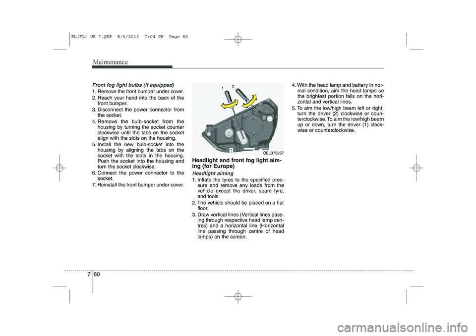
7. Reinstall the front bumper under cover. Headlight and front fog light aim-
ing (for Europe)
Headlight aiming
1. Inflate the tyres to the specified pres-
sure and remove any loads from the
vehicle except the driver, spare tyre,
and tools.
2. The vehicle should be placed on a flat floor.
3. Draw vertical lines (Vertical lines pass- ing through respective head lamp cen-
tres) and a horizontal line (Horizontalline passing through centre of headlamps) on the screen. 4. With the head lamp and battery in nor-
mal condition, aim the head lamps so
the brightest portion falls on the hori-
zontal and vertical lines.
5. To aim the low/high beam left or right, turn the driver (2) clockwise or coun-
terclockwise. To aim the low/high beam
up or down, turn the driver (1) clock-
wise or counterclockwise.
OEL073257
EL(FL) UK 7.QXP 8/5/2013 7:04 PM Page 60