2014 FORD F250 engine
[x] Cancel search: enginePage 205 of 460

To install the floor mats, position the floor
mat eyelet over the retention post and
press down to lock in position.
Remove in reverse order.
SNOWPLOWING
Ford recommends that the Super Duty
F-Series used for snow removal include
the snowplow package option.
Installing the Snowplow
Weight limits and guidelines for selecting
and installing the snowplow are in the Ford
Truck Body Builders Layout Book,
snowplow section, found at
www.fleet.ford.com/truckbbas. A typical
installation affects the following:
•
Certification to government safety laws
such as occupant protection and airbag
deployment, braking, and lighting. Look
for an Alterer ’s Label on the vehicle
from the snowplow installer certifying
that the installation meets all
applicable Federal Motor Vehicle
Safety Standards (FMVSS).
• The Total Accessory Reserve Capacity
(TARC) is on the lower right side of the
vehicle ’s Safety Compliance
Certification Label. This applies to
Ford-completed vehicles of 10,000
pounds (4,536 kilograms) GVWR or
less. This is the weight of
permanently-attached auxiliary
equipment, such as snowplow
frame-mounting hardware, that can
be added to the vehicle and satisfy
Ford compliance certification to
FMVSS. Exceeding this weight may
require the auxiliary equipment installer
additional safety certification
responsibility. The Front Accessory
Reserve Capacity (FARC) is for
customer convenience. •
Rear ballast weight behind the rear
axle may be required to prevent
exceeding the FGAWR, and provide
front-to-rear weight balance for proper
braking and steering.
• Front wheel toe may require
re-adjustment to prevent premature
uneven tire wear. Specifications are in
the Ford Workshop Manual.
• Headlight aim may require
re-adjustment.
• The tire air pressures recommended
for general driving are on the vehicle ’s
Safety Certification Label. The
maximum cold inflation pressure for
the tire and associated load rating is
on the tire sidewall. Tire air pressure
may require re-adjustment within these
pressure limits to accommodate the
additional weight of the snowplow
installation.
• Federal and some local regulations
require additional exterior lamps for
snowplow-equipped vehicles. Consult
your authorized dealer for additional
information.
Operating the Vehicle with the
Snowplow Attached
Note: Do not use your vehicle for snow
removal until you have driven at least 500
miles (800 kilometers).
Ford recommends vehicle speed does not
exceed 44.7 mph (72 km/h) when
snowplowing.
The attached snowplow blade restricts
airflow to the radiator, and may cause the
engine to run at a higher temperature:
Attention to engine temperature is
especially important when outside
temperatures are above freezing. Angle
the blade to maximize airflow to the
radiator and monitor engine temperature
to determine whether a left or right angle
provides the best performance.
202
Super Duty (TFA) Driving Hints
Page 206 of 460

Follow the severe duty schedule in your
Scheduled Maintenance information for
engine oil and transmission fluid change
intervals.
Snowplowing with your Airbag
Equipped Vehicle
WARNINGS
Do not attempt to service, repair, or
modify the airbag supplemental
restraint system (SRS) or its fuses.
See your Ford or Lincoln Mercury dealer. Additional equipment such as
snowplow equipment may affect the
performance of the airbag sensors
increasing the risk of injury. Please refer to
the Body Builders Layout Book for
instructions about the appropriate
installation of additional equipment. All occupants of the vehicle,
including the driver, should always
properly wear their safety belts, even
when provided with an airbag
supplemental restraint system (SRS). Your vehicle is equipped with a driver and
passenger airbag supplemental restraint
system. The supplemental restraint system
will activate in certain frontal and offset
frontal collisions when the vehicle sustains
sufficient frontal deceleration.
Careless or high speed driving while
plowing snow that results in sufficient
vehicle decelerations can deploy the
airbag. Such driving also increases the risk
of accidents
Never remove or defeat the tripping
mechanisms designed into the snow
removal equipment by its manufacturer.
Doing so may cause damage to the vehicle
and the snow removal equipment as well
as possible airbag deployment. Engine temperature while plowing
When driving with a plow, your engine may
run at a higher temperature than normal
because the attached snowplow blade will
restrict airflow to the radiator.
•
If you are driving more than 14.91 mi
(24 km) at temperatures above
freezing, angle the plow blade either
full left or full right to provide
maximum airflow to the radiator.
• If you are driving less than
14.91 mi
(24 km) at speeds up to 44.7 mph
(72 km/h) in cold weather, you will not
need to worry about blade position to
provide maximum airflow.
Transmission operation while
plowing WARNING
Do not spin the wheels at over
34.2 mph (55 km/h)
. The tires may
fail and injure a passenger or
bystander. •
Shift transfer case to
4L (4WD Low)
when plowing in small areas at speeds
below 5 mph (8 km/h).
• Shift transfer case to
4H (4WD High)
when plowing larger areas or light snow
at higher speeds. Do not exceed 15 mph
(24 km/h).
• Do not shift the transmission from a
forward gear to
R (Reverse) until the
engine is at idle and the wheels have
stopped.
203
Super Duty (TFA) Driving Hints
Page 208 of 460

HAZARD WARNING FLASHERS
Note:
The hazard warning flashers will
operate when the ignition is in any position
or if the key is not in the ignition. If used
when the engine is not running, the battery
will lose charge. As a result, there may be
insufficient power to restart your engine. In some models, the hazard
flasher control is located on the
instrument panel.
In other models, this feature is located on
the steering column, just behind the
steering wheel. Use your hazard warning flashers when
your vehicle is creating a safety hazard for
other motorists.
•
Press the flasher control and all front
and rear direction indicators flash.
• Press the flasher control again to turn
them off.
FUEL SHUTOFF WARNING
Failure to inspect and, if necessary,
repair fuel leaks after a collision may
increase the risk of fire and serious
injury. Ford Motor Company recommends
that the fuel system be inspected by an
authorized dealer after any collision. In the event of a moderate to severe
collision, this vehicle is equipped with a
fuel pump shut-off feature that stops the
flow of fuel to the engine. Not every impact
will cause a shut-off.
Should your vehicle shut off after a
collision, you may restart your vehicle by
doing the following:
1. Turn the ignition off.
2. Turn the ignition to crank.
3. Turn the ignition off.
4.
Turn the ignition on again to re-enable
the fuel pump.
JUMP-STARTING THE VEHICLE WARNINGS
The gases around the battery can
explode if exposed to flames, sparks,
or lit cigarettes. An explosion could
result in injury or vehicle damage. Batteries contain sulfuric acid which
can burn skin, eyes and clothing, if
contacted.
Use only an adequate-sized cable
with insulated clamps.
Preparing Your Vehicle
Note:
Do not attempt to push-start your
automatic transmission vehicle. Automatic
transmissions do not have push-start
capability. Attempting to push-start a
vehicle with an automatic transmission may
cause transmission damage.
Note: Use only a 12-volt supply to start your
vehicle.
Note: Do not disconnect the battery of the
disabled vehicle as this could damage the
vehicle's electrical system.
205
Super Duty (TFA) Roadside EmergenciesE142663 E161463
Page 209 of 460

Park the booster vehicle close to the hood
of the disabled vehicle, making sure the
two vehicles do not touch. Turn all
accessories off.
Connecting the Jumper Cables
WARNING
Do not attach the cables to fuel lines,
engine rocker covers, the intake
manifold or electrical components
as grounding points. Stay clear of moving
parts. To avoid reverse polarity
connections, make sure that you correctly
identify the positive (+) and negative (-)
terminals on both the disabled and booster
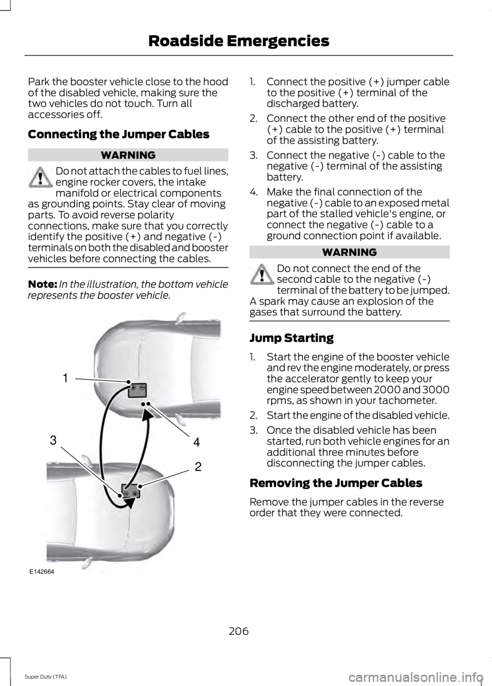
vehicles before connecting the cables. Note:
In the illustration, the bottom vehicle
represents the booster vehicle. 1.
Connect the positive (+) jumper cable
to the positive (+) terminal of the
discharged battery.
2. Connect the other end of the positive (+) cable to the positive (+) terminal
of the assisting battery.
3. Connect the negative (-) cable to the negative (-) terminal of the assisting
battery.
4. Make the final connection of the negative (-) cable to an exposed metal
part of the stalled vehicle's engine, or
connect the negative (-) cable to a
ground connection point if available. WARNING
Do not connect the end of the
second cable to the negative (-)
terminal of the battery to be jumped.
A spark may cause an explosion of the
gases that surround the battery. Jump Starting
1.
Start the engine of the booster vehicle
and rev the engine moderately, or press
the accelerator gently to keep your
engine speed between 2000 and 3000
rpms, as shown in your tachometer.
2. Start the engine of the disabled vehicle.
3. Once the disabled vehicle has been started, run both vehicle engines for an
additional three minutes before
disconnecting the jumper cables.
Removing the Jumper Cables
Remove the jumper cables in the reverse
order that they were connected.
206
Super Duty (TFA) Roadside Emergencies4
2
1
3
E142664
Page 214 of 460

In the CAMVAP program, impartial
third-party arbitrators conduct hearings at
mutually convenient times and places in
an informal environment. These impartial
arbitrators review the positions of the
parties, make decisions and, when
appropriate, render awards to resolve
disputes. CAMVAP decisions are fast, fair,
and final as the arbitrator
’s award is
binding on both you and Ford of Canada.
CAMVAP services are available in all
Canadian territories and provinces. For
more information, without charge or
obligation, call your CAMVAP Provincial
Administrator directly at 1-800-207-0685
or visit www.camvap.ca.
GETTING ASSISTANCE
OUTSIDE THE U.S. AND
CANADA
Before exporting your vehicle to a foreign
country, contact the appropriate foreign
embassy or consulate. These officials can
inform you of local vehicle registration
regulations and where to find unleaded
fuel.
If you cannot find unleaded fuel or can only
get fuel with an anti-knock index lower
than is recommended for your vehicle,
contact our Customer Relationship Center.
The use of leaded fuel in your vehicle
without proper conversion may damage
the effectiveness of your emission control
system and may cause engine knocking or
serious engine damage. Ford Motor
Company or Ford of Canada is not
responsible for any damage caused by use
of improper fuel. Using leaded fuel may
also result in difficulty importing your
vehicle back into the United States. If your vehicle must be serviced while you
are traveling or living in Asia-Pacific Region,
Sub-Saharan Africa, U.S. Virgin Islands,
Central America, the Caribbean, and Israel,
contact the nearest authorized dealer. If
the authorized dealer cannot help you,
contact:
FORD MOTOR COMPANY
FORD EXPORT OPERATIONS & GLOBAL
INITIATIVES
Customer Relationship Center
1555 Fairlane Drive
Fairlane Business Park #3
Allen Park, Michigan 48101
U.S.A.
Telephone: (313) 594-4857
Fax: (313) 390-0804
Email: [email protected]
For customers in Guam, the
Commonwealth of the Northern Mariana
Islands (CNMI), America Samoa, and the
U.S. Virgin Islands, please feel free to call
our Toll-Free Number: (800) 841-FORD
(3673).
If your vehicle must be serviced while you
are traveling or living in Puerto Rico,
contact the nearest authorized dealer. If
the authorized dealer cannot help you,
contact:
FORD MOTOR COMPANY
FORD EXPORT OPERATIONS & GLOBAL
INITIATIVES
Customer Relationship Center
1555 Fairlane Drive
Fairlane Business Park #3
Allen Park, Michigan 48101
U.S.A.
Telephone: (800) 841-FORD (3673)
FAX: (313) 390-0804
Email: [email protected]
www.ford.com.pr
If your vehicle must be serviced while you
are traveling or living in the Middle East,
contact the nearest authorized dealer. If
the authorized dealer cannot help you,
contact:
211
Super Duty (TFA) Customer Assistance
Page 218 of 460

FUSE SPECIFICATION CHART
Power Distribution Box
WARNINGS
Always disconnect the battery before
servicing high current fuses.
To reduce risk of electrical shock,
always replace the cover to the
power distribution box before
reconnecting the battery or refilling fluid
reservoirs. The power distribution box is located in
the engine compartment. It has
high-current fuses that protect your
vehicle's main electrical systems from
overloads.
If you disconnect and reconnect the
battery, you will need to reset some
features. See Changing the 12V Battery
(page 235).
Protected components
Fuse amp rating
Fuse or relay number
Blower motor
Relay
1
Not used
—
2
Urea heaters (diesel engine)
Relay
3
Not used
—
4
Rear window defroster, Heated mirrors
Relay
5
Not used
—
6
Rear window defroster, Heated mirrors
50A*
7
Passenger seat
30A*
8
Driver seat
30A*
9
Not used
—
10
Not used
—
11
215
Super Duty (TFA) FusesE163101
Page 219 of 460

Protected components
Fuse amp rating
Fuse or relay number
Driver smart window motor
30A*
12
Not used
—
13
Not used
—
14
Fuel pump (diesel engine)
Diode
15
Not used
—
16
Heated mirror
15A**
17
Not used
—
18
Not used
—
19
Not used
—
20
Not used
—
21
Trailer tow electric brake
30A*
22
Blower motor
40A*
23
Not used
—
24
Wipers
30A*
25
Trailer tow park lamps
30A*
26
Urea heaters (diesel engine)
25A*
27
Buss bar
—
28
Trailer tow park lamps
Relay
29
A/C clutch
Relay
30
Wipers
Relay
31
Not used
—
32
Vehicle power 1
15A**
33
Vehicle power 2 (diesel engine)
15A**
34
Vehicle power 2 (gas engine)
20A**
Vehicle power 3
10A**
35
Vehicle power 4 (diesel engine)
15A**
36
Vehicle power 4 (gas engine)
20A**
216
Super Duty (TFA) Fuses
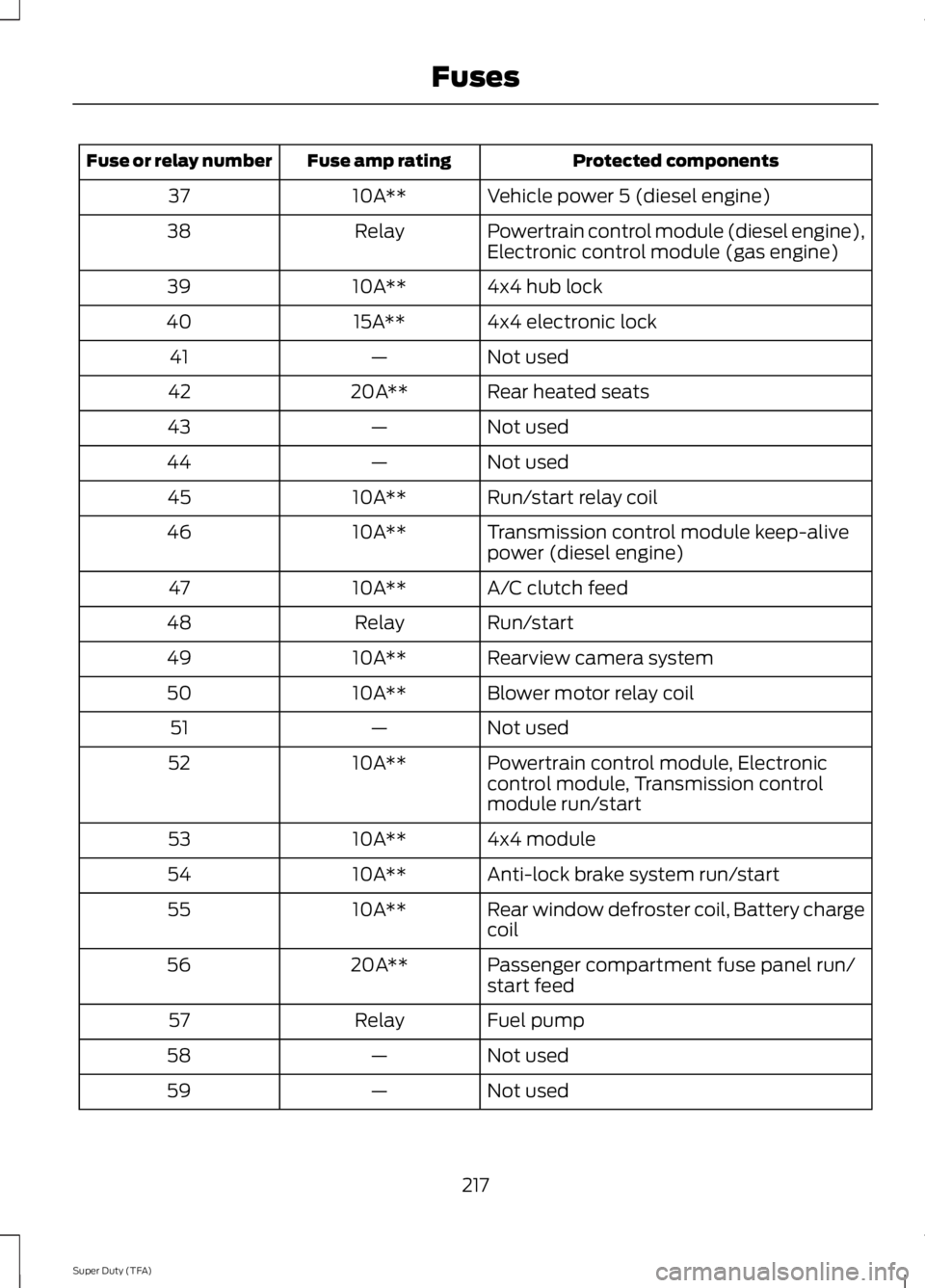
Page 220 of 460

Protected components
Fuse amp rating
Fuse or relay number
Vehicle power 5 (diesel engine)
10A**
37
Powertrain control module (diesel engine),
Electronic control module (gas engine)
Relay
38
4x4 hub lock
10A**
39
4x4 electronic lock
15A**
40
Not used
—
41
Rear heated seats
20A**
42
Not used
—
43
Not used
—
44
Run/start relay coil
10A**
45
Transmission control module keep-alive
power (diesel engine)
10A**
46
A/C clutch feed
10A**
47
Run/start
Relay
48
Rearview camera system
10A**
49
Blower motor relay coil
10A**
50
Not used
—
51
Powertrain control module, Electronic
control module, Transmission control
module run/start
10A**
52
4x4 module
10A**
53
Anti-lock brake system run/start
10A**
54
Rear window defroster coil, Battery charge
coil
10A**
55
Passenger compartment fuse panel run/
start feed
20A**
56
Fuel pump
Relay
57
Not used
—
58
Not used
—
59
217
Super Duty (TFA) Fuses