Page 255 of 460

Note:
Industrial-strength or heavy-duty
cleaners in combination with brush agitation
to remove brake dust and dirt, could wear
away the clear coat finish over a period time.
Note: Do not use hydrofluoric acid-based
or high caustic-based wheel cleaners, steel
wool, fuels or strong household detergents.
Note: If you intend parking your vehicle for
an extended period after cleaning the
wheels with a wheel cleaner, drive your
vehicle for a few minutes before doing so.
This will reduce the risk of increased
corrosion of the brake discs.
Alloy wheels and wheel covers are coated
with a clear coat paint finish. To maintain
their condition we recommend that you:
• Clean the wheels weekly using
Motorcraft Wheel and Tire Cleaner.
Apply using manufacturer's
instructions.
• Use a sponge to remove heavy
deposits of dirt and brake dust
accumulation.
• Rinse thoroughly with a strong stream
of water when you have completed the
cleaning process.
• To remove tar and grease, use
Motorcraft Bug and Tar Remover.
VEHICLE STORAGE
If you plan on storing your vehicle for an
extended period of time (30 days or more),
read the following maintenance
recommendations to make sure your
vehicle stays in good operating condition.
All motor vehicles and their components
were engineered and tested for reliable,
regular driving. Long term storage under
various conditions may lead to component
degradation or failure unless specific
precautions are taken to preserve the
components. General
•
Store all vehicles in a dry, ventilated
place.
• Protect from sunlight, if possible.
• If vehicles are stored outside, they
require regular maintenance to protect
against rust and damage.
Body
• Wash your vehicle thoroughly to
remove dirt, grease, oil, tar or mud from
exterior surfaces, rear-wheel housing
and underside of front fenders.
• Periodically wash your vehicle stored
in exposed locations.
• Touch-up exposed or primed metal to
prevent rust.
• Cover chrome and stainless steel parts
with a thick coat of auto wax to prevent
discoloration. Re-wax as necessary
when your vehicle is washed.
• Lubricate all hood, door and trunk lid
hinges, and latches with a light grade
oil.
• Cover interior trim to prevent fading.
• Keep all rubber parts free from oil and
solvents.
Engine
• The engine oil and filter should be
changed prior to storage, as used
engine oil contain contaminates that
may cause engine damage.
• Start the engine every 15 days. Run at
fast idle until it reaches normal
operating temperature
• With your foot on the brake, shift
through all the gears while the engine
is running.
252
Super Duty (TFA) Vehicle Care
Page 281 of 460

•
To reduce the chances of interference
from another vehicle, perform the
system reset procedure at least three
feet (one meter) away from another
Ford Motor Company vehicle
undergoing the system reset procedure
at the same time.
• Do not wait more than two minutes
between resetting each tire sensor or
the system will time-out and the entire
procedure will have to be repeated on
all four wheels.
• A double horn will sound indicating the
need to repeat the procedure.
Performing the System Reset Procedure
Read the entire procedure before
attempting.
1. Drive the vehicle above 20 mph (32 km/h) for at least two minutes, then
park in a safe location where you can
easily get to all four tires and have
access to an air pump.
2. Place the ignition in the off position and
keep the key in the ignition.
3. Cycle the ignition to the on position with the engine off.
4. Turn the hazard flashers on then off three times. You must accomplish this
within 10 seconds. If the reset mode
has been entered successfully, the horn
will sound once, the system indicator
will flash and a message is shown in
the information display. If this does not
occur, please try again starting at Step
2. If after repeated attempts to enter
the reset mode, the horn does not
sound, the system indicator does not
flash and no message is shown in the
information display, seek service from
your authorized dealer. 5. Train the tire pressure monitoring
system sensors in the tires using the
following system reset sequence
starting with the left front tire in the
following clockwise order: Left front
(driver's side front tire), Right front
(passenger's side front tire), Right rear
(passenger's side rear tire), Left rear
(driver's side rear tire)
6. Remove the valve cap from the valve stem on the left front tire. Decrease the
air pressure until the horn sounds.
Note: The single horn chirp confirms
that the sensor identification code has
been learned by the module for this
position. If a double horn is heard, the
reset procedure was unsuccessful, and
you must repeat it.
7. Remove the valve cap from the valve stem on the right front tire. Decrease
the air pressure until the horn sounds.
8. Remove the valve cap from the valve stem on the right rear tire. Decrease the
air pressure until the horn sounds.
9. Remove the valve cap from the valve stem on the left rear tire. Decrease the
air pressure until the horn sounds.
Training is complete after the horn
sounds for the last tire trained (driver's
side rear tire), the system indicator
stops flashing, and a message is shown
in the information display.
10. Turn the ignition off. If two short horn
beeps are heard, the reset procedure
was unsuccessful and you must
repeat it. If after repeating the
procedure and two short beeps are
heard when the ignition is turned to
off, seek assistance from your
authorized dealer.
278
Super Duty (TFA) Wheels and Tires
Page 284 of 460
Location
Tool
SuperCab: Under rear bench seat onpassenger side
Regular cab: Fastened to floor behind driver seat
Jack handle, lug wrench, lug wrench exten-
sion (only available on dual rear wheel
vehicles) and wheel chock (only available
on single rear wheel vehicles equipped with a diesel engine) SuperCab: Fastened to floor under rear seat
Crew Cab: Fastened to floor behind rear seat at driver side
In the glove box
Key and spare tire lock
Removing the Spare Tire (With
Spare Tire Carrier Only)
The following tools are required to remove
the spare tire: One handle extension and two typical
extensions. To assemble, align the button
with the hole and slide the parts together.
To disconnect, press the button and pull
apart. One wheel nut wrench. Slide over the
square end of the jack handle.
Note:
For vehicles with dual rear wheels,
insert the lug wrench extension into the lug
wrench to reach the lug nuts.
281
Super Duty (TFA) Wheels and TiresE162795 E162796 E162797
Page 286 of 460

WARNINGS
Do not attempt to change a tire on
the side of the vehicle close to
moving traffic. Pull far enough off the
road to avoid the danger of being hit when
operating the jack or changing the wheel. Always use the jack provided as
original equipment with your vehicle.
If using a jack other than the one
provided as original equipment with your
vehicle, make sure the jack capacity is
adequate for the vehicle weight, including
any vehicle cargo or modifications. Note:
Passengers should not remain in the
vehicle when the vehicle is being jacked.
Park on a level surface, set the parking
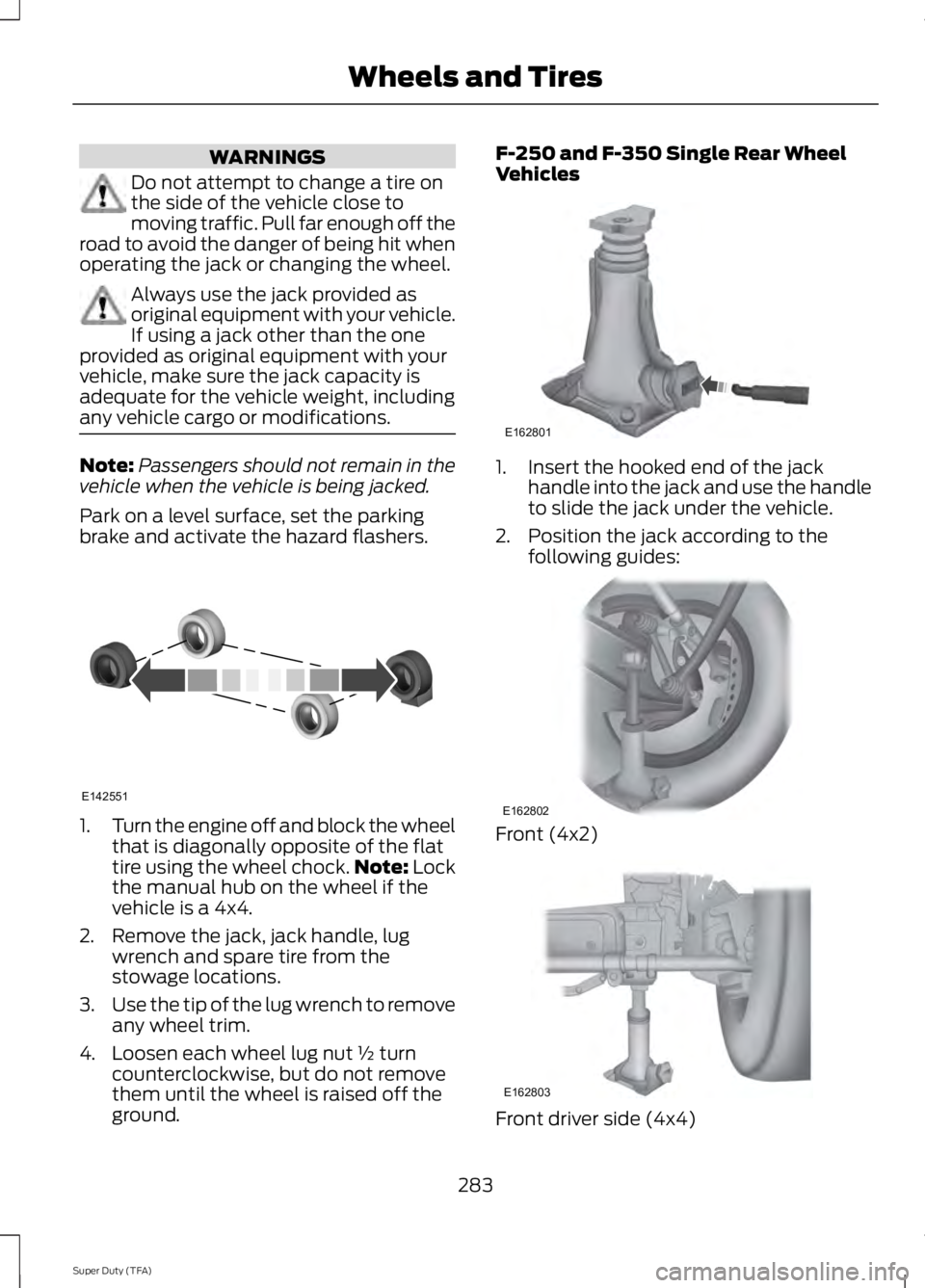
brake and activate the hazard flashers. 1.
Turn the engine off and block the wheel
that is diagonally opposite of the flat
tire using the wheel chock. Note: Lock
the manual hub on the wheel if the
vehicle is a 4x4.
2. Remove the jack, jack handle, lug wrench and spare tire from the
stowage locations.
3. Use the tip of the lug wrench to remove
any wheel trim.
4. Loosen each wheel lug nut ½ turn counterclockwise, but do not remove
them until the wheel is raised off the
ground. F-250 and F-350 Single Rear Wheel
Vehicles
1. Insert the hooked end of the jack
handle into the jack and use the handle
to slide the jack under the vehicle.
2. Position the jack according to the following guides: Front (4x2)
Front driver side (4x4)
283
Super Duty (TFA) Wheels and TiresE142551 E162801 E162802 E162803
Page 295 of 460
ENGINE SPECIFICATIONS
6.8L V10 Engine
6.2L V8 Engine
Engine
413
378
Cubic inches
Minimum 87 octane
Minimum 87 octane
Required fuel
1-6-5-10-2-7-3-8-4-9
1-5-4-8-6-3-7-2
Firing order
Coil on plug
Coil on plug
Ignition system
0.039-0.043 inch (1.00-1.10mm)
0.041-0.047 inch (1.04-1.20
mm)
Spark plug gap
9.2:1
9.8:1
Compression ratio
Drivebelt Routing
6.2L Engines 6.8L Engines with A/C
6.8L Engines without A/C
292
Super Duty (TFA) Capacities and SpecificationsE163761 E163762 E163763
Page 296 of 460
MOTORCRAFT PARTS
6.8L V10 engine
6.2L V8 engine
Component
FA-1883
FA-1883
Air filter element
FL-820-S
FL-820-S
Oil filter
BXT-65-650
BXT-65-650
Battery (standard)
BXT-65-750
BXT-65-750
Battery (optional)
HJFS-24FP/SP-509
CYFS12FP/SP-526
Spark plugs-platinum 1
FS-104
FS-104
Seat filter
WW-2201-P
WW-2201-P
Windshield wiper blade
1 For spark plug replacement, see an authorized dealer. Replace the spark plugs at the
appropriate intervals. See Scheduled Maintenance (page 430).
Note: Replace the spark plugs with ones that meet Ford material and design specifications
for your vehicle, such as Motorcraft or equivalent replacement parts. The customer warranty
may be void for any damage to the engine if such spark plugs are not used.
293
Super Duty (TFA) Capacities and Specifications
Page 297 of 460
VEHICLE IDENTIFICATION
NUMBER
The vehicle identification number is
located on the left-hand side of the
instrument panel.
Please note that in the graphic, XXXX is
representative of your vehicle identification
number.
The Vehicle Identification Number contains
the following information:
World manufacturer identifier
A
Brake system, Gross Vehicle
Weight Rating, Restraint Devices
and their locations
B Make, vehicle line, series, body
type
C
Engine type
D
Check digit
E
Model year
F
Assembly plant
G
Production sequence number
H
VEHICLE CERTIFICATION
LABEL 294
Super Duty (TFA) Capacities and SpecificationsE142476 E142477 E167469
Page 299 of 460

TECHNICAL SPECIFICATIONS
Ford part number /
Ford specification
Ford part name or
equivalent
Capacity
Item
XY-80W-90–QL /
Motorcraft SAE
80W-90 Premium
Rear Axle Lubricant
5.8 pints (2.8L)
Front axle
WSP-M2C197–A
XG-11 /
High Temperature
4X4 Front Axle and Wheel Bearing Grease
—
Spindle bearing
WSS-M1C267-A1
XY-75W140–QL (U.S.) /
Motorcraft SAE
75W-140 Synthetic
Rear Axle Lubricant
6.9 pints (3.3L)
Rear axle - F-250/350
(10.50 inch axle) 1
WSL-M2C192-A
CXY-75W140-1L (Canada) /
WSL-M2C192-A
XY-75W90–QLS /
Motorcraft SAE
75W-90 Synthetic
Rear Axle Lubricant
8.5 pints (4.0L)
Rear axle - F-350 (Dana
M80) WSS–M2C918–A
XY-75W140–QL (U.S.) /
Motorcraft SAE
75W-140 Synthetic
Rear Axle Lubricant
14.0 pints (6.6L)
Rear axle - F-450/550 (Dana S110/S130) WSL-M2C192-A
CXY-75W140-1L (Canada) /
WSL-M2C192-A
PM-20 / WSS- M6C65-A1
Motorcraft High
Performance DOT 3 LV Motor Vehicle Brake Fluid
Between MIN/
MAX on brakefluid reservoir
Brake fluid
2
PM-20 / WSS-M6C65-A2
Motorcraft High
Performance DOT 4 LV Motor Vehicle Brake Fluid
VC-3DIL-B (U.S.) /
Motorcraft Orange
Antifreeze/Coolant Prediluted
21.3 quarts
(20.2L)
Engine coolant (6.2L
V8)3
WSS-M97B44-D2
CVC-3DIL-B(Canada) /
WSS-M97B44-D2
296
Super Duty (TFA) Capacities and Specifications