2014 FORD F SERIES MOTORHOME AND COMMERCIAL CHASSIS fuel cap
[x] Cancel search: fuel capPage 55 of 143
Preparing Your Vehicle
Note:Do not attempt to push-start yourautomatic transmission vehicle. Automatictransmissions do not have push-startcapability. Attempting to push-start avehicle with an automatic transmission maycause transmission damage.
Note:Use only a 12-volt supply to start yourvehicle.
Note:Do not disconnect the battery of thedisabled vehicle as this could damage thevehicle's electrical system.
Park the booster vehicle close to the hoodof the disabled vehicle, making sure thetwo vehicles do not touch. Turn allaccessories off.
Connecting the Jumper Cables
WARNING
Do not attach the cables to fuel lines,engine rocker covers, the intakemanifold or electrical componentsas grounding points. Stay clear of movingparts. To avoid reverse polarityconnections, make sure that you correctlyidentify the positive (+) and negative (-)terminals on both the disabled and boostervehicles before connecting the cables.
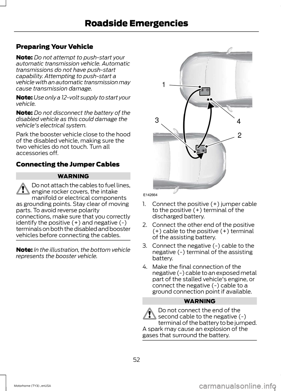
Note:In the illustration, the bottom vehiclerepresents the booster vehicle.
1.Connect the positive (+) jumper cableto the positive (+) terminal of thedischarged battery.
2.Connect the other end of the positive(+) cable to the positive (+) terminalof the assisting battery.
3.Connect the negative (-) cable to thenegative (-) terminal of the assistingbattery.
4.Make the final connection of thenegative (-) cable to an exposed metalpart of the stalled vehicle's engine, orconnect the negative (-) cable to aground connection point if available.
WARNING
Do not connect the end of thesecond cable to the negative (-)terminal of the battery to be jumped.A spark may cause an explosion of thegases that surround the battery.
52Motorhome (TY3) , enUSARoadside Emergencies4213E142664
Page 64 of 143
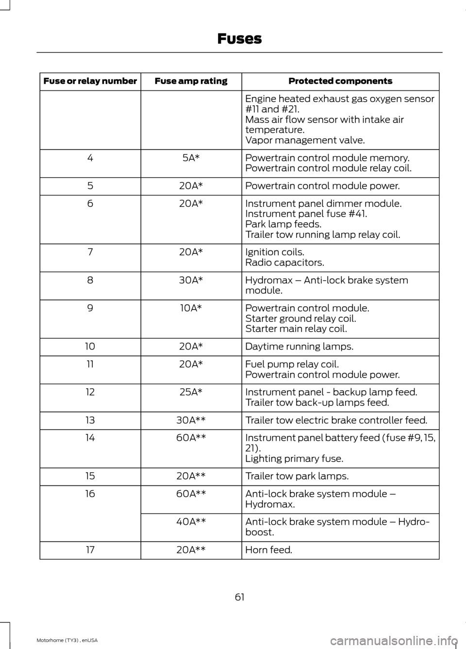
Protected componentsFuse amp ratingFuse or relay number
Engine heated exhaust gas oxygen sensor#11 and #21.Mass air flow sensor with intake airtemperature.Vapor management valve.
Powertrain control module memory.5A*4Powertrain control module relay coil.
Powertrain control module power.20A*5
Instrument panel dimmer module.20A*6Instrument panel fuse #41.Park lamp feeds.Trailer tow running lamp relay coil.
Ignition coils.20A*7Radio capacitors.
Hydromax – Anti-lock brake systemmodule.30A*8
Powertrain control module.10A*9Starter ground relay coil.Starter main relay coil.
Daytime running lamps.20A*10
Fuel pump relay coil.20A*11Powertrain control module power.
Instrument panel - backup lamp feed.25A*12Trailer tow back-up lamps feed.
Trailer tow electric brake controller feed.30A**13
Instrument panel battery feed (fuse #9, 15,21).60A**14
Lighting primary fuse.
Trailer tow park lamps.20A**15
Anti-lock brake system module –Hydromax.60A**16
Anti-lock brake system module – Hydro-boost.40A**
Horn feed.20A**17
61Motorhome (TY3) , enUSAFuses
Page 78 of 143
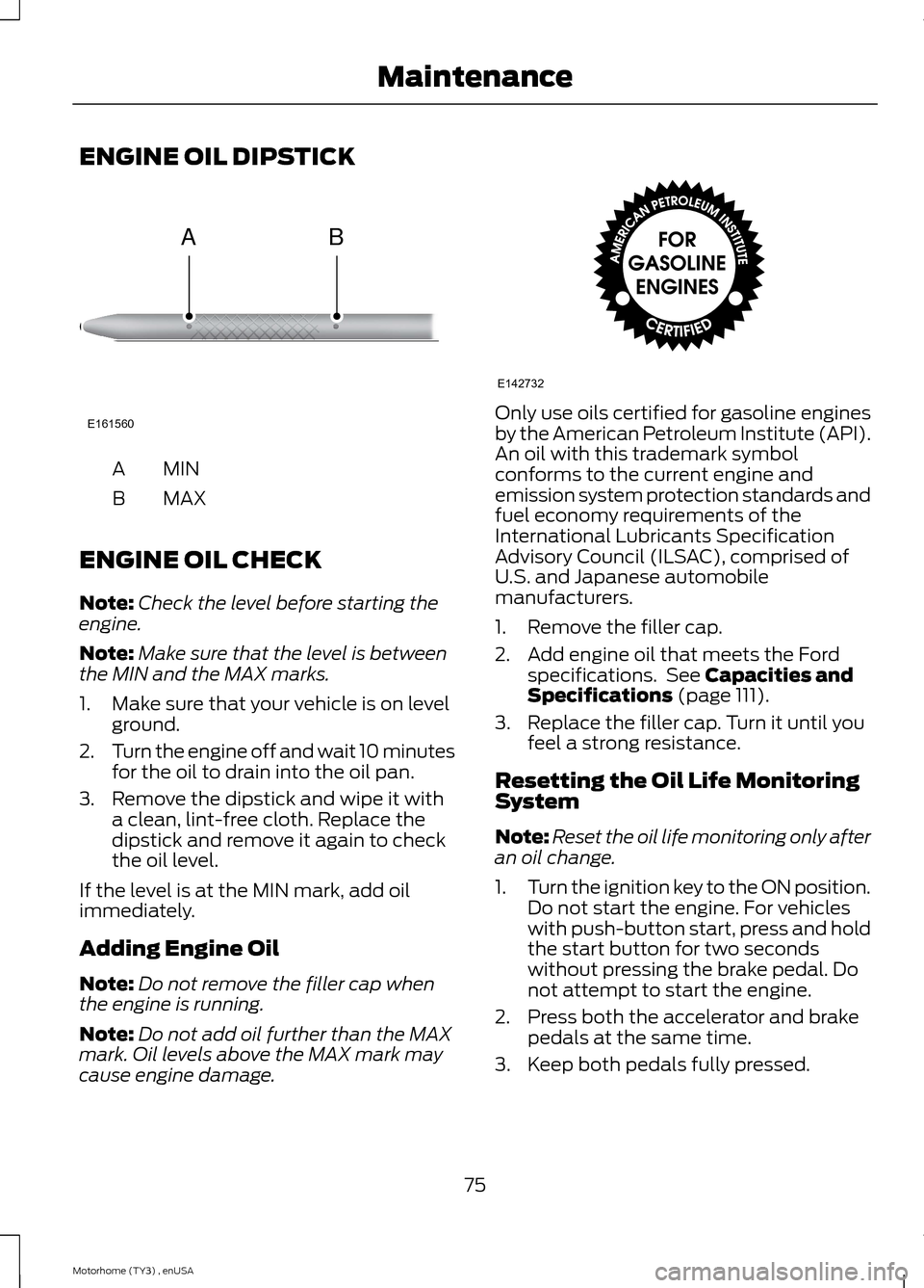
ENGINE OIL DIPSTICK
MINA
MAXB
ENGINE OIL CHECK
Note:Check the level before starting theengine.
Note:Make sure that the level is betweenthe MIN and the MAX marks.
1.Make sure that your vehicle is on levelground.
2.Turn the engine off and wait 10 minutesfor the oil to drain into the oil pan.
3.Remove the dipstick and wipe it witha clean, lint-free cloth. Replace thedipstick and remove it again to checkthe oil level.
If the level is at the MIN mark, add oilimmediately.
Adding Engine Oil
Note:Do not remove the filler cap whenthe engine is running.
Note:Do not add oil further than the MAXmark. Oil levels above the MAX mark maycause engine damage.
Only use oils certified for gasoline enginesby the American Petroleum Institute (API).An oil with this trademark symbolconforms to the current engine andemission system protection standards andfuel economy requirements of theInternational Lubricants SpecificationAdvisory Council (ILSAC), comprised ofU.S. and Japanese automobilemanufacturers.
1.Remove the filler cap.
2.Add engine oil that meets the Fordspecifications. See Capacities andSpecifications (page 111).
3.Replace the filler cap. Turn it until youfeel a strong resistance.
Resetting the Oil Life MonitoringSystem
Note:Reset the oil life monitoring only afteran oil change.
1.Turn the ignition key to the ON position.Do not start the engine. For vehicleswith push-button start, press and holdthe start button for two secondswithout pressing the brake pedal. Donot attempt to start the engine.
2.Press both the accelerator and brakepedals at the same time.
3.Keep both pedals fully pressed.
75Motorhome (TY3) , enUSAMaintenanceE161560AB E142732
Page 86 of 143
4.Check the fluid level on the dipstick. Itshould be between the arrows in theFULL range on the side of the dipstickwith the words MAX. HOT at the top.Do not add fluid if the level is withinthis range.
5.If the fluid is low, add fluid in smallamounts, continuously checking thelevel until it reaches the FULL range.Be sure to put the dipstick back in thereservoir.
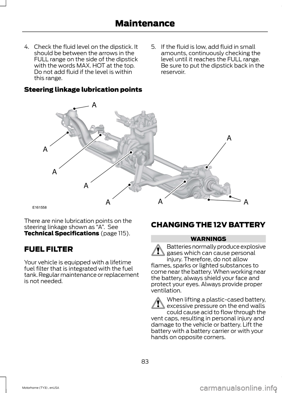
Steering linkage lubrication points
There are nine lubrication points on thesteering linkage shown as “A”. SeeTechnical Specifications (page 115).
FUEL FILTER
Your vehicle is equipped with a lifetimefuel filter that is integrated with the fueltank. Regular maintenance or replacementis not needed.
CHANGING THE 12V BATTERY
WARNINGS
Batteries normally produce explosivegases which can cause personalinjury. Therefore, do not allowflames, sparks or lighted substances tocome near the battery. When working nearthe battery, always shield your face andprotect your eyes. Always provide properventilation.
When lifting a plastic-cased battery,excessive pressure on the end wallscould cause acid to flow through thevent caps, resulting in personal injury anddamage to the vehicle or battery. Lift thebattery with a battery carrier or with yourhands on opposite corners.
83Motorhome (TY3) , enUSAMaintenanceE161558AAAAAAAA
Page 88 of 143
•The transmission must relearn itsadaptive strategy. As a result of this,the transmission may shift firmly. Thisoperation is considered normal and willnot affect function or durability of thetransmission. Over time the adaptivelearning process will fully updatetransmission operation to its optimumshift feel.
•The clock and the preset radio stationsmust be reset once the battery isreconnected.
•Your vehicle’s engine is electronicallycontrolled by a computer, some controlconditions are maintained by powerfrom the battery, the engine mustrelearn its idle and fuel trim strategy.
When the battery is disconnected or a newbattery is installed, begin the batteryrelearn process:
1.With the vehicle at a complete stop,set the parking brake.
2.Put the gearshift lever in P (Park), turnoff all accessories and start the engine.
3.Run the engine until it reaches normaloperating temperature.
4.Allow the engine to idle for at least oneminute.
5.Turn the A/C on and allow the engineto idle for at least one minute.
6.Drive the vehicle to complete therelearning process.
•The vehicle may need to be drivento relearn the idle and fuel trimstrategy.
CHANGING THE ENGINE AIR
FILTER
WARNING
To reduce the risk of vehicle damageand personal burn injuries, do notstart your engine with the air cleanerremoved and do not remove it while theengine is running.
Change the air filter element at the properinterval. See Scheduled Maintenance(page 121).
When changing the air filter element, useonly the air filter element listed. SeeCapacities and Specifications (page111).
Note:Failure to use the correct air filterelement may result in severe enginedamage. The customer warranty may bevoid for any damage to the engine if thecorrect air filter element is not used.
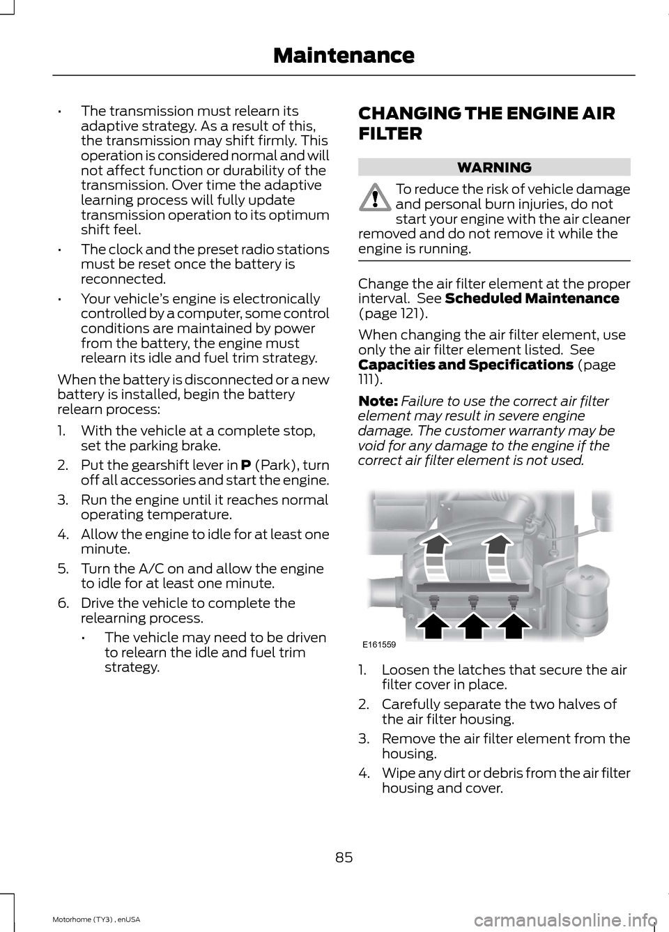
1.Loosen the latches that secure the airfilter cover in place.
2.Carefully separate the two halves ofthe air filter housing.
3.Remove the air filter element from thehousing.
4.Wipe any dirt or debris from the air filterhousing and cover.
85Motorhome (TY3) , enUSAMaintenanceE161559
Page 110 of 143
•Install chains securely, verifying thatthe chains do not touch any wiring,brake lines or fuel lines.
•Drive cautiously. If you hear the chainsrub or bang against your vehicle, stopand retighten the chains. If this doesnot work, remove the chains to preventdamage to your vehicle.
•Remove the tire chains when they areno longer needed. Do not use tirechains on dry roads.
If you have any questions regarding snowchains or cables, please contact yourauthorized dealer.
CHANGING A ROAD WHEEL
If you get a flat tire while driving, do notapply the brake heavily. Instead, graduallydecrease your speed. Hold the steeringwheel firmly and slowly move to a safeplace on the side of the road.
Dissimilar Spare Wheel and TireAssembly Information
WARNING
Failure to follow these guidelinescould result in an increased risk ofloss of vehicle control, injury or death.
If you have a dissimilar spare wheel andtire, then it is intended for temporary useonly. This means that if you need to use it,you should replace it as soon as possiblewith a road wheel and tire assembly thatis the same size and type as the road tiresand wheels that were originally providedby Ford. If the dissimilar spare tire or wheelis damaged, it should be replaced ratherthan repaired.
A dissimilar spare wheel and tire assemblyis defined as a spare wheel and tireassembly that is different in brand, size orappearance from the road tires and wheelsand can be one of three types:
1.T-type mini-spare: This spare tirebegins with the letter T for tire size andmay have Temporary Use Only molded inthe sidewall.
2.Full-size dissimilar spare with labelon wheel: This spare tire has a label onthe wheel that states: THIS WHEEL ANDTIRE ASSEMBLY FOR TEMPORARY USEONLY
When driving with one of the dissimilarspare tires listed above, do not:
•Exceed 50 mph (80 km/h).
•Load the vehicle beyond maximumvehicle load rating listed on the SafetyCompliance Label.
•Tow a trailer.
•Use snow chains on the end of thevehicle with the dissimilar spare tire.
•Use more than one dissimilar spare tireat a time.
•Use commercial car washingequipment.
•Try to repair the dissimilar spare tire.
Use of one of the dissimilar spare tireslisted above at any one wheel location canlead to impairment of the following:
•Handling, stability and brakingperformance.
•Comfort and noise.
•Ground clearance and parking at curbs.
•Winter weather driving capability.
•Wet weather driving capability.
•All-wheel driving capability
3.Full-size dissimilar spare withoutlabel on wheel
107Motorhome (TY3) , enUSAWheels and Tires
Page 114 of 143
ENGINE SPECIFICATIONS
6.8L V10 engineEngine
415Cubic inches
Minimum 87 octaneRequired fuel
1-6-5-10-2-7-3-8-4-9Firing order
Coil on plugIgnition system
0.039-0.043 inch (1.00-1.10mm)Spark plug gap
9.2:1Compression ratio
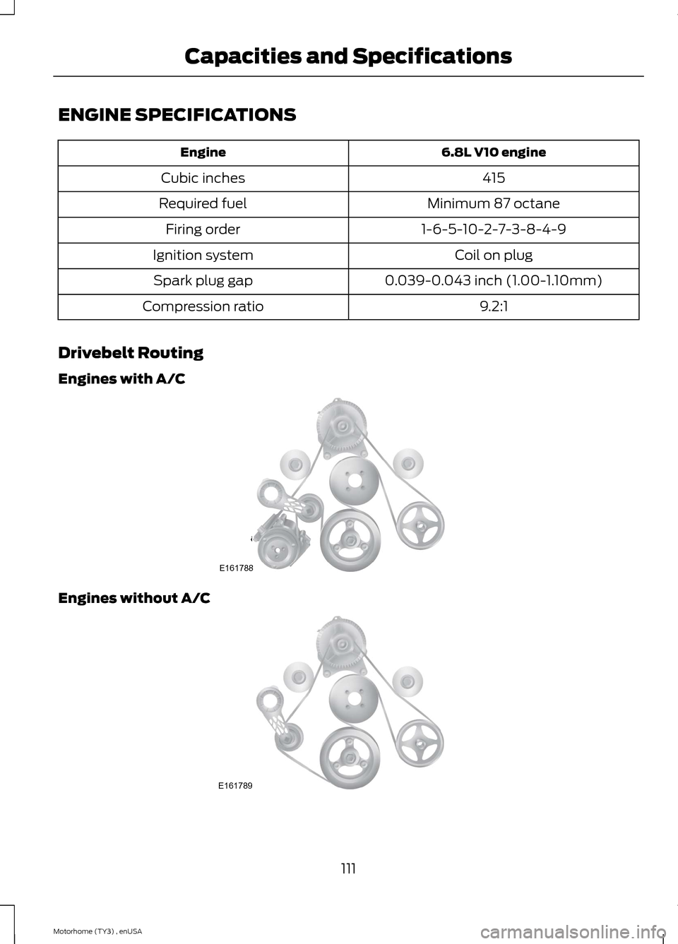
Drivebelt Routing
Engines with A/C
Engines without A/C
111Motorhome (TY3) , enUSACapacities and SpecificationsE161788 E161789
Page 119 of 143
Ford part number /Ford specificationFord part nameor equivalentCapacityItem
XY-75W140-QL(U.S.) /MotorcraftSAE 75W-140Synthetic RearAxle Lubricant
Dana M80 axle4.0 qt (3.9L)Rear axle lubricant9,10
WSL-M2C192-A andGL-5Dana S110 axle8.0 qt (7.6L)
Dana S130 axle7.0 qt (6.6L)
Dana Spicer 17060SaxleCXY-75W140-1L(Canada) /16.0 qt (15.1L)WSL-M2C192-A andGL-5
XG-1-EPremiumLong-LifeGrease
—Transmission, steeringand parking brake link-ages and pivots, brakepedal shaft
ZC-32-A /MotorcraftPremiumWindshieldWasherConcentrateswith Bitterant(U.S.)
Fill as requiredWindshield washer fluidWSB-M8B16-A2
CXC-37-(A, B, D, andF) /MotorcraftPremiumQuality Wind-shield WasherFluid (Canada)
WSB-M8B16-A2
Not applicableNot applicableMotorhomeFuel tank80 gal (303L)
Not applicableNot applicableCommercial chassis40 gal (151L)
YN-19 (U.S.) /Motorcraft R-134a Refri-gerant
1.74 lb (0.79 kg)A/C Refrigerant 11WSH-M17B19-A
CYN16-R (Canada) /WSH-M17B19-A
116Motorhome (TY3) , enUSACapacities and Specifications