Page 202 of 519
HINTS ON DRIVING WITH ANTI-LOCK BRAKES
When the system is operating, the brake pedal will pulse and may travel
further. Maintain pressure on the brake pedal. You may also hear a noise
from the system. This is normal.
The anti-lock braking system will not eliminate the dangers inherent
when:
•you drive too closely to the vehicle in front of you.
•your vehicle is hydroplaning.
•you take corners too fast.
•the road surface is poor.
PARKING BRAKE
WARNING:Always set the parking brake fully and make sure that
the transmission selector lever is securely latched in positionP.
To set the parking brake, press the parking brake pedal down until the
pedal stops.
The brake warning lamp will illuminate and will remain illuminated until
the parking brake is released.
To release, pull the brake release lever located at the lower left side of
the instrument panel.
Brakes201
2014 Expedition(exd)
Owners Guide gf, 1st Printing, June 2013
USA(fus)
Page 203 of 519

PRINCIPLES OF OPERATION
The traction control system helps avoid drive wheel spin and loss of
traction.
If your vehicle begins to slide, the system applies the brakes to individual
wheels and, when needed, reduces engine power at the same time. If the
wheels spin when accelerating on slippery or loose surfaces, the system
reduces engine power in order to increase traction.
USING TRACTION CONTROL
In certain situations (for example, stuck in snow or mud), turning the
traction control off may be beneficial as this allows the wheels to spin
with full engine power. Turn the traction control system off using the
TCS OFFbutton located on the center of the instrument panel.
System indicator lights and messages
WARNING:If a failure has been detected within the Traction
Control System, the stability control light will illuminate steadily.
Verify that the Traction Control System was not manually disabled.
If the stability control light still illuminates steadily, have the system
serviced by an authorized dealer immediately. Operating your vehicle
with Traction Control disabled could lead to an increased risk of loss of
vehicle control, vehicle rollover, personal injury and death.
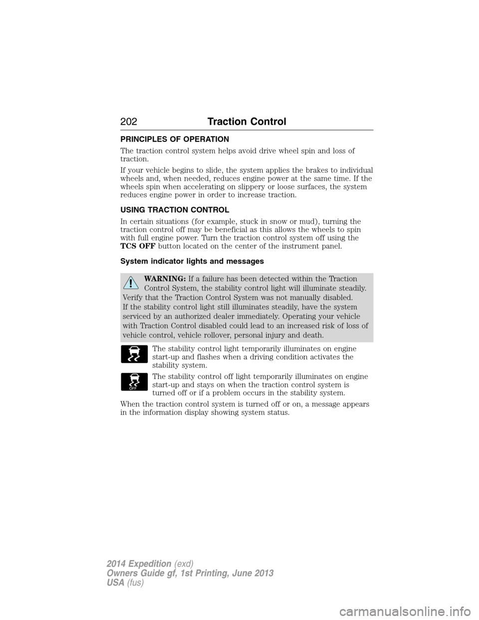
The stability control light temporarily illuminates on engine
start-up and flashes when a driving condition activates the
stability system.
The stability control off light temporarily illuminates on engine
start-up and stays on when the traction control system is
turned off or if a problem occurs in the stability system.
When the traction control system is turned off or on, a message appears
in the information display showing system status.
202Traction Control
2014 Expedition(exd)
Owners Guide gf, 1st Printing, June 2013
USA(fus)
Page 248 of 519

Vehicles Sold in the U.S.: Using Roadside Assistance
Complete the roadside assistance identification card and place it in your
wallet for quick reference. This card is found in the owner’s manual
portfolio in the glove compartment.
U.S. Ford vehicle customers who require Roadside Assistance, call
1-800-241-3673.
If you need to arrange roadside assistance for yourself, Ford Motor
Company will reimburse a reasonable amount for towing to the nearest
dealership within 35 miles (56 kilometers). To obtain reimbursement
information, U.S. Ford vehicle customers call 1-800-241-3673. Customers
will be asked to submit their original receipts.
Vehicles Sold in Canada: Getting Roadside Assistance
Canadian customers who require roadside assistance, call
1–800–665–2006.
Vehicles Sold in Canada: Using Roadside Assistance
For your convenience, you may complete the roadside assistance
identification card found in the centerfold of this warranty guide and
retain for future reference.
Canadian roadside coverage and benefits may differ from the U.S.
coverage. If you require more information, please refer to the coverage
section of your warranty guide, call us in Canada at 1-800-665-2006, or
visit our website at www.ford.ca.
HAZARD WARNING FLASHERS
The hazard flasher control is located on the instrument panel
by the radio. Use it when your vehicle is disabled and is
creating a safety hazard for other motorists.
•Press the flasher control and all front and rear direction signals will
flash.
•Press the flasher control again to turn them off.
Note:With extended use, the flashers may run down your 12–volt
battery.
Roadside Emergencies247
2014 Expedition(exd)
Owners Guide gf, 1st Printing, June 2013
USA(fus)
Page 265 of 519
Fuse or relay
locationFuse amp
ratingProtected circuits
58 15A* Trailer tow backup lamps
59 15A* Heated mirrors
60 — Not used
61 — Fuel pump diode
62 — Not used
63 25A** Electronic fan
64 30A** Moonroof
65 20A** Auxiliary power point
(instrument panel)
66 20A** Auxiliary power point (rear of
center console)
67 40A** Front row climate controlled
seats
68 60A** Anti-lock brake system valves
69 60A** Anti-lock brake system pump
70 30A** Third row power fold seat
71 20A** Auxiliary power point/cigar
lighter
72 20A** Auxiliary power point (right rear
quarter panel)
73 — Not used
74 30A** Driver power seat
75 20A* Vehicle power 1 – powertrain
control module
76 20A* Vehicle power 2 – powertrain
control module
77 15A* Vehicle power4–ignition coils
78 — Not used
79 20A* Vehicle power 3 – powertrain
control module
80 — Not used
81 — Not used
264Fuses
2014 Expedition(exd)
Owners Guide gf, 1st Printing, June 2013
USA(fus)
Page 266 of 519
Fuse or relay
locationFuse amp
ratingProtected circuits
82 — Not used
83 — Not used
84 — Not used
85 — Wiper motor relay
* Mini Fuses ** Cartridge Fuses
Passenger Compartment Fuse Panel
The fuse panel is located under the right-hand side of the instrument
panel.
To remove the trim panel for access
to the fuse box, pull the panel toward
you and swing it out away from the
side and remove it. To reinstall it, line
up the tabs with the grooves on the
panel, then push it shut.
To remove the fuse box cover, press in the tabs on both sides of the
cover, then pull the cover off.
To reinstall the fuse box cover, place the top part of the cover on the
fuse panel, then push the bottom part of the cover until you hear it click
shut. Gently pull on the cover to make sure it is seated properly.
Fuses265
2014 Expedition(exd)
Owners Guide gf, 1st Printing, June 2013
USA(fus)
Page 268 of 519
Fuse or relay
locationFuse amp
ratingProtected circuits
11 10A Not used (spare)
12 7.5A Power mirrors, Driver seat
memory switch
13 5A Not used (spare)
14 10A Power liftgate module – keep-alive
power
15 10A Climate control, Global positioning
satellite module
16 15A Not used (spare)
17 20A Door locks, Liftgate release,
Liftglass release
18 20A Second row heated seats
19 25A Rear wiper
20 15A Adjustable pedals, Datalink
21 15A Fog lamps
22 15A Park lamps
23 15A High beam headlamps
24 20A Horn
25 10A Demand lamps, Glove box, Visor
26 10A Instrument panel cluster
27 20A Ignition switch
28 5A Radio
29 5A Instrument panel cluster
30 5A Not used (spare)
31 10A Not used (spare)
32 10A Airbag module
33 10A Trailer brake logic
34 5A Not used (spare)
35 10A Rear park assist, 4x4, rear video
camera, 2nd row heated seats
36 5A Passive anti-theft system
37 10A Climate control
Fuses267
2014 Expedition(exd)
Owners Guide gf, 1st Printing, June 2013
USA(fus)
Page 271 of 519
Working with the Engine Off
1. Set the parking brake and shift toP(Park).
2. Turn off the engine and remove the key (if equipped).
3. Block the wheels.
Working with the Engine On
WARNING:To reduce the risk of vehicle damage or personal
burn injuries, do not start your engine with the air cleaner
removed and do not remove it while the engine is running.
1. Set the parking brake and shift to positionP.
2. Block the wheels.
OPENING AND CLOSING THE HOOD
1. Inside the vehicle, pull the hood
release handle located under the
bottom of the instrument panel.
2. Go to the front of the vehicle and
release the auxiliary latch that is
located under the front center of
the hood.
3. Lift the hood until the lift
cylinders hold it open.
B
R
A
K
E
270Maintenance
2014 Expedition(exd)
Owners Guide gf, 1st Printing, June 2013
USA(fus)
Page 293 of 519

BULB SPECIFICATION CHART
Replacement bulbs are specified in the chart below. Headlamp bulbs
must be marked with an authorized “D.O.T.” for North America to ensure
lamp performance, light brightness and pattern and safe visibility. The
correct bulbs will not damage the lamp assembly or void the lamp
assembly warranty and will provide quality bulb burn time.
Function Number of bulbs Trade number
Headlamps (low and
high-beam)2 H13/9008
Front side marker 2 194
Front park/turn lamps 2 3157 A
Fog lamps 2 9140
Front row map lamps 2 W5W
Front row map/dome
lamps3 578
Rear cargo lamp 1 578
2nd row reading lamp 2 W5W
Turn/tail/brake/side
marker lamps2 3157K
Backup lamp 2 921
Approach/mirror
turn signal lamps
(if equipped)2 906
Mirror approach lamps
– non turn signal
(if equipped)2 *See your dealer
License lamp 2 168
Visor vanity lamp -
Slide on rail system
(SOR)2 A6224PF
High-mount brake lamp 5 W5W
All replacement bulbs are clear in color except where noted.
To replace all instrument panel lights - see your authorized dealer
* To obtain replacement approach lamp assembly bulbs, see your
authorized dealer and reference Ford part no. 2L1Z–13B374–BB for the
passenger side mirror and 2L1Z–13B375–BB for the driver side mirror.
292Maintenance
2014 Expedition(exd)
Owners Guide gf, 1st Printing, June 2013
USA(fus)