2014 FIAT FIORINO Owner handbook (in English)
-
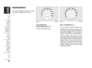
 1
1 -
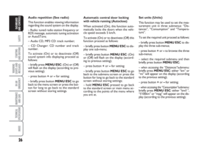
 2
2 -
 3
3 -
 4
4 -
 5
5 -
 6
6 -
 7
7 -
 8
8 -
 9
9 -
 10
10 -
 11
11 -
 12
12 -
 13
13 -
 14
14 -
 15
15 -
 16
16 -
 17
17 -
 18
18 -
 19
19 -
 20
20 -
 21
21 -
 22
22 -
 23
23 -
 24
24 -
 25
25 -
 26
26 -
 27
27 -
 28
28 -
 29
29 -
 30
30 -
 31
31 -
 32
32 -
 33
33 -
 34
34 -
 35
35 -
 36
36 -
 37
37 -
 38
38 -
 39
39 -
 40
40 -
 41
41 -
 42
42 -
 43
43 -
 44
44 -
 45
45 -
 46
46 -
 47
47 -
 48
48 -
 49
49 -
 50
50 -
 51
51 -
 52
52 -
 53
53 -
 54
54 -
 55
55 -
 56
56 -
 57
57 -
 58
58 -
 59
59 -
 60
60 -
 61
61 -
 62
62 -
 63
63 -
 64
64 -
 65
65 -
 66
66 -
 67
67 -
 68
68 -
 69
69 -
 70
70 -
 71
71 -
 72
72 -
 73
73 -
 74
74 -
 75
75 -
 76
76 -
 77
77 -
 78
78 -
 79
79 -
 80
80 -
 81
81 -
 82
82 -
 83
83 -
 84
84 -
 85
85 -
 86
86 -
 87
87 -
 88
88 -
 89
89 -
 90
90 -
 91
91 -
 92
92 -
 93
93 -
 94
94 -
 95
95 -
 96
96 -
 97
97 -
 98
98 -
 99
99 -
 100
100 -
 101
101 -
 102
102 -
 103
103 -
 104
104 -
 105
105 -
 106
106 -
 107
107 -
 108
108 -
 109
109 -
 110
110 -
 111
111 -
 112
112 -
 113
113 -
 114
114 -
 115
115 -
 116
116 -
 117
117 -
 118
118 -
 119
119 -
 120
120 -
 121
121 -
 122
122 -
 123
123 -
 124
124 -
 125
125 -
 126
126 -
 127
127 -
 128
128 -
 129
129 -
 130
130 -
 131
131 -
 132
132 -
 133
133 -
 134
134 -
 135
135 -
 136
136 -
 137
137 -
 138
138 -
 139
139 -
 140
140 -
 141
141 -
 142
142 -
 143
143 -
 144
144 -
 145
145 -
 146
146 -
 147
147 -
 148
148 -
 149
149 -
 150
150 -
 151
151 -
 152
152 -
 153
153 -
 154
154 -
 155
155 -
 156
156 -
 157
157 -
 158
158 -
 159
159 -
 160
160 -
 161
161 -
 162
162 -
 163
163 -
 164
164 -
 165
165 -
 166
166 -
 167
167 -
 168
168 -
 169
169 -
 170
170 -
 171
171 -
 172
172 -
 173
173 -
 174
174 -
 175
175 -
 176
176 -
 177
177 -
 178
178 -
 179
179 -
 180
180 -
 181
181 -
 182
182 -
 183
183 -
 184
184 -
 185
185 -
 186
186 -
 187
187 -
 188
188 -
 189
189 -
 190
190 -
 191
191 -
 192
192 -
 193
193 -
 194
194 -
 195
195 -
 196
196 -
 197
197 -
 198
198 -
 199
199 -
 200
200 -
 201
201 -
 202
202 -
 203
203 -
 204
204 -
 205
205 -
 206
206 -
 207
207 -
 208
208 -
 209
209
 64
SAFETY
STARTING
AND DRIVING
WARNING
LIGHTS AND
MESSAGES
IN AN
EMERGENCY
MAINTENANCE
AND CARE
TECHNICAL
SPECIFICATIONS
INDEX
DASHBOARD
AND CONTROLS
BOOT
EMERGENCY OPENING
FROM INSIDE
In case of em")
 65
SAFETY
STARTING
AND DRIVING
WARNING
LIGHTS AND
MESSAGES
IN AN
EMERGENCY
MAINTENANCE
AND CARE
TECHNICAL
SPECIFICATIONS
INDEX
DASHBOARD
AND CONTROLS
REMOVING THE REAR
WINDOW SHELF
(Combi versions)")
 66
SAFETY
STARTING
AND DRIVING
WARNING
LIGHTS AND
MESSAGES
IN AN
EMERGENCY
MAINTENANCE
AND CARE
TECHNICAL
SPECIFICATIONS
INDEX
DASHBOARD
AND CONTROLS
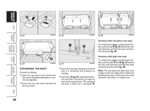
EXPANDING THE BOOT
Proceed as follows:
❒open t")
 67
SAFETY
STARTING
AND DRIVING
WARNING
LIGHTS AND
MESSAGES
IN AN
EMERGENCY
MAINTENANCE
AND CARE
TECHNICAL
SPECIFICATIONS
INDEX
DASHBOARD
AND CONTROLS
REMOVING REAR SEAT
When bulky cargos need to be")
 68
SAFETY
STARTING
AND DRIVING
WARNING
LIGHTS AND
MESSAGES
IN AN
EMERGENCY
MAINTENANCE
AND CARE
TECHNICAL
SPECIFICATIONS
INDEX
DASHBOARD
AND CONTROLS
BONNET
OPENING THE BONNET
Proceed as follows:
�")
 69
SAFETY
STARTING
AND DRIVING
WARNING
LIGHTS AND
MESSAGES
IN AN
EMERGENCY
MAINTENANCE
AND CARE
TECHNICAL
SPECIFICATIONS
INDEX
DASHBOARD
AND CONTROLS
IMPORTANT A label with a description
of the abov")
 70
SAFETY
STARTING
AND DRIVING
WARNING
LIGHTS AND
MESSAGES
IN AN
EMERGENCY
MAINTENANCE
AND CARE
TECHNICAL
SPECIFICATIONS
INDEX
DASHBOARD
AND CONTROLS
HEADLIGHTS
DIRECTING THE BEAM
Correct direction")
 71
SAFETY
STARTING
AND DRIVING
WARNING
LIGHTS AND
MESSAGES
IN AN
EMERGENCY
MAINTENANCE
AND CARE
TECHNICAL
SPECIFICATIONS
INDEX
DASHBOARD
AND CONTROLS
ABS SYSTEM
The vehicle is fitted with an ABS bra")