Page 73 of 210
 72
SAFETY
STARTING
AND DRIVING
WARNING
LIGHTS AND
MESSAGES
IN AN
EMERGENCY
MAINTENANCE
AND CARE
TECHNICAL
SPECIFICATIONS
INDEX
DASHBOARD
AND CONTROLS
If warning light xonly lights
up on the instrume")
72
SAFETY
STARTING
AND DRIVING
WARNING
LIGHTS AND
MESSAGES
IN AN
EMERGENCY
MAINTENANCE
AND CARE
TECHNICAL
SPECIFICATIONS
INDEX
DASHBOARD
AND CONTROLS
If warning light xonly lights
up on the instrument panel
(with a message on the display in
some versions), immediately stop the
vehicle and go to the nearest Fiat
Dealership. Leakage of hydraulic flu-
id from the braking system jeopardis-
es the functionality of the braking sys-
tem, either of the conventional type
or with ABS.
WARNING
EBD failure
EBD failure is indicated by the turning on
of warning lights
>and xon the instru-
ment panel (together with the dedicated
message on the display in some versions)
(see section “Warning lights and mes-
sages”).
In this case, the rear wheels may sudden-
ly lock and the vehicle may swerve. Dri-
ve carefully to the nearest Fiat Dealership
to have the system checked.BRAKE ASSIST
(emergency braking assistance
integral with ESP)
(for versions/markets, where provided)
The system, which cannot be cut out, rec-
ognizes emergency braking (on the ground
of the brake pedal operation speed) and
considerably increases the pressure in the
brake circuit thus supporting the driver to
obtain prompt and effective braking.
Brake Assist is deactivated on the versions
equipped with ESP, in the event of ESP sys-
tem failure (indicated by warning light
áswitching on together with the message
on the multifunction display, for ver-
sions/markets, where provided).
ESP SYSTEM
(Electronic Stability
Program)
(for versions/markets, where provided)
The ESP system is an electronic system
controlling the car stability in the event of
tyre grip loss.
The ESP system is therefore particularly
useful when grip conditions of the road sur-
faces changes.
In addition to the ESP system, ASR system
and Hill Holder,(for versions/markets,
where provided) also the MSR system (ad-
justing the engine braking torque) and the
HBA system (improving the braking force
during emergency braking) are provided.
ABS SYSTEM INTERVENTION
It is signalled by the blinking of the warn-
ing light
áon the instrument panel, to in-
form the driver that the car is in critical
stability and grip conditions.
When the ABS cuts in, and
you feel the brake pedal pul-
sating, do not remove your foot, but
keep it pressed; in doing so you will
stop in the shortest amount of space
possible under the current road con-
ditions.
WARNING
036-082 Fiorino GB 1ed:036-082 Fiorino GB 1ed 30-11-2009 15:47 Pagina 72
Page 74 of 210
 73
SAFETY
STARTING
AND DRIVING
WARNING
LIGHTS AND
MESSAGES
IN AN
EMERGENCY
MAINTENANCE
AND CARE
TECHNICAL
SPECIFICATIONS
INDEX
DASHBOARD
AND CONTROLS
ESP SYSTEM ACTIVATION
The ESP system is automat")
73
SAFETY
STARTING
AND DRIVING
WARNING
LIGHTS AND
MESSAGES
IN AN
EMERGENCY
MAINTENANCE
AND CARE
TECHNICAL
SPECIFICATIONS
INDEX
DASHBOARD
AND CONTROLS
ESP SYSTEM ACTIVATION
The ESP system is automatically activat-
ed when the car is started and cannot be
de-activated.
FAILURE INDICATIONS
In the event of failure, the ESP system is
automatically disconnected, the warning
light
á, comes on with fixed light on the
instrument panel, together with the mes-
sage on the multifunction display (for ver-
sions/markets, where provided) (see sec-
tion “Warning lights and messages”) and
with the button led ASR OFF. In this case
contact a Fiat Dealership as soon as pos-
sible.
Performance of the ESP sys-
tem, in terms of active safe-
ty should not induce the driver to take
pointless and unnecessary risks. The
style of driving must in any case al-
ways be adapted to the conditions of
the road surface, visibility and traffic.
Road safety is always the driver’s re-
sponsibility.
WARNING
HILL HOLDER SYSTEM
This system is an integral part of the ESP
system and it is provided to facilitate start-
ing on slopes.
It will activate automatically with the fol-
lowing conditions:
❒uphill: vehicle stationary on a road with
a gradient of more than 5%, engine run-
ning, brake pressed and gearbox in neu-
tral or gear other than reverse engaged;
❒downhill: vehicle stationary on a road
with a gradient of more than 5%, engine
running, brake pressed and reverse gear
engaged.
At pickup the ESP system control unit will
keep brake force on wheels until reaching
the torque suitable for starting, or in any
case for max. 2 seconds in order to pass
easily from the brake pedal to the accel-
erator pedal.
After two seconds without starting, the
system will deactivate automatically by re-
leasing gradually the brake force.
At releasing, the typical brake disengage-
ment noise indicating that the car is go-
ing to move will be heard.FAILURE INDICATIONS
System failure is indicated by the turning
on of warning light *on the instrument
panel with digital display and warning light
áon the instrument panel with multi-
function display (for versions/markets,
where provided) (see section “Warning
lights and messages”).
IMPORANT The Hill Holder system is not
a parking brake therefore, never leave the
car without having engaged the handbrake,
turned the engine off and engaged the first
speed.
For correct operation of the
ESP and ASR systems, the
tyres must absolutely be of the same
brand and type on all wheels, in per-
fect conditions and, above all, of
type, brand and size specified.
WARNING
036-082 Fiorino GB 1ed:036-082 Fiorino GB 1ed 30-11-2009 15:47 Pagina 73
Page 75 of 210
 74
SAFETY
STARTING
AND DRIVING
WARNING
LIGHTS AND
MESSAGES
IN AN
EMERGENCY
MAINTENANCE
AND CARE
TECHNICAL
SPECIFICATIONS
INDEX
DASHBOARD
AND CONTROLS
MSR system (engine braking
torque control)
It is")
74
SAFETY
STARTING
AND DRIVING
WARNING
LIGHTS AND
MESSAGES
IN AN
EMERGENCY
MAINTENANCE
AND CARE
TECHNICAL
SPECIFICATIONS
INDEX
DASHBOARD
AND CONTROLS
MSR system (engine braking
torque control)
It is an integral part of the ASR system that
in case of sudden gear shifting, cuts in pro-
viding torque to the engine thus prevent-
ing excessive driving wheel drive that, spe-
cially in poor grip conditions, can lead to
loss of stability.
Switching systemon/off
The ASR system switches on automatically
each time the engine is started.
When travelling, the ASR can be switched
off and on again pressing button A-
fig. 101set on the dashboard. When the ASR is switched off this is
shown by the lighting up of the led on the
button and by relevant message on the
multifunction display, for versions/mar-
kets, where provided.
If the ASR is switched off when travelling,
it will turn on again automatically the next
time the engine is started.
When travelling on snowy roads with
snow chains, it may be helpful to turn the
ASR off: in fact, in these conditions, slip-
ping of the driving wheels when moving off
makes it possible to obtain better drive.
For correct operation of the
ESP and ASR systems, the
tyres must absolutely be of the same
brand and type on all wheels, in per-
fect conditions and, above all, of
type, brand and size specified.
WARNING
fig. 101F0T0317m
ASR SYSTEM (Antislip Regulator)
The ASR function controls car drive and
cuts in automatically every time one or
both driving wheels slip.
According to slipping conditions, two dif-
ferent control systems are activated:
❒if slipping involves both driving wheels,
the ASR function intervenes reducing
the power transmitted by the engine;
❒if the slipping involves only one driving
wheel, the ASR system cuts in auto-
matically braking the wheel that is slip-
ping.
The action of the ASR is particularly help-
ful in the following circumstances:
❒ slipping of the inner wheel due to the
effect of dynamic load changes or ex-
cessive acceleration;
❒ too much power transmitted to the
wheels also in relation to the conditions
of the road surface;
❒ acceleration on slippery, snowy or
frozen surfaces;
❒ in the case of loss of grip on a wet sur-
face (aquaplaning).
036-082 Fiorino GB 1ed:036-082 Fiorino GB 1ed 30-11-2009 15:47 Pagina 74
Page 76 of 210
 75
SAFETY
STARTING
AND DRIVING
WARNING
LIGHTS AND
MESSAGES
IN AN
EMERGENCY
MAINTENANCE
AND CARE
TECHNICAL
SPECIFICATIONS
INDEX
DASHBOARD
AND CONTROLS
The performance of the sys-
tem, in terms of act")
75
SAFETY
STARTING
AND DRIVING
WARNING
LIGHTS AND
MESSAGES
IN AN
EMERGENCY
MAINTENANCE
AND CARE
TECHNICAL
SPECIFICATIONS
INDEX
DASHBOARD
AND CONTROLS
The performance of the sys-
tem, in terms of active safe-
ty should not induce the driver to take
pointless and unnecessary risks. The
style of driving must in any case al-
ways be adapted to the conditions of
the road surface, visibility an traffic.
Road safety is always the driver’s re-
sponsibility.
WARNING
For correct operation of the ASR system,
the tyres must absolutely be of the same
brand and type on all wheels, in perfect
conditions and, above all, of type, brand
and size specified.
FAILURE INDICATIONS
In the event of malfunctioning, the ASR
system is automatically disconnected and
the warning light
áwill come with fixed
light on the instrument panel together
with the message on the multifunction dis-
play, for versions/markets, where provid-
ed, (see section “Warning lights and mes-
sages”). In this case contact Fiat Dealer-
ship as soon as possible.
TRACTION PLUS
SYSTEM
(for versions/markets, where provided)
Traction Plus is a help with driving and set-
ting off in poor grip conditions (snow, ice,
mud, etc.) which allows the drive force to
be evenly distributed over the same axle
when both wheels are slipping.
In effect, Traction Plus acts by braking the
wheels with poor grip (or those slipping
more than the others), thereby transfer-
ring the drive force to those which have
more grip on the ground.
This function can be turned on manually
by pressing the T+ button located in the
dashboard (fig. 102) and operates
below a threshold of 30 km/h. When this
speed is exceeded, it is automatically de-
activated (the LED in the button remains
on) and it is reactivated as soon as the
speed goes below the level of 30 km/h.Traction Plus operation
The system is deactivated when starting
up. To activate the Traction Plus system,
press the T+ button (fig. 102): the LED
in the button will come on.
The activation of the Traction Plus system
involves the following functions being swit-
ched on:
❒inhibition of the ASR function, in order
to fully exploit the engine torque;
❒differential lock effect on the front ax-
le, via the braking system, to improve
drive on uneven surfaces.
If this is a problem with the Traction Plus
system the warning light
áin the instru-
ment panel will come on constantly.
fig. 102F0T0311m
036-082 Fiorino GB 1ed:036-082 Fiorino GB 1ed 30-11-2009 15:47 Pagina 75
Page 77 of 210
 76
SAFETY
STARTING
AND DRIVING
WARNING
LIGHTS AND
MESSAGES
IN AN
EMERGENCY
MAINTENANCE
AND CARE
TECHNICAL
SPECIFICATIONS
INDEX
DASHBOARD
AND CONTROLS
SPEED BLOCK
(for versions/markets, where provid")
76
SAFETY
STARTING
AND DRIVING
WARNING
LIGHTS AND
MESSAGES
IN AN
EMERGENCY
MAINTENANCE
AND CARE
TECHNICAL
SPECIFICATIONS
INDEX
DASHBOARD
AND CONTROLS
SPEED BLOCK
(for versions/markets, where provided)
The vehicle is available with a speed re-
striction function that can be set, by the
user, at one of 4 pre-set levels: 90, 100,
110, 130 km/h.
To activate/deactivate this function, go to
a Fiat Dealership.
After the operation a label (fig. 103) will
be stuck on the windscreen containing the
maximum set speed.
WARNING The speedometer may show
a top speed that is higher than the actual
one set by the Dealership as provided for
by legislation.
EOBD SYSTEM
The EOBD system (European On Board
Diagnosis) allows continuous diagnosis of
emission-related components of the vehi-
cle. It also alerts the driver, by switching
on of the warning light Uon the instru-
ment panel (together with relevant mes-
sage on the display in some versions)
when these components are no longer in
peak conditions (see section “Warning
lights and messages”).
The objective of this system is:
❒to keep the system efficiency under
control;
❒to warn about increased emissions due
to a vehicle malfunction;
❒to warn of the need to replace deteri-
orated components.
The system also has a diagnostic connector
that can be interfaced with appropriate
tools, which makes it possible to read the
error codes stored in the control unit to-
gether with a series of specific parameters
for engine operation and diagnosis.
This check can also be carried out by the
traffic police.IMPORTANT After eliminating the prob-
lem, to check the system completely, Fi-
at Dealerships are obliged to run a bench
test and, if necessary, road tests which
may also call for a long journey.
Go to a Fiat Dealership as
soon as possible if warning
light Udoes not light up when the
key is turned to MAR or if, during
travel, the warning light comes on ei-
ther steady or blinking (along with a
message on the display). The opera-
tion of the warning light Umay be
checked by the traffic police using
specific devices. Follow the laws in
force in the country where you are
driving.
WARNING
fig. 103F0T0330m
036-082 Fiorino GB 1ed:036-082 Fiorino GB 1ed 30-11-2009 15:47 Pagina 76
Page 78 of 210
 77
SAFETY
STARTING
AND DRIVING
WARNING
LIGHTS AND
MESSAGES
IN AN
EMERGENCY
MAINTENANCE
AND CARE
TECHNICAL
SPECIFICATIONS
INDEX
DASHBOARD
AND CONTROLS
PARKING SENSORS
(for versions/markets, where pro")
77
SAFETY
STARTING
AND DRIVING
WARNING
LIGHTS AND
MESSAGES
IN AN
EMERGENCY
MAINTENANCE
AND CARE
TECHNICAL
SPECIFICATIONS
INDEX
DASHBOARD
AND CONTROLS
PARKING SENSORS
(for versions/markets, where provided)
Parking sensors are located in the rear
bumper fig. 104and their function is to in-
form the driver, through an intermittent
buzzer, about the presence of obstacles
behind the vehicle.
ACTIVATION
The sensors are automatically activated
when the reverse gear is engaged.
As the obstacle behind the vehicle comes
closer to the bumper, the buzzer becomes
more frequent.BUZZER WARNING
When reverse gear is engaged, an inter-
mittent buzzer automatically turns on (a
short beep to indicate the activation of the
system).
The beep:
❒becomes louder as the vehicle goes
closer to the obstacle;
❒becomes continuous when the distance
between the vehicle and the obstacle is
inferior to 30 cm and stops immediately
if the distance increases;
❒is constant if the distance between the
vehicle and the obstacle does not
change.Detection distances
Central operating range 120 cm
Side operating range 60 cm
If several obstacles are detected, the con-
trol unit indicates the nearest one.
FAILURE INDICATIONS
Any failure of the parking sensors is indi-
cated when engaging reverse gear by a
beep lasting 3 seconds.
fig. 104F0T0155m
The sensors must be clean
from mud, dirt, snow or ice in
order to work correctly. Be
careful not to scratch or dam-
age the sensors while cleaning them.
Avoid using dry, rough or hard cloths.
Wash the sensors with clean water with
the addition of car shampoo, if neces-
sary. In washing stations, clean sensors
quickly keeping the vapour jet/high
pressure washing nozzles at 10 cm at
least from the sensors.
036-082 Fiorino GB 1ed:036-082 Fiorino GB 1ed 30-11-2009 15:47 Pagina 77
Page 79 of 210
 78
SAFETY
STARTING
AND DRIVING
WARNING
LIGHTS AND
MESSAGES
IN AN
EMERGENCY
MAINTENANCE
AND CARE
TECHNICAL
SPECIFICATIONS
INDEX
DASHBOARD
AND CONTROLS
OPERATION
WITH TRAILER
Parking sensor operation")
78
SAFETY
STARTING
AND DRIVING
WARNING
LIGHTS AND
MESSAGES
IN AN
EMERGENCY
MAINTENANCE
AND CARE
TECHNICAL
SPECIFICATIONS
INDEX
DASHBOARD
AND CONTROLS
OPERATION
WITH TRAILER
Parking sensor operation is automatically
disabled when the electric cable plug of the
trailer is fitted into the vehicle tow hook
socket.
Sensors are automatically enabled again
when removing the trailer cable plug.GENERAL WARNINGS
❒When parking, take the utmost care to
obstacles that may be set above or un-
der the sensors.
❒Objects located near the vehicle back,
under certain circumstances, are not
detected and could therefore cause
damage to the vehicle or become dam-
aged.
❒Indications sent by the sensors can be
altered by dirt, snow or ice deposited
on the sensors or by ultrasound sys-
tems (e.g. truck pneumatic brakes or
pneumatic hammers) near the vehicle.
❒For correct parking sensor operation
the swing-doors must be closed. Open
swing-doors may produce incorrect in-
dications by the system. The rear doors
must always be closed.
The driver is fully responsible
for parking operations and
other dangerous manoeuvres. Make
sure that no-one is standing in the
area, especially children or animals.
Parking sensors are designed to assist
drivers, who must always pay the ut-
most attention during potentially
dangerous manoeuvres even if they
are performed at low speed.
WARNING
036-082 Fiorino GB 1ed:036-082 Fiorino GB 1ed 30-11-2009 15:47 Pagina 78
Page 80 of 210
 79
SAFETY
STARTING
AND DRIVING
WARNING
LIGHTS AND
MESSAGES
IN AN
EMERGENCY
MAINTENANCE
AND CARE
TECHNICAL
SPECIFICATIONS
INDEX
DASHBOARD
AND CONTROLS
SOUND SYSTEM
(for versions/markets, where provid")
79
SAFETY
STARTING
AND DRIVING
WARNING
LIGHTS AND
MESSAGES
IN AN
EMERGENCY
MAINTENANCE
AND CARE
TECHNICAL
SPECIFICATIONS
INDEX
DASHBOARD
AND CONTROLS
SOUND SYSTEM
(for versions/markets, where provided)
For the operation of the radio with CD/
MP3 CD (for versions/markets, where pro-
vided), read the instructions for use given
in the Supplement attached to the Owner
Handbook.
BASIC EQUIPMENT
The system consists of:
❒sound system power supply cables;
❒front speakers cables (positioned on the
panels of the rear door mirrors);
❒loud speakers cables on front door pan-
els;
❒rear loud speakers cables (positioned
alongside the rear window shelf) (for
versions/markets, where provided);
❒sound system housing;
❒aerial power supply cable.EXTRA EQUIPMENT
The system consists of:
❒sound system power supply cables;
❒front loud speakers cables (positioned
on the panels of the rear door mirrors);
❒loud speakers cables on front door pan-
els;
❒rear loud speakers cables (positioned
alongside the rear window shelf) (for
versions/markets, where provided);
❒2 tweeters positioned on the panels of
the rear door mirrors;
❒2 midwoofers on front door bottom;
❒2 rear loud speakers (positioned along-
side the rear window shelf) (for ver-
sions/markets, where provided);
❒sound system housing;
❒aerial power supply cable;
❒aerial.INSTALLING THE
SOUND SYSTEM
The sound system must be installed in place
of the central box. This operation makes the
prepared cables available for connection.
To remove the central box press the
tongues A-fig. 105.
fig. 105F0T0032m
For connection to the exist-
ing devices supplied in the
vehicle contact Fiat Dealership to
prevent any trouble that could impair
vehicle safety.
WARNING
036-082 Fiorino GB 1ed:036-082 Fiorino GB 1ed 30-11-2009 15:47 Pagina 79
 1
1 2
2 3
3 4
4 5
5 6
6 7
7 8
8 9
9 10
10 11
11 12
12 13
13 14
14 15
15 16
16 17
17 18
18 19
19 20
20 21
21 22
22 23
23 24
24 25
25 26
26 27
27 28
28 29
29 30
30 31
31 32
32 33
33 34
34 35
35 36
36 37
37 38
38 39
39 40
40 41
41 42
42 43
43 44
44 45
45 46
46 47
47 48
48 49
49 50
50 51
51 52
52 53
53 54
54 55
55 56
56 57
57 58
58 59
59 60
60 61
61 62
62 63
63 64
64 65
65 66
66 67
67 68
68 69
69 70
70 71
71 72
72 73
73 74
74 75
75 76
76 77
77 78
78 79
79 80
80 81
81 82
82 83
83 84
84 85
85 86
86 87
87 88
88 89
89 90
90 91
91 92
92 93
93 94
94 95
95 96
96 97
97 98
98 99
99 100
100 101
101 102
102 103
103 104
104 105
105 106
106 107
107 108
108 109
109 110
110 111
111 112
112 113
113 114
114 115
115 116
116 117
117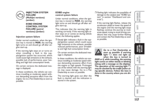 118
118 119
119 120
120 121
121 122
122 123
123 124
124 125
125 126
126 127
127 128
128 129
129 130
130 131
131 132
132 133
133 134
134 135
135 136
136 137
137 138
138 139
139 140
140 141
141 142
142 143
143 144
144 145
145 146
146 147
147 148
148 149
149 150
150 151
151 152
152 153
153 154
154 155
155 156
156 157
157 158
158 159
159 160
160 161
161 162
162 163
163 164
164 165
165 166
166 167
167 168
168 169
169 170
170 171
171 172
172 173
173 174
174 175
175 176
176 177
177 178
178 179
179 180
180 181
181 182
182 183
183 184
184 185
185 186
186 187
187 188
188 189
189 190
190 191
191 192
192 193
193 194
194 195
195 196
196 197
197 198
198 199
199 200
200 201
201 202
202 203
203 204
204 205
205 206
206 207
207 208
208 209
209