Page 189 of 367
IMPORTANT
36) The removable ball head bar can
be repaired and disassembled by
the manufacturer only.
37) The supplied plate must be
applied in a visible point on the
vehicle, close to the mounting
pipe or inside the luggage
compartment.
38) Regularly remove all dirt
deposits from the ball head bar
and from the mounting pipe to
ensure a correct system
operation. The mechanical
components must be serviced at
the specified intervals. The lock
must be treated with graphite
only.
39) Periodically lubricate the joints,
the sliding surfaces and the balls
with grease without resin or oil.
Lubrication is also a further
corrosion protection.
40) When the vehicle is cleaned with
high-pressure jets, previously
remove the ball head bar and
insert the suitable plug. The ball
head plug must never be treated
with high-pressure jets.41) Two keys are supplied together
with the removable ball tow bar.
Note down the key number on the
pawl for any following order and
keep it.
185
Page 196 of 367
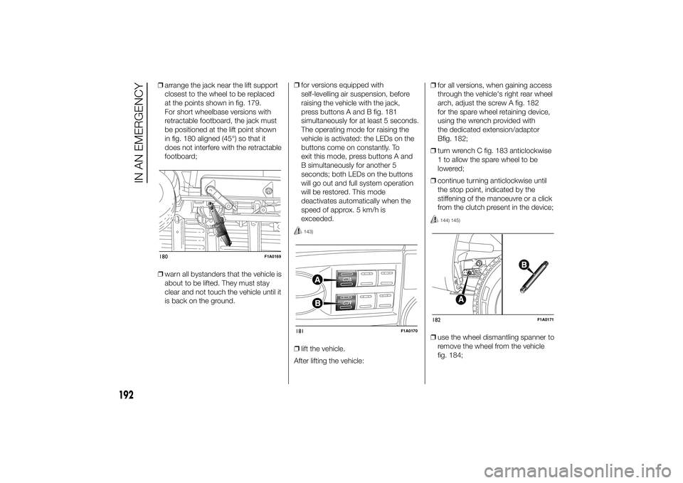
❒arrange the jack near the lift support
closest to the wheel to be replaced
at the points shown in fig. 179.
For short wheelbase versions with
retractable footboard, the jack must
be positioned at the lift point shown
in fig. 180 aligned (45°) so that it
does not interfere with the retractable
footboard;
❒warn all bystanders that the vehicle is
about to be lifted. They must stay
clear and not touch the vehicle until it
is back on the ground.❒for versions equipped with
self-levelling air suspension, before
raising the vehicle with the jack,
press buttons A and B fig. 181
simultaneously for at least 5 seconds.
The operating mode for raising the
vehicle is activated: the LEDs on the
buttons come on constantly. To
exit this mode, press buttons A and
B simultaneously for another 5
seconds; both LEDs on the buttons
will go out and full system operation
will be restored. This mode
deactivates automatically when the
speed of approx. 5 km/h is
exceeded.
143)
❒lift the vehicle.
After lifting the vehicle:❒for all versions, when gaining access
through the vehicle's right rear wheel
arch, adjust the screw A fig. 182
for the spare wheel retaining device,
using the wrench provided with
the dedicated extension/adaptor
Bfig. 182;
❒turn wrench C fig. 183 anticlockwise
1 to allow the spare wheel to be
lowered;
❒continue turning anticlockwise until
the stop point, indicated by the
stiffening of the manoeuvre or a click
from the clutch present in the device;
144) 145)
❒use the wheel dismantling spanner to
remove the wheel from the vehicle
fig. 184;
180
F1A0169
181
F1A0170
182
F1A0171
192
IN AN EMERGENCY
Page 197 of 367
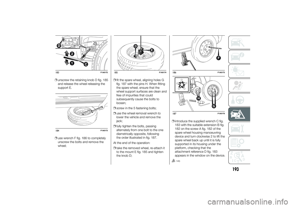
❒unscrew the retaining knob D fig. 185
and release the wheel releasing the
support E.
❒use wrench F fig. 186 to completely
unscrew the bolts and remove the
wheel;❒fit the spare wheel, aligning holes G
fig. 187 with the pins H. When fitting
the spare wheel, ensure that the
wheel support surfaces are clean and
free of impurities that could
subsequently cause the bolts to
loosen;
❒screw in the 5 fastening bolts;
❒use the wheel removal wrench to
lower the vehicle and remove the
jack;
❒fully tighten the bolts, passing
alternately from one bolt to the one
diametrically opposite, following
the order illustrated in fig. 187.
At the end of the operation:
❒take the removed wheel, re-attach it
to the mount E fig. 185 and tighten
the knob D;❒introduce the supplied wrench C fig.
183 with the suitable extension B fig.
182 on the screw A fig. 182 of the
spare wheel housing manoeuvring
device and turn clockwise 2 to lift the
spare wheel back up until it is fully
supported in its housing under the
platform, checking that the
attachment reference D fig. 183
appears in the window on the device.
146)
183
F1A0172
184
F1A0173
185
F1A0174
186
F1A0175
G
H
187
F1A0176
193
Page 198 of 367
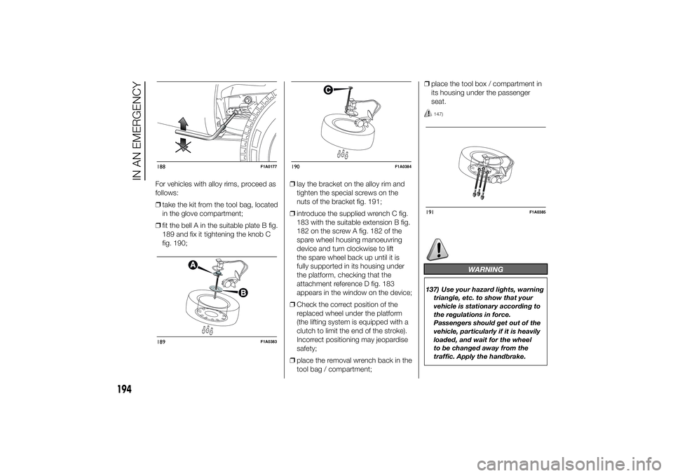
For vehicles with alloy rims, proceed as
follows:
❒take the kit from the tool bag, located
in the glove compartment;
❒fit the bell A in the suitable plate B fig.
189 and fix it tightening the knob C
fig. 190;❒lay the bracket on the alloy rim and
tighten the special screws on the
nuts of the bracket fig. 191;
❒introduce the supplied wrench C fig.
183 with the suitable extension B fig.
182 on the screw A fig. 182 of the
spare wheel housing manoeuvring
device and turn clockwise to lift
the spare wheel back up until it is
fully supported in its housing under
the platform, checking that the
attachment reference D fig. 183
appears in the window on the device;
❒Check the correct position of the
replaced wheel under the platform
(the lifting system is equipped with a
clutch to limit the end of the stroke).
Incorrect positioning may jeopardise
safety;
❒place the removal wrench back in the
tool bag / compartment;❒place the tool box / compartment in
its housing under the passenger
seat.
147)
WARNING
137) Use your hazard lights, warning
triangle, etc. to show that your
vehicle is stationary according to
the regulations in force.
Passengers should get out of the
vehicle, particularly if it is heavily
loaded, and wait for the wheel
to be changed away from the
traffic. Apply the handbrake.
188
F1A0177
189
F1A0383
190
F1A0384
191
F1A0385
194
IN AN EMERGENCY
Page 199 of 367
138) The spare wheel supplied (for
versions/markets, where
provided) is specific for your
vehicle. Therefore, it must not be
used on other models. Do not
use spare wheels of other models
on your vehicle. The wheel bolts
are specific for your vehicle: do
not use them on different models
and do not use bolts from other
models on your car.
139) Have the wheel repaired and
refitted as soon as possible. Do
not apply grease to the bolt
threads before fitting: they could
come unscrewed.
140) Use the jack only to replace
wheels on the vehicle with which
it is supplied or on other vehicles
of the same model. Never use
the jack for other purposes, such
as lifting other car models. Never
use the jack to carry out repairs
under the vehicle. Incorrect
positioning of the jack may cause
the lifted vehicle to fall. Do not
use the jack for loads higher than
those shown on the label.
141) Never tamper with the inflation
valve. Never introduce tools of any
kind between rim and tyre. Check
tyre and spare wheel pressure
regularly, referring to the values
shown in the "Technical
specifications" section.142) No tools other than the crank
provided should be used with
the spare wheel lifting device; it
should be operated by hand only.
143) On versions equipped with
self-levelling air suspension, never
introduce the head or hands in
the wheel arch: the vehicle could
raise or lower automatically
depending on possible load or
temperature changes.
144) The device should only be
operated by hand, without using
any type of tool other than the
crank provided, like pneumatic or
electrical screwers.
145) The moving components of the
jack (screw and joints) can also
cause injuries: do not touch them.
If you come into contact with
lubricating grease, clean yourself
thoroughly.146) At the end of the operation of
raising/locking the spare wheel,
after having checked the correct
positioning of the wheel under the
platform (white notch inside the
window on the device), the key
must be extracted, taking care not
to turn it in the wrong direction
to facilitate the extraction of the
key itself, to prevent the
attachment device from being
released and the wheel assembly
not being securely retained fig.
188.
147) Each time the spare wheel is
moved, check that it is correctly
positioned in its housing under
the platform. If it is not correctly
positioned, this could adversely
affect safety.
195
Page 200 of 367
FIX&GO
AUTOMATIC QUICK
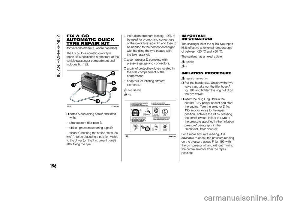
TYRE REPAIR KIT(for versions/markets, where provided)
The Fix & Go automatic quick tyre
repair kit is positioned at the front of the
vehicle passenger compartment and
includes fig. 192:
❒bottle A containing sealer and fitted
with:
– a transparent filler pipe B;
– a black pressure restoring pipe E;
– sticker C bearing the notice “max. 80
km/h”, to be placed in a position visible
to the driver (on the instrument panel)
after fixing the tyre;❒instruction brochure (see fig. 193), to
be used for prompt and correct use
of the quick tyre repair kit and then to
be handed to the personnel charged
with handling the tyre treated with
the tyre repair kit;
❒a compressor D complete with
pressure gauge and connectors;
❒a pair of protective gloves located in
the side compartment of the
compressor;
❒adaptors for inflating different
elements.
148) 149) 150)43)
IMPORTANT
INFORMATION:
The sealing fluid of the quick tyre repair
kit is effective at external temperatures
of between -20 °C and +50 °C.
The sealant has an expiry date.
151) 152)2)
INFLATION PROCEDURE
153) 154) 155) 156) 157)
❒Pull the handbrake. Unscrew the tyre
valve cap, take out the filler hose A
fig. 194 and tighten the ring nut B on
the tyre valve;
❒insert the plug E fig. 196 in the
nearest 12 V power socket and start
the engine. Turn the selector D fig.
195 anticlockwise to the repair
position. Activate the kit by pressing
the on/off switch. Inflate the tyre to
the pressure specified in the "Inflation
pressure" paragraph, in the
"Technical Data" chapter;
For a more accurate reading, it is
advisable to check the pressure reading
on the pressure gauge F fig. 195 with
the compressor off and without moving
the centre selector from the repair
position;
192
F1A0180
193
F1A0181
196
IN AN EMERGENCY
Page 202 of 367
FOR CHECKING AND
RESTORING PRESSURE
ONLY
The compressor can also be used
solely for restoring pressure.
❒Pull the handbrake.
❒Undo the cap for the tyre valve,
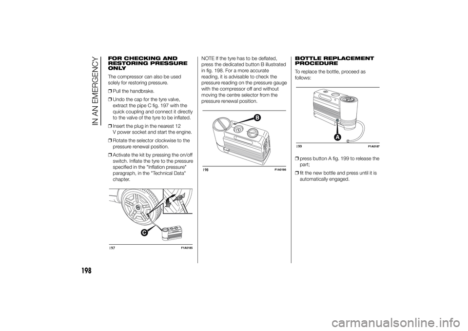
extract the pipe C fig. 197 with the
quick coupling and connect it directly
to the valve of the tyre to be inflated.
❒Insert the plug in the nearest 12
V power socket and start the engine.
❒Rotate the selector clockwise to the
pressure renewal position.
❒Activate the kit by pressing the on/off
switch. Inflate the tyre to the pressure
specified in the "Inflation pressure"
paragraph, in the "Technical Data"
chapter.NOTE If the tyre has to be deflated,
press the dedicated button B illustrated
in fig. 198. For a more accurate
reading, it is advisable to check the
pressure reading on the pressure gauge
with the compressor off and without
moving the centre selector from the
pressure renewal position.BOTTLE REPLACEMENT
PROCEDURE
To replace the bottle, proceed as
follows:
❒press button A fig. 199 to release the
part;
❒fit the new bottle and press until it is
automatically engaged.197
F1A0185
198
F1A0186
199
F1A0187
198
IN AN EMERGENCY
Page 206 of 367
TYPES OF BULBSVarious types of bulbs are fitted to your car:All-glass bulbs:(type A) press-fitted. Pull to remove.Bayonet type bulbs:(type B) to remove them press the bulb
and turn it anticlockwise.
Tubular bulbs:(type C) release them from their contacts to
remove.
Halogen bulbs:(type D) to remove the bulb, release it and
extract it from its housing.
Halogen bulbs:(type E) to remove the bulb, release it and
extract it from its housing.
202
IN AN EMERGENCY