Page 58 of 476

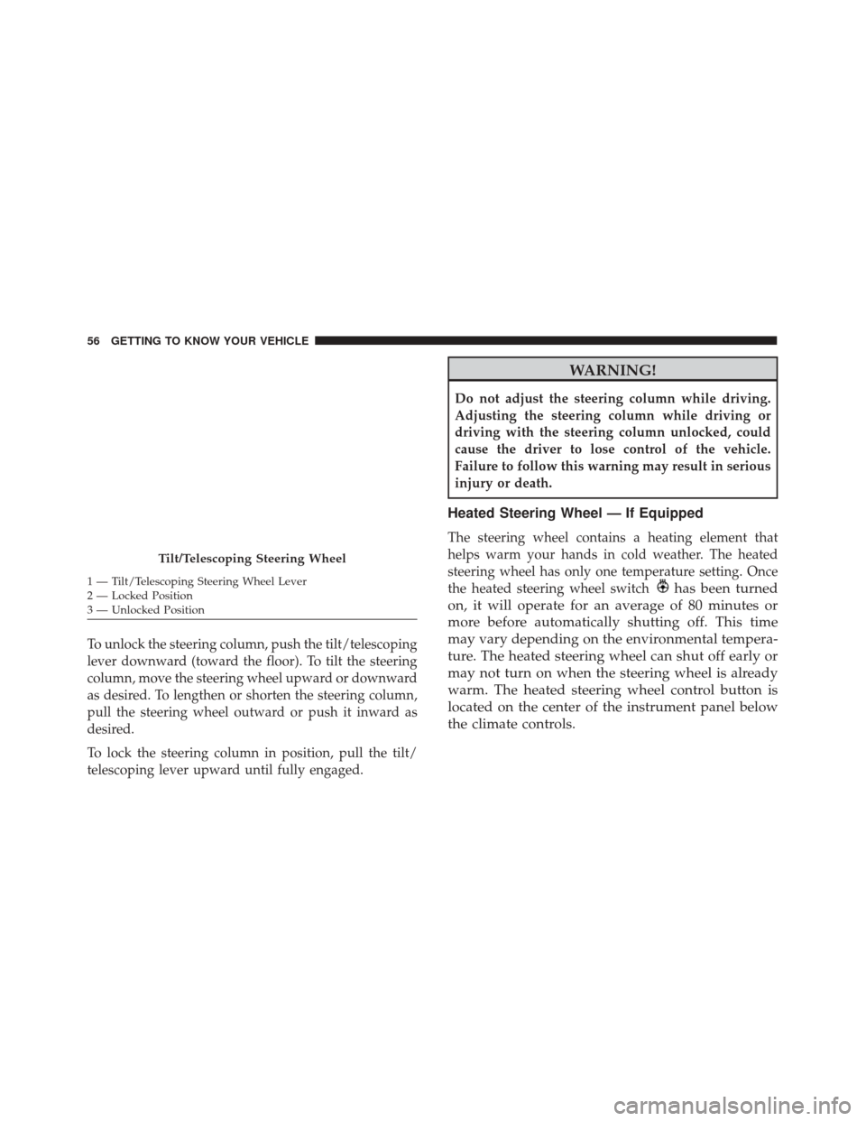
To unlock the steering column, push the tilt/telescoping
lever downward (toward the floor). To tilt the steering
column, move the steering wheel upward or downward
as desired. To lengthen or shorten the steering column,
pull the steering wheel outward or push it inward as
desired.
To lock the steering column in position, pull the tilt/
telescoping lever upward until fully engaged.
WARNING!
Do not adjust the steering column while driving.
Adjusting the steering column while driving or
driving with the steering column unlocked, could
cause the driver to lose control of the vehicle.
Failure to follow this warning may result in serious
injury or death.
Heated Steering Wheel — If Equipped
The steering wheel contains a heating element that
helps warm your hands in cold weather. The heated
steering wheel has only one temperature setting. Once
the heated steering wheel switch
has been turned
on, it will operate for an average of 80 minutes or
more before automatically shutting off. This time
may vary depending on the environmental tempera-
ture. The heated steering wheel can shut off early or
may not turn on when the steering wheel is already
warm. The heated steering wheel control button is
located on the center of the instrument panel below
the climate controls.
Tilt/Telescoping Steering Wheel
1 — Tilt/Telescoping Steering Wheel Lever
2 — Locked Position
3 — Unlocked Position 56 GETTING TO KNOW YOUR VEHICLE
Page 62 of 476

vehicle is in any forward gear or REVERSE and enters
stand-by mode when the vehicle is in PARK.
The BSM detection zone covers approximately one lane
width on both sides of the vehicle, 10 ft (3 m). The zone
length starts at the outside mirror and extends approxi-
mately 20 ft (6 m) beyond the rear bumper of the
vehicle. The BSM system monitors the detection zones
on both sides of the vehicle when the vehicle speed
reaches approximately 6 mph (10 km/h) or higher and
will alert the driver of vehicles in these areas.
NOTE:
•The BSM system does NOT alert the driver about
rapidly approaching vehicles that are outside the
detection zones.
• If a trailer is connected to the vehicle, it is necessary
to deactivate BSM system manually by settings menu
to avoid a miss-detection. Refer to “Uconnect Set-
tings” in “Multimedia” for further information.
The area on the rear fascia where the radar sensors are
located must remain free of snow, ice, and dirt/road
contamination so that the BSM system can function properly. Do not block the radar sensors located on the
rear fascia with foreign objects (bumper stickers, bicycle
racks, etc.).
The BSM system notifies the driver of objects in the
detection zones by illuminating the BSM warning light
located in the outside mirrors in addition to sounding
an audible (chime) alert and reducing the radio volume.
Refer to “Modes Of Operation” in this section for
further information.
Rear Sensor Locations
60 GETTING TO KNOW YOUR VEHICLE
Page 66 of 476

Rear Cross Path (RCP)
The Rear Cross Path (RCP) feature is intended to aid the
driver when backing out of parking spaces where their
vision of oncoming vehicles may be blocked. Proceed
slowly and cautiously out of the parking space until the
rear end of the vehicle is exposed. The RCP system will
then have a clear view of the cross traffic and if an
oncoming vehicle is detected, alert the driver.
RCP monitors the rear detection zones on both sides of
the vehicle, for objects that are moving toward the side
of the vehicle with a minimum speed of approximately1 mph (2 km/h), to objects moving a maximum of
approximately 22 mph (35 km/h), such as in parking lot
situations.
NOTE:
In a parking lot situation, oncoming vehicles
can be obscured by vehicles parked on either side. If the
sensors are blocked by other structures or vehicles, the
system will not be able to alert the driver.
When RCP is on and the vehicle is in REVERSE, the
driver is alerted using both the visual and audible
alarms, including reducing the radio volume.
WARNING!
RCP is not a back up aid system. It is intended to be
used to help a driver detect an oncoming vehicle in
a parking lot situation. Drivers must be careful
when backing up, even when using RCP. Always
check carefully behind your vehicle, look behind
you, and be sure to check for pedestrians, animals,
other vehicles, obstructions, and blind spots before
backing up. Failure to do so can result in serious
injury or death.
RCP Detection Zones
64 GETTING TO KNOW YOUR VEHICLE
Page 73 of 476

NOTE:
•Before exiting the vehicle, make sure that the interior
lights are turned off. This will prevent the battery
from discharging once the doors are closed.
• If a light is left on it will automatically be turned off
after approximately 15 minutes after the ignition is in
STOP mode.
Dome Light Timing
The Dome Light will automatically illuminate when the
doors are unlocked, the doors are opened or after the
doors are closed.
Timing Entering The Vehicle
The dome lights illuminate in the following ways:
• When the doors are unlocked, the dome light will
illuminate for approximately 27 seconds.
• When one of the doors is opened, the dome light will
illuminate for approximately three minutes.
• When the doors are closed, the dome light will
automatically shut off after approximately 27 sec-
onds. NOTE:
The timing stops once the ignition is placed in
the RUN or START mode.
The dome light will turn off under any of the following
conditions:
• The dome light is disabled when the ignition is
placed in the RUN or START mode.
• The dome lights will turn off automatically when the
doors are locked.
• The dome lights will automatically turn off after
approximately fifteen minutes of inactivity to pre-
serve the battery.
Timing Exiting The Vehicle
The dome light will illuminate under the following
conditions when the ignition is turned to the STOP
mode:
• The dome light will illuminate for 27 seconds after
the key is removed from the vehicle.
• The opening of one of the doors (approximately three
minutes).
• After closing a door (approximately 27 seconds).
4
GETTING TO KNOW YOUR VEHICLE 71
Page 74 of 476
The dome light timing is disabled when the doors are
locked.
Illuminated Vanity Mirrors — If Equipped
An illuminated vanity mirror is located on each sun
visor. To use the mirror, rotate the sun visor down and
swing the mirror cover upward. The lights will turn on
automatically. Closing the mirror cover will turn the
light off.
Lower Glove Compartment Light
An interior light is located is the lower glove compart-
ment.
This light automatically turn on/off when the glove
compartment is opened and closed, regardless of the
position of the ignition.
NOTE:In order to preserve the life of the battery, the
light will turn off after 15 minutes.
Vanity Mirror Light
Lower Glove Compartment Light
72 GETTING TO KNOW YOUR VEHICLE
Page 84 of 476

Manual Climate Control Descriptions
IconDescription
MAX A/C Setting
MAX A/C sets the system for maximum cooling performance. Rotate the temperature con-
trol adjust knob counterclockwise to the MAX A/C setting. In MAX A/C, the blower speed
and mode position can be adjusted to desired user settings.
A/C Button
Push this button to engage the Air Conditioning. A light will illuminate when the Air Con-
ditioning system is engaged.
Recirculation Button
Push this control button to change the system between recirculation mode and outside air
mode. Recirculation can be used when outside conditions such as smoke, odors, dust, or
high humidity are present.
NOTE:
•Continuous use of the Recirculation mode may make the inside air stuffy and window
fogging may occur. Extended use of this mode is not recommended.
•The use of the Recirculation mode in cold or damp weather could cause windows to fog
on the inside, because of moisture buildup inside the vehicle. Select the outside air posi-
tion for maximum defogging.
•Recirculation can be used in all modes except for Defrost.
•The A/C can be deselected manually without disturbing the mode control selection.
82 GETTING TO KNOW YOUR VEHICLE
Page 85 of 476

IconDescription
Front Defrost Mode
Air is directed through the windshield and side window demister outlets. Use this mode
with maximum blower and temperature settings for best windshield and side window de-
frosting.
NOTE:The air conditioning compressor operates in Mix or Defrost, even if the Air Condi-
tioning (A/C) button is not pushed. This dehumidifies the air to help dry the windshield.
To improve fuel economy, use these modes only when required.
Rear Defrost Button
Push and release the Rear Defrost Control button to turn on the rear window defroster and
the heated outside mirrors (if equipped). An indicator will illuminate when the rear win-
dow defroster is on. The rear window defroster automatically turns off after 20 minutes.
Temperature Control
Rotate this control to regulate the temperature of the air inside the passenger compartment.
Rotating the dial counterclockwise into the blue area of the scale indicates cooler tempera-
tures, while rotating clockwise into the red area indicates warmer temperatures. Rotating
the Temperature Control all the way counterclockwise results in turning on the MAX A/C
feature.
Blower Control
Rotate this control to regulate the amount of air forced through the ventilation system in
any mode. The blower speed increases as you move the control clockwise from the “0”
(OFF) position.
4
GETTING TO KNOW YOUR VEHICLE 83
Page 89 of 476

Automatic Climate Control Descriptions
IconDescription
MAX A/C Setting
MAX A/C sets the system for maximum cooling performance. Rotate the driver tempera-
ture control adjust knob counterclockwise for MAX A/C. Both driver and passenger tem-
perature displays will show MAX A/C LO. In MAX A/C, the blower speed and mode po-
sition can be adjusted to desired user settings. Pressing other settings will cause the MAX
A/C operation to switch to the selected setting and MAX A/C to exit.
A/C Button
Push the A/C Control Button to change the current setting. The indicator illuminates when
the A/C is ON. Pushing the AUTO control button will cause the A/C operation to change
to AUTO mode and the A/C indicator will turn off.
SYNC Button
Push the Sync button to toggle the Sync feature ON/OFF. The Sync indicator will illumi-
nate when this feature is enabled. Sync is used to synchronize the passenger temperature
setting with the driver temperature setting. Changing the passenger temperature setting
while in Sync mode will automatically exit this feature and return to the separate manage-
ment of air temperatures in the two zones.
4
GETTING TO KNOW YOUR VEHICLE 87