Page 177 of 331
175
E3_en_Chap09_info_pratiques_ed01-2014
A. "Sealant" or "Air" position selector.
B. On "I" / off "O" switch.
C.
D
eflation button.
D.
P
ressure gauge (in bar and p.s.i.).
E.
C
ompartment housing:
-
a c
able with adaptor for 12 V socket,
-
v
arious inflation adaptors for
accessories, such as balls, bicycle
tyres...
Description of the kit
The speed limit sticker I must be affixed
to the vehicle's steering wheel to remind
you that a wheel is in temporary use.
Do not exceed a speed of 50 mph
(80 km/h) when driving with a tyre
repaired using this type of kit.
F.
S
ealant cartridge.
G.
W
hite pipe with cap for repair.
H.
B
lack pipe for inflation.
I.
Spe
ed limit sticker.
The tyre inflation pressures are given on this
label.
9
Practical information
Page 178 of 331
176
E3_en_Chap09_info_pratiques_ed01-2014
1. Sealing
Repair procedure
Avoid removing any foreign bodies
which have penetrated into the tyre.F
U
ncoil the white pipe G fully.
F
U
nscrew the cap from the white pipe.
F
C
onnect the white pipe to the valve of the
tyre to be repaired.
F
S
witch off the ignition.
F
T
urn the selector A to the
"sealant" position.
F
C
heck that the switch B is in
position "O" . F
C
onnect the compressor's electric plug to
the vehicle's 12 V socket.
F
S
tart the vehicle and leave the engine
running.
Take care, this product is harmful (e.g.
ethylene-glycol, colophony...) if swallowed
and causes irritation to the eyes.
Keep this product out of the reach of
children. Do not start the compressor before
connecting the white pipe to the tyre
valve: the sealant product would be
expelled through the pipe.
Practical information
Page 179 of 331

177
E3_en_Chap09_info_pratiques_ed01-2014
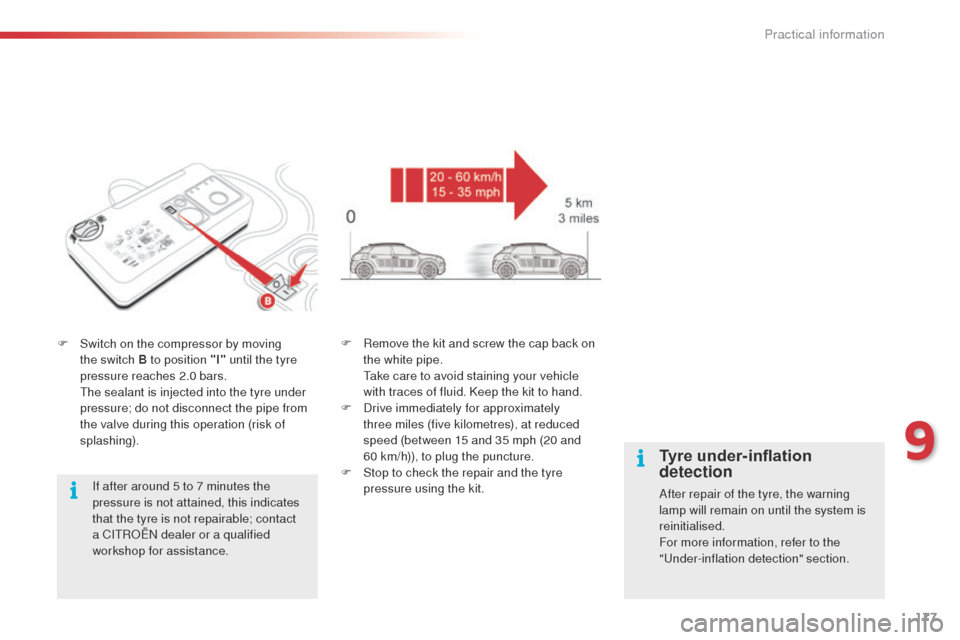
F Switch on the compressor by moving the switch B to position "I" until the tyre
pressure reaches 2.0 bars.
T
he sealant is injected into the tyre under
pressure; do not disconnect the pipe from
the valve during this operation (risk of
splashing).
If after around 5 to 7 minutes the
pressure is not attained, this indicates
that the tyre is not repairable; contact
a CITROËN dealer or a qualified
workshop for assistance. F
R emove the kit and screw the cap back on
the white pipe.
T
ake care to avoid staining your vehicle
with traces of fluid. Keep the kit to hand.
F
D
rive immediately for approximately
three miles (five kilometres), at reduced
speed (between 15 and 35 mph (20 and
60
km/h)), to plug the puncture.
F
S
top to check the repair and the tyre
pressure using the kit.
Tyre under-inflation
detection
After repair of the tyre, the warning
lamp will remain on until the system is
reinitialised.
For more information, refer to the
"Under-inflation detection" section.
9
Practical information
Page 180 of 331

178
E3_en_Chap09_info_pratiques_ed01-2014
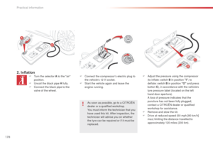
2. InflationF Turn the selector A to the "air" position.
F
U
ncoil the black pipe H fully.
F
C
onnect the black pipe to the
valve of the wheel. F
C onnect the compressor's electric plug to
the vehicle's 12 V socket.
F
S
tart the vehicle again and leave the
engine running.
As soon as possible, go to a CITROËN
dealer or a qualified workshop.
You must inform the technician that you
have used this kit. After inspection, the
technician will advise you on whether
the tyre can be repaired or if it must be
replaced. F
A djust the pressure using the compressor
(to inflate: switch B in position "I" ; to
deflate: switch B
in position "O" and press
button C ), in accordance with the vehicle's
tyre pressure label (located on the left
hand door aperture).
A l
oss of pressure indicates that the
puncture has not been fully plugged;
contact a CITROËN dealer or qualified
workshop for assistance.
F
R
emove and stow the kit.
F
D
rive at reduced speed (50 mph [80 km/h]
max) limiting the distance travelled to
approximately 120 miles (200 km).
Practical information
Page 181 of 331
179
E3_en_Chap09_info_pratiques_ed01-2014
Removing the cartridge
F Stow the black pipe.
F D etach the angled base from the white
pipe.
F
S
upport the compressor vertically.
F
U
nscrew the cartridge from the bottom. Beware of discharges of fluid.
The expiry date of the fluid is indicated
on the cartridge.
The sealant cartridge is designed for
single use; even if only partly used, it
must be replaced.
After use, do not discard the cartridge
into the environment, take it to an
authorised waste disposal site or a
CITROËN dealer.
Do not forget to obtain a new sealant
cartridge, available from CITROËN
dealers or from a qualified workshop.
9
Practical information
Page 182 of 331

180
E3_en_Chap09_info_pratiques_ed01-2014
Checking tyre pressures /
inflating accessories
You can also use the compressor, without
injecting any product, to:
-
c
heck or adjust the pressure of your tyres,
-
i
nflate other accessories (balls, bicycle
tyres...).
F
T
urn the selector A to the "Air"
position.
F
U
ncoil the black pipe H fully. F
C onnect the compressor's electrical
connector to the vehicle's 12 V socket.
F
S
tart the vehicle and let the engine run.
F
A
djust the pressure using the compressor
(to inflate: switch B in position "I" ; to
deflate: switch B in position "O" and press
button C ), according to the vehicle's tyre
pressure label or the accessory's pressure
label.
F
R
emove the kit then stow it.Should the pressure of one or more
tyres be adjusted, it is necessary to
reinitialise the under-inflation detection
system.
Refer to the "Under-inflation detection"
section.
F
C
onnect the black pipe to the valve of the
wheel or accessory.
I
f necessary, fit one of the adaptors
supplied with the kit first.
Practical information
Page 183 of 331
181
E3_en_Chap09_info_pratiques_ed01-2014
Changing a wheel
The tools are installed in the boot under the
floor, or may be located, depending on version,
under the front passenger seat.
Access to the tools
List of tools
All of these tools are specific to your
vehicle and can vary according to the level
of equipment. Do not use them for other
purposes.
1.
Wheelbrace.
F
or removing the wheel trim and the wheel
bolts.
2.
J
ack with integral handle.
F
or raising the vehicle.
3.
B
olt cover removal tool.
F
or removing the bolt covers on alloy
wheels or the central wheel cap (depending
on version).
4.
T
owing eye.
Refer to the "Towing" section.
Procedure for changing a wheel for the spare wheel using the tools provided with the vehicle.
Wheel with trim
When refitting the wheel
, refit the trim
starting by placing its notch facing the valve
and press around its edge with the palm of
your hand.
9
Practical information
Page 184 of 331
182
E3_en_Chap09_info_pratiques_ed01-2014
F Unclip the tool storage box by pulling on it. The spare wheel is installed in the boot under
t h e f l o o r.
Spare wheel (depending on version)
Taking out the wheel
F Unscrew the yellow central bolt.
F R aise the spare wheel towards you from
the rear.
F
T
ake the wheel out of the boot.
Putting the wheel back in place
F Put the wheel back in its housing.
F U nscrew the yellow central bolt by a few
turns then put it in place in the centre of the
wheel.
F
T
ighten fully until the central bolt clicks to
retain the wheel correctly.
F
C
lip the tool storage box back into place.
Practical information