2013 YAMAHA YZ125LC checking oil
[x] Cancel search: checking oilPage 91 of 168
4-29
YPVS GOVERNOR
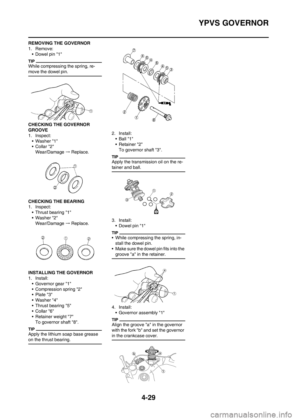
REMOVING THE GOVERNOR
1. Remove:
• Dowel pin "1"
While compressing the spring, re-
move the dowel pin.
CHECKING THE GOVERNOR
GROOVE
1. Inspect:
• Washer "1"
•Collar "2"
Wear/Damage → Replace.
CHECKING THE BEARING
1. Inspect:
• Thrust bearing "1"
• Washer "2"
Wear/Damage → Replace.
INSTALLING THE GOVERNOR
1. Install:
• Governor gear "1"
• Compression spring "2"
• Plate "3"
• Washer "4"
• Thrust bearing "5"
•Collar "6"
• Retainer weight "7"
To governor shaft "8".
Apply the lithium soap base grease
on the thrust bearing.
2. Install:
• Ball "1"
• Retainer "2"
To governor shaft "3".
Apply the transmission oil on the re-
tainer and ball.
3. Install:
• Dowel pin "1"
• While compressing the spring, in-
stall the dowel pin.
• Make sure the dowel pin fits into the
groove "a" in the retainer.
4. Install:
• Governor assembly "1"
Align the groove "a" in the governor
with the fork "b" and set the governor
in the crankcase cover.
Page 93 of 168
4-31
WATER PUMP
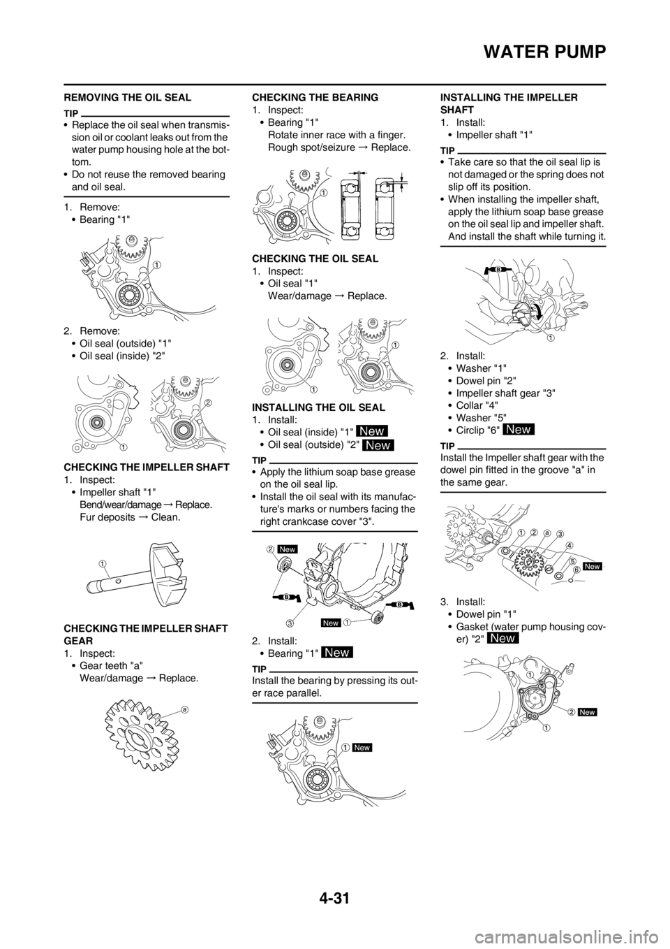
REMOVING THE OIL SEAL
• Replace the oil seal when transmis-
sion oil or coolant leaks out from the
water pump housing hole at the bot-
tom.
• Do not reuse the removed bearing
and oil seal.
1. Remove:
• Bearing "1"
2. Remove:
• Oil seal (outside) "1"
• Oil seal (inside) "2"
CHECKING THE IMPELLER SHAFT
1. Inspect:
• Impeller shaft "1"
Bend/wear/damage → R e p l a c e .
Fur deposits → Clean.
CHECKING THE IMPELLER SHAFT
GEAR
1. Inspect:
• Gear teeth "a"
Wear/damage →Replace. CHECKING THE BEARING
1. Inspect:
•Bearing "1"
Rotate inner race with a finger.
Rough spot/seizure → Replace.
CHECKING THE OIL SEAL
1. Inspect:
• Oil seal "1"
Wear/damage → Replace.
INSTALLING THE OIL SEAL
1. Install:
• Oil seal (inside) "1"
• Oil seal (outside) "2"
• Apply the lithium soap base grease
on the oil seal lip.
• Install the oil seal with its manufac-
ture's marks or numbers facing the
right crankcase cover "3".
2. Install:
• Bearing "1"
Install the bearing by pressing its out-
er race parallel.
INSTALLING THE IMPELLER
SHAFT
1. Install:
• Impeller shaft "1"
• Take care so that the oil seal lip is
not damaged or the spring does not
slip off its position.
• When installing the impeller shaft,
apply the lithium soap base grease
on the oil seal lip and impeller shaft.
And install the shaft while turning it.
2. Install:
• Washer "1"
• Dowel pin "2"
• Impeller shaft gear "3"
•Collar "4"
• Washer "5"
• Circlip "6"
Install the Impeller shaft gear with the
dowel pin fitted in the groove "a" in
the same gear.
3. Install:
• Dowel pin "1"
• Gasket (water pump housing cov-
er) "2"
Page 103 of 168

4-41
CRANKCASE AND CRANKSHAFT
REMOVING THE SEGMENT
1. Remove:
• Bolt (segment) "1"
• Segment "2"
Turn the segment counterclockwise
until it stops and loosen the bolt.
If the segment gets an impact, it
may be damaged. Take care not to
give an impact to the segment
when removing the bolt.
DISASSEMBLING THE
CRANKCASE
1. Remove:
• Crankcase (right) "1"
Use the flywheel puller "2".
• Make appropriate bolts "3" as
shown available by yourself and at-
tach the tool with them.
• Fully tighten the tool holding bolts,
but make sure the tool body is par-
allel with the case. If necessary,
one screw may be backed out
slightly to level tool body.
• As pressure is applied, alternately
tap on the engine mounting boss
and transmission shafts.
Use soft hammer to tap on the
case half. Tap only on reinforced
portions of case. Do not tap on
gasket mating surface. Work slow-
ly and carefully. Make sure the
case halves separate evenly. If one
end "hangs up", take pressure off
the push screw, realign, and start
over. If the cases do not separate,
check for a remaining case bolt or
fitting. Do not force.
REMOVING THE CRANKSHAFT
1. Remove:
• Crankshaft "1"
Use the crankcase separating
tool "2".
Make appropriate bolts "3" as shown
available by yourself and attach the
tool with them.
Do not use a hammer to drive out
the crankshaft.
REMOVING THE CRANKCASE
BEARING
1. Remove:
•Bearing "1"
• Remove the bearing from the
crankcase by pressing its inner race
as shown in "A".
• If the bearing is removed together
with the crankshaft, remove the
bearing using a general bearing
puller "2" as shown in "B".
• Do not use the removed bearing.
CHECKING THE CRANKCASE
1. Inspect:
• Contacting surface "a"
Scratches → Replace.
• Engine mounting boss "b", crank-
case
Cracks/damage → Replace.
2. Inspect:
• Bearing "1"
Rotate inner race with a finger.
Rough spot/seizure → R e p l a c e .
3. Inspect:
• Oil seal "1"
Damage →Replace.
CHECKING THE CRANKSHAFT
1. Measure:
• Runout limit "a"
• Small end free play limit "b"
• Connecting rod big end side
clearance "c"
• Crank width "d"
Out of specification → R e p l a c e .
Use the dial gauge and a thick-
ness gauge. Flywheel puller:
YU-33270-B/90890-
01362
Crankcase separating
tool:
YU-1135-A/90890-
01135
Dial gauge and stand:
YU-3097/90890-01252
Page 105 of 168
4-43
CRANKCASE AND CRANKSHAFT
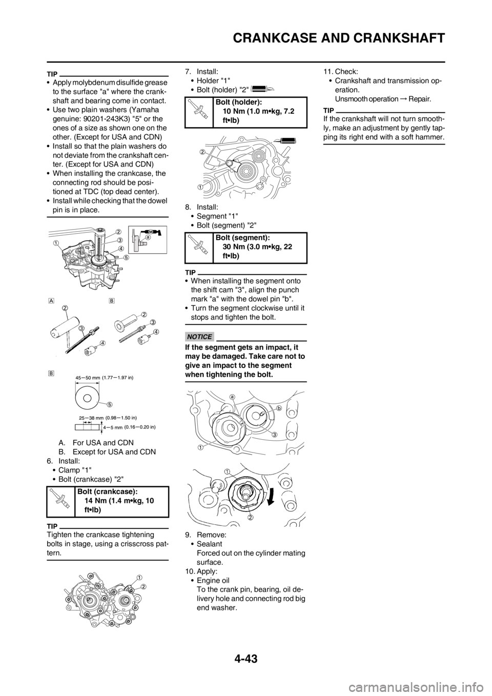
• Apply molybdenum disulfide grease
to the surface "a" where the crank-
shaft and bearing come in contact.
• Use two plain washers (Yamaha
genuine: 90201-243K3) "5" or the
ones of a size as shown one on the
other. (Except for USA and CDN)
• Install so that the plain washers do
not deviate from the crankshaft cen-
ter. (Except for USA and CDN)
• When installing the crankcase, the
connecting rod should be posi-
tioned at TDC (top dead center).
• Install while checking that the dowel
pin is in place.
A. For USA and CDN
B. Except for USA and CDN
6. Install:
• Clamp "1"
• Bolt (crankcase) "2"
Tighten the crankcase tightening
bolts in stage, using a crisscross pat-
tern.
7. Install:
• Holder "1"
• Bolt (holder) "2"
8. Install:
• Segment "1"
• Bolt (segment) "2"
• When installing the segment onto
the shift cam "3", align the punch
mark "a" with the dowel pin "b".
• Turn the segment clockwise until it
stops and tighten the bolt.
If the segment gets an impact, it
may be damaged. Take care not to
give an impact to the segment
when tightening the bolt.
9. Remove:
• Sealant
Forced out on the cylinder mating
surface.
10. Apply:
• Engine oil
To the crank pin, bearing, oil de-
livery hole and connecting rod big
end washer.11. Check:
• Crankshaft and transmission op-
eration.
Unsmooth operation → R e p a i r .
If the crankshaft will not turn smooth-
ly, make an adjustment by gently tap-
ping its right end with a soft hammer.
Bolt (crankcase):
14 Nm (1.4 m•kg, 10
ft•lb)
Bolt (holder):
10 Nm (1.0 m•kg, 7.2
ft•lb)
Bolt (segment):
30 Nm (3.0 m•kg, 22
ft•lb)
Page 107 of 168
4-45
TRANSMISSION, SHIFT CAM AND SHIFT FORK
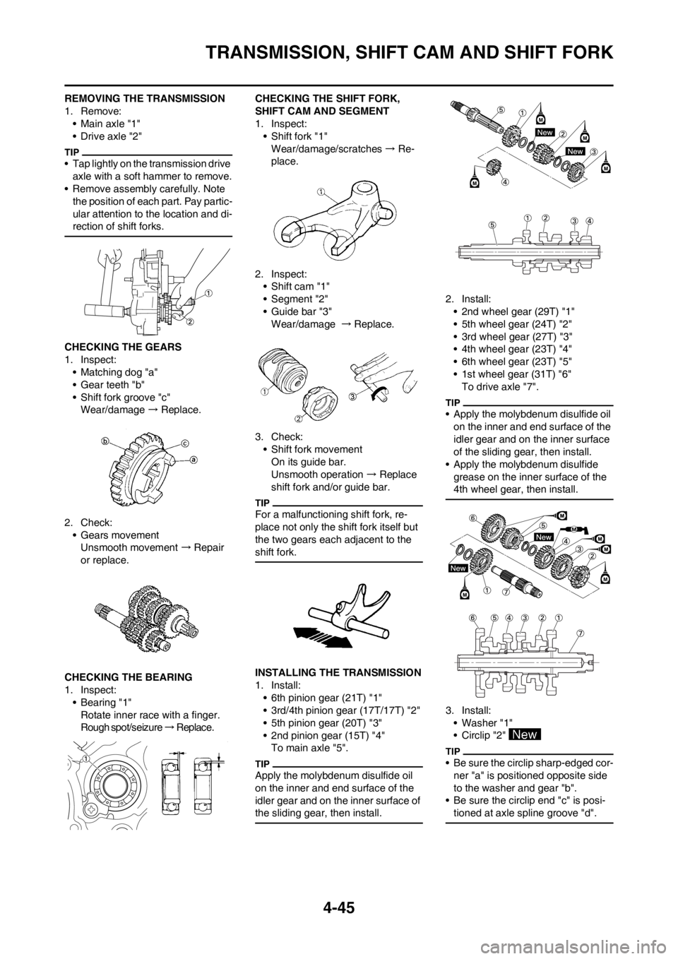
REMOVING THE TRANSMISSION
1. Remove:
• Main axle "1"
• Drive axle "2"
• Tap lightly on the transmission drive
axle with a soft hammer to remove.
• Remove assembly carefully. Note
the position of each part. Pay partic-
ular attention to the location and di-
rection of shift forks.
CHECKING THE GEARS
1. Inspect:
• Matching dog "a"
• Gear teeth "b"
• Shift fork groove "c"
Wear/damage → Replace.
2. Check:
• Gears movement
Unsmooth movement → Repair
or replace.
CHECKING THE BEARING
1. Inspect:
• Bearing "1"
Rotate inner race with a finger.
Rough spot/seizure → R e p l a c e . CHECKING THE SHIFT FORK,
SHIFT CAM AND SEGMENT
1. Inspect:
• Shift fork "1"
Wear/damage/scratches → Re-
place.
2. Inspect:
• Shift cam "1"
• Segment "2"
• Guide bar "3"
Wear/damage →Replace.
3. Check:
• Shift fork movement
On its guide bar.
Unsmooth operation → Replace
shift fork and/or guide bar.
For a malfunctioning shift fork, re-
place not only the shift fork itself but
the two gears each adjacent to the
shift fork.
INSTALLING THE TRANSMISSION
1. Install:
• 6th pinion gear (21T) "1"
• 3rd/4th pinion gear (17T/17T) "2"
• 5th pinion gear (20T) "3"
• 2nd pinion gear (15T) "4"
To main axle "5".
Apply the molybdenum disulfide oil
on the inner and end surface of the
idler gear and on the inner surface of
the sliding gear, then install.
2. Install:
• 2nd wheel gear (29T) "1"
• 5th wheel gear (24T) "2"
• 3rd wheel gear (27T) "3"
• 4th wheel gear (23T) "4"
• 6th wheel gear (23T) "5"
• 1st wheel gear (31T) "6"
To drive axle "7".
• Apply the molybdenum disulfide oil
on the inner and end surface of the
idler gear and on the inner surface
of the sliding gear, then install.
• Apply the molybdenum disulfide
grease on the inner surface of the
4th wheel gear, then install.
3. Install:
• Washer "1"
• Circlip "2"
• Be sure the circlip sharp-edged cor-
ner "a" is positioned opposite side
to the washer and gear "b".
• Be sure the circlip end "c" is posi-
tioned at axle spline groove "d".
Page 111 of 168
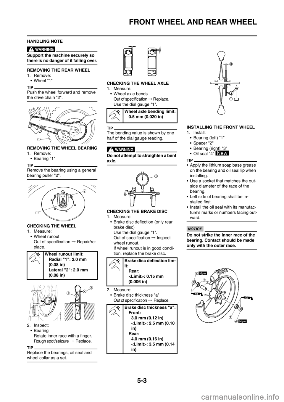
5-3
FRONT WHEEL AND REAR WHEEL
HANDLING NOTE
Support the machine securely so
there is no danger of it falling over.
REMOVING THE REAR WHEEL
1. Remove:
• Wheel "1"
Push the wheel forward and remove
the drive chain "2".
REMOVING THE WHEEL BEARING
1. Remove:
• Bearing "1"
Remove the bearing using a general
bearing puller "2".
CHECKING THE WHEEL
1. Measure:
• Wheel runout
Out of specification → Repair/re-
place.
2. Inspect:
• Bearing
Rotate inner race with a finger.
Rough spot/seizure → R e p l a c e .
Replace the bearings, oil seal and
wheel collar as a set.
CHECKING THE WHEEL AXLE
1. Measure:
• Wheel axle bends
Out of specification → R e p l a c e .
Use the dial gauge "1".
The bending value is shown by one
half of the dial gauge reading.
Do not attempt to straighten a bent
axle.
CHECKING THE BRAKE DISC
1. Measure:
• Brake disc deflection (only rear
brake disc)
Use the dial gauge "1".
Out of specification → Inspect
wheel runout.
If wheel runout is in good condi-
tion, replace the brake disc.
2. Measure:
• Brake disc thickness "a"
Out of specification → R e p l a c e . INSTALLING THE FRONT WHEEL
1. Install:
• Bearing (left) "1"
• Spacer "2"
• Bearing (right) "3"
• Oil seal "4"
• Apply the lithium soap base grease
on the bearing and oil seal lip when
installing.
• Use a socket that matches the out-
side diameter of the race of the
bearing.
• Left side of bearing shall be in-
stalled first.
• Install the oil seal with its manufac-
ture's marks or numbers facing out-
ward.
Do not strike the inner race of the
bearing. Contact should be made
only with the outer race.
Wheel runout limit:
Radial "1": 2.0 mm
(0.08 in)
Lateral "2": 2.0 mm
(0.08 in)
Wheel axle bending limit:
0.5 mm (0.020 in)
Brake disc deflection lim-
it:
Rear:
(0.006 in)
Brake disc thickness "a":
Front:
3.0 mm (0.12 in)
in)
Rear:
4.0 mm (0.16 in)
in)
Page 122 of 168
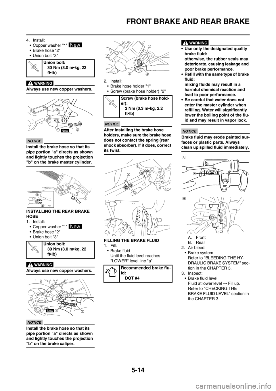
5-14
FRONT BRAKE AND REAR BRAKE
4. Install:
• Copper washer "1"
• Brake hose "2"
• Union bolt "3"
Always use new copper washers.
Install the brake hose so that its
pipe portion "a" directs as shown
and lightly touches the projection
"b" on the brake master cylinder.
INSTALLING THE REAR BRAKE
HOSE
1. Install:
• Copper washer "1"
• Brake hose "2"
• Union bolt "3"
Always use new copper washers.
Install the brake hose so that its
pipe portion "a" directs as shown
and lightly touches the projection
"b" on the brake caliper.
2. Install:
• Brake hose holder "1"
• Screw (brake hose holder) "2"
After installing the brake hose
holders, make sure the brake hose
does not contact the spring (rear
shock absorber). If it does, correct
its twist.
FILLING THE BRAKE FLUID
1. Fill:
•Brake fluid
Until the fluid level reaches
"LOWER" level line "a".
• Use only the designated quality
brake fluid:
otherwise, the rubber seals may
deteriorate, causing leakage and
poor brake performance.
• Refill with the same type of brake
fluid;
mixing fluids may result in a
harmful chemical reaction and
lead to poor performance.
• Be careful that water does not
enter the master cylinder when
refilling. Water will significantly
lower the boiling point of the flu-
id and may result in vapor lock.
Brake fluid may erode painted sur-
faces or plastic parts. Always
clean up spilled fluid immediately.
A. Front
B. Rear
2. Air bleed:
• Brake system
Refer to "BLEEDING THE HY-
DRAULIC BRAKE SYSTEM" sec-
tion in the CHAPTER 3.
3. Inspect:
• Brake fluid level
Fluid at lower level → Fill up.
Refer to "CHECKING THE
BRAKE FLUID LEVEL" section in
the CHAPTER 3. Union bolt:
30 Nm (3.0 m•kg, 22
ft•lb)
Union bolt:
30 Nm (3.0 m•kg, 22
ft•lb)
Screw (brake hose hold-
er):
3 Nm (0.3 m•kg, 2.2
ft•lb)
Recommended brake flu-
id:
DOT #4
Page 126 of 168
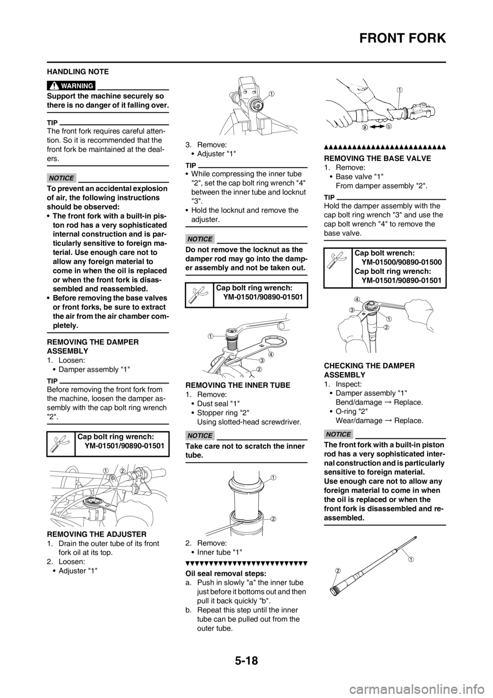
5-18
FRONT FORK
HANDLING NOTE
Support the machine securely so
there is no danger of it falling over.
The front fork requires careful atten-
tion. So it is recommended that the
front fork be maintained at the deal-
ers.
To prevent an accidental explosion
of air, the following instructions
should be observed:
• The front fork with a built-in pis-
ton rod has a very sophisticated
internal construction and is par-
ticularly sensitive to foreign ma-
terial. Use enough care not to
allow any foreign material to
come in when the oil is replaced
or when the front fork is disas-
sembled and reassembled.
• Before removing the base valves
or front forks, be sure to extract
the air from the air chamber com-
pletely.
REMOVING THE DAMPER
ASSEMBLY
1. Loosen:
• Damper assembly "1"
Before removing the front fork from
the machine, loosen the damper as-
sembly with the cap bolt ring wrench
"2".
REMOVING THE ADJUSTER
1. Drain the outer tube of its front
fork oil at its top.
2. Loosen:
•Adjuster "1"3. Remove:
•Adjuster "1"
• While compressing the inner tube
"2", set the cap bolt ring wrench "4"
between the inner tube and locknut
"3".
• Hold the locknut and remove the
adjuster.
Do not remove the locknut as the
damper rod may go into the damp-
er assembly and not be taken out.
REMOVING THE INNER TUBE
1. Remove:
• Dust seal "1"
• Stopper ring "2"
Using slotted-head screwdriver.
Take care not to scratch the inner
tube.
2. Remove:
• Inner tube "1"
Oil seal removal steps:
a. Push in slowly "a" the inner tube
just before it bottoms out and then
pull it back quickly "b".
b. Repeat this step until the inner
tube can be pulled out from the
outer tube.
REMOVING THE BASE VALVE
1. Remove:
• Base valve "1"
From damper assembly "2".
Hold the damper assembly with the
cap bolt ring wrench "3" and use the
cap bolt wrench "4" to remove the
base valve.
CHECKING THE DAMPER
ASSEMBLY
1. Inspect:
• Damper assembly "1"
Bend/damage → Replace.
• O-ring "2"
Wear/damage → Replace.
The front fork with a built-in piston
rod has a very sophisticated inter-
nal construction and is particularly
sensitive to foreign material.
Use enough care not to allow any
foreign material to come in when
the oil is replaced or when the
front fork is disassembled and re-
assembled.Cap bolt ring wrench:
YM-01501/90890-01501
Cap bolt ring wrench:
YM-01501/90890-01501
Cap bolt wrench:
YM-01500/90890-01500
Cap bolt ring wrench:
YM-01501/90890-01501