2013 VOLVO V60 tow
[x] Cancel search: towPage 308 of 422
07 During your journey
Towing and recovery
07
306
Recovery
Call a recovery service for recovery assistance.
IMPORTANT
Note that the car must always be transpor-
ted with the wheels rolling forward.
•An All Wheel Drive car (AWD) with raised
front suspension must not be towed at
speeds above 70 km/h. It should not be
towed further than 50 km.
ProCarManuals.com
Page 313 of 422
08 Wheels and tyres
General
08
* Option/accessory, for more information, see Introduction.311
Wear and maintenanceThe correct tyre pressure results in more even
wear, see page 317. Driving style, tyre pres-
sure, climate and road condition affect how
quickly your tyres age and wear. To avoid dif-
ferences in tread depth and to prevent wear
patterns arising, the front and rear wheels can
be switched with each other. A suitable dis-
tance for the first change is approx. 5000 km
and then at 10 000 km intervals. Volvo recom-
mends that you contact an authorised Volvo
workshop for checking if you are uncertain
about tread depth. If significant differences in
wear (>1 mm difference in tread depth)
between tyres have already occurred, the least
worn tyres must always be placed on the rear.
Understeer is normally easier to correct than
oversteer, and leads to the car continuing for-
wards in a straight line rather than having the
rear end skidding to one side, resulting in pos-
sible complete loss of control over the car. This
is why it is important for the rear wheels never
to lose grip before the front wheels.
Wheels should be stored lying down or hanging
up - and not standing up.
WARNING
A damaged tyre can lead to loss of control
of the car.
Tyres with tread wear indicators
G021829
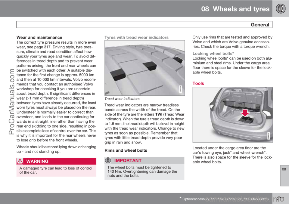
Tread wear indicators.
Tread wear indicators are narrow treadless
bands across the width of the tread. On the
side of the tyre are the letters TWI (Tread Wear
Indicator). When the tyre's tread depth is down
to 1.6 mm, the tread depth will be level in height
with the tread wear indicators. Change to new
tyres as soon as possible. Remember that
tyres with little tread depth provide very poor
grip in rain and snow.
Rims and wheel bolts
IMPORTANT
The wheel bolts must be tightened to
140 Nm. Overtightening can damage the
nuts and the bolts.
Only use rims that are tested and approved by
Volvo and which are Volvo genuine accesso-
ries. Check the torque with a torque wrench.
Locking wheel bolts*Locking wheel bolts* can be used on both alu-
minium and steel rims. Under the cargo area
floor there is space for the sleeve for the lock-
able wheel bolts.
Tools
Located under the cargo area floor are the
car's towing eye, jack* and wheel wrench*.
There is also space for the sleeve for the lock-
able wheel bolts.
ProCarManuals.com
Page 316 of 422
08 Wheels and tyres
Changing wheels
08
314* Option/accessory, for more information, see Introduction.
Spare wheel*
The following instructions are applicable
only if a spare wheel has been purchased as
an optional extra with the car. If the car does
not have a spare wheel, see page 321 for infor-
mation on temporary tyre sealing (TMK).
The spare wheel (Temporary spare) is only
intended for use temporarily and must be
replaced by an ordinary wheel as soon as pos-
sible. The car's handling may be altered by the
use of the spare wheel. The spare wheel is
smaller than the normal wheel. The car's
ground clearance is affected accordingly. Pay
attention to high kerbs and do not machine
wash the car. If the spare wheel is fitted on the
front axle, you cannot use snow chains at the
same time. On all-wheel drive cars the drive on
the rear axle can be disconnected. The spare
wheel must not be repaired. The correct tyre
pressure for the spare wheel is stated in the
tyre pressure table, see page 388.
IMPORTANT
Never drive faster than 80 km/h with a spare
wheel on the car.
IMPORTANT
The car must never be driven fitted with
more than one temporary spare wheel.
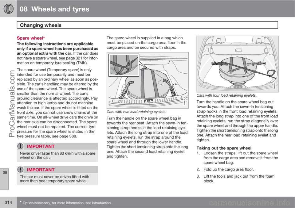
The spare wheel is supplied in a bag which
must be placed on the cargo area floor in the
cargo area and be secured with straps.
Cars with two load retaining eyelets.
Turn the handle on the spare wheel bag in
towards the rear seat. Attach the sewn-in ten-
sioning strap hooks in the load retaining eye-
lets. Attach the long strap into one of the load
retaining eyelets, run the strap around the
spare wheel and through the lower handle.
Tighten the short tensioning strap onto the long
one. Attach the second load retaining eyelet
and tighten.
Cars with four load retaining eyelets.
Turn the handle on the spare wheel bag out
towards you. Attach the sewn-in tensioning
strap hooks in the front load retaining eyelets.
Attach the long strap into one of the front load
retaining eyelets, run the strap diagonally over
the spare wheel and through the upper handle.
Tighten the short tensioning strap onto the long
one. Attach the rear load retaining eyelet and
tighten.
Taking out the spare wheel1. Loosen the straps, lift out the spare wheel
from the cargo area and remove it from the
spare wheel bag.
2. Fold up the cargo area floor.
3. Lift the tools and jack out from the foam
block.
ProCarManuals.com
Page 317 of 422

08 Wheels and tyres
Changing wheels
08
* Option/accessory, for more information, see Introduction.315 Removing
Set up the warning triangle, see page 318 if a
wheel must be replaced at a busy location. The
car and jack* must be on a firm horizontal sur-
face.
1. Apply the parking brake and engage
reverse gear, or position P if the car has an
automatic gearbox.
WARNING
Check that the jack is not damaged, that the
threads are thoroughly lubricated and that it
is free from dirt.
NOTE
Volvo recommends only using the jack* that
belongs to the car model in question, which
is indicated on the jack's label.
The label also indicates the jack's maximum
lift capacity at a specified minimum lifting
height.
2. Take out the jack*, wheel wrench* and
removal tool for wheel covers* located
under the cargo floor in the cargo area. If
another jack is selected, see page 328.
3. Place chocks in front of and behind the
wheels which will remain on the ground.Use heavy wooden blocks or large stones
for example.
4. Cars with steel rims have removable wheel
covers. Use the removal tool to hook in and
pull off any full-wheel wheel covers. Alter-
natively, the wheel covers can be pulled
away by hand.
5. Screw together the towing eye with the
wheel wrench* until the stop position as
illustrated below.
IMPORTANT
The towing eye must be screwed into all
threads in the wheel bolt wrench.
6. Loosen the wheel bolts ½-1 turn anticlock-
wise with the wheel wrench.
WARNING
Never position anything between the
ground and the jack, nor between the jack
and the car's jacking point.
7. There are two jacking points on each side
of the car. There is a recess in the plastic
cover at each point. Crank the foot of the
ProCarManuals.com
Page 336 of 422
09 Maintenance and service
Engine compartment 09
334
Filling
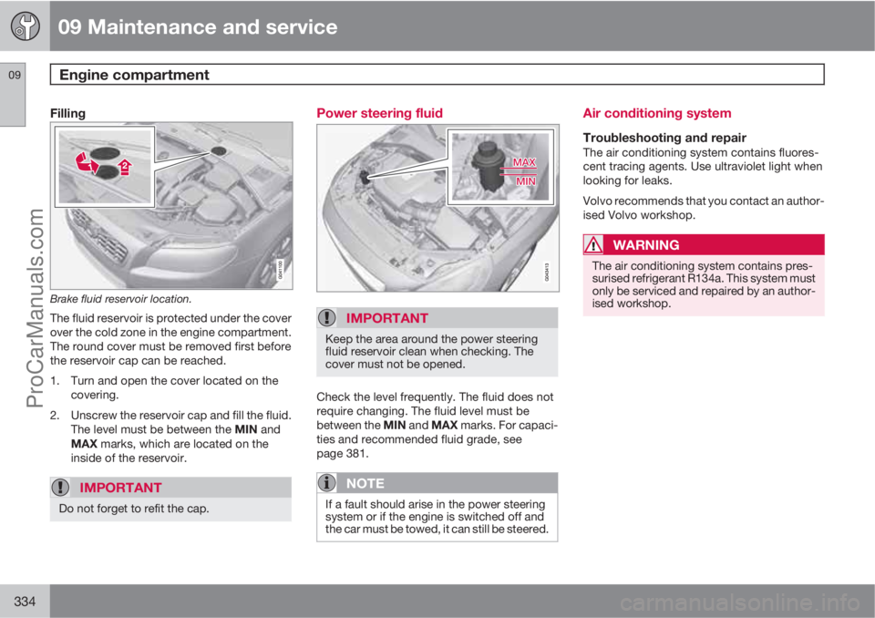
Brake fluid reservoir location.
The fluid reservoir is protected under the cover
over the cold zone in the engine compartment.
The round cover must be removed first before
the reservoir cap can be reached.
1. Turn and open the cover located on the
covering.
2. Unscrew the reservoir cap and fill the fluid.
The level must be between the MIN and
MAX marks, which are located on the
inside of the reservoir.
IMPORTANT
Do not forget to refit the cap.
Power steering fluid
IMPORTANT
Keep the area around the power steering
fluid reservoir clean when checking. The
cover must not be opened.
Check the level frequently. The fluid does not
require changing. The fluid level must be
between the MIN and MAX marks. For capaci-
ties and recommended fluid grade, see
page 381.
NOTE
If a fault should arise in the power steering
system or if the engine is switched off and
the car must be towed, it can still be steered.
Air conditioning system
Troubleshooting and repairThe air conditioning system contains fluores-
cent tracing agents. Use ultraviolet light when
looking for leaks.
Volvo recommends that you contact an author-
ised Volvo workshop.
WARNING
The air conditioning system contains pres-
surised refrigerant R134a. This system must
only be serviced and repaired by an author-
ised workshop.
ProCarManuals.com
Page 344 of 422

09 Maintenance and service
Wiper blades and washer fluid 09
342
Fold up the wiper arm when it is in service
position. Press the button located on the
wiper blade mounting and pull straight out
parallel with the wiper arm.
Slide in the new wiper blade until a "click"
is heard.
Check that the blade is firmly installed.
4. Fold the wiper arm back towards the wind-
screen.
The wipers return from service position to their
starting position when you briefly press the
START/STOP ENGINE button to set the car’s
electrical system to key position I (or when the
car is started).
G021763
NOTE
The wiper blades are different lengths. The
blade on the driver's side is longer than the
blade on the passenger side.
Replacing the wiper blades, rear window
1. Fold out the wiper arm.
2. Grip the inner section of the blade (by the
arrow).
3. Turn anticlockwise to use the blade's end
position against the wiper arm as a lever to
detach the blade more easily.
4. Press the new wiper blade into position.
Check that it is firmly installed.
5. Lower the wiper arm.
CleaningFor cleaning wiper blades and windscreen, see
page 361 and onwards.
IMPORTANT
Check the wiper blades regularly.
Neglected maintenance shortens the serv-
ice life of the wiper blades.
ProCarManuals.com
Page 358 of 422

09 Maintenance and service
Fuses 09
356* Option/accessory, for more information, see Introduction.
Box AFunctionA
--
Infotainment control module5
Audio control unit (ampli-
fier)*
Digital radio*; TV*10
Audio15
Telematics*; Bluetooth*5
--
Sunroof*; Interior lighting
roof; Climate sensor*;
Damper motors, air intake5
12 V socket, tunnel console15
Seat heating, rear right*15
Seat heating, rear left*15
--
Seat heating (passenger
side)15
Seat heating (driver's side)15
Box AFunctionA
Parking assistance*; Park-
ing camera*; Towbar control
module *
BLIS*5
AWD control module*15
Active chassis Four-C*10
Box BFunctionA
Rear window wiper15
--
Interior lighting; Driver's
door control panel, power
windows; Power seats,
front*; Remote controlled
garage door opener*7.5
Information display (DIM)5
Adaptive cruise control,
ACC*; collision warning sys-
tem*10
Interior lighting; Rain sensor7.5
Steering wheel module7.5
Box BFunctionA
Central locking system, fuel
filler flap10
Rear window washer15
Windscreen washers15
Unlocking, tailgate10
Folding head restraint*10
Fuel pump20
Movement detector alarm*;
Climate panel5
Steering lock15
Siren alarm*; Data link con-
nector OBDII5
--
Airbags10
Collision warning system*5
Accelerator pedal sensor,
PTC element air preheater*;
Dimming, interior rearview
mirror*; Seat heating, rear*7.5
ProCarManuals.com
Page 375 of 422
10 Specifications
Dimensions and weights
10
373 Weights
Kerb weight includes the driver, the fuel tank
90% full and all fluids.
The weight of passengers and accessories,
and towball load (when a trailer is hitched, see
table page 374) influences the payload and is
not included in the kerb weight.
Permitted max. load = Gross vehicle weight -
Kerb weight.
NOTE
The documented kerb weight applies to
cars in the standard version - i.e. a car with-
out extra equipment or accessories. This
means that for every accessory added the
loading capacity of the car is reduced cor-
respondingly by the weight of the acces-
sory.
Examples of accessories that reduce load-
ing capacity are the Kinetic/Momentum/
Summum equipment levels, as well as other
accessories such as Towbar, Load carriers,
Space box, Audio system, Auxiliary lamps,
GPS, Fuel-driven heater, Safety grille, Car-
pets, Cargo cover, Power seats, etc.
Weighing the car is a certain way of ascer-
taining the kerb weight of your own partic-
ular car.
WARNING
The car's driving characteristics change
depending on how heavily it is loaded and
how the load is distributed.
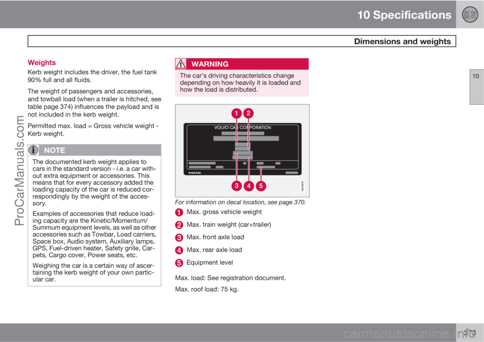
For information on decal location, see page 370.
Max. gross vehicle weight
Max. train weight (car+trailer)
Max. front axle load
Max. rear axle load
Equipment level
Max. load: See registration document.
Max. roof load: 75 kg.
ProCarManuals.com