2013 SUZUKI ERTIGA automatic
[x] Cancel search: automaticPage 7 of 207

Downloaded from www.Manualslib.com manuals search engine 60MK0-14E
SERVICE STATION GUIDE1. Fuel (see section 1)
2. Engine hood (see section 5)
3. Tire changing tools (see section 8)
4. Engine oil dipstick
(see section 7)
5. Automatic transaxle fluid dipstick
6. Engine coolant (see section 7)
7. Windshield washer fluid
(see section 7)
8. Battery (see section 7)
9. Tire pressure (see Tire Information
Label on driver’s door lock pillar)
10. Spare tire (see section 7)
60MK022
2
110
3 9
6
2
4785
1
Page 14 of 207

Downloaded from www.Manualslib.com manuals search engine 1-1FUEL RECOMMENDATION
60MK0-14E
Fuel RecommendationGasoline Engine
60MK040
If your vehicle is not fitted with a restrictor
in the fuel filler pipe then you may use
leaded or unleaded gasoline with an
octane number (RON) of 85 or higher.
Note, it is preferable to use unleaded gaso-
line.
If your vehicle is fitted with a restrictor in
the fuel filler pipe then you must use
unleaded gasoline with an octane number
(RON) of 91 or higher (or RON of 95 or
higher if it is stated on the fuel filler lid).
These vehicles are also identified by a
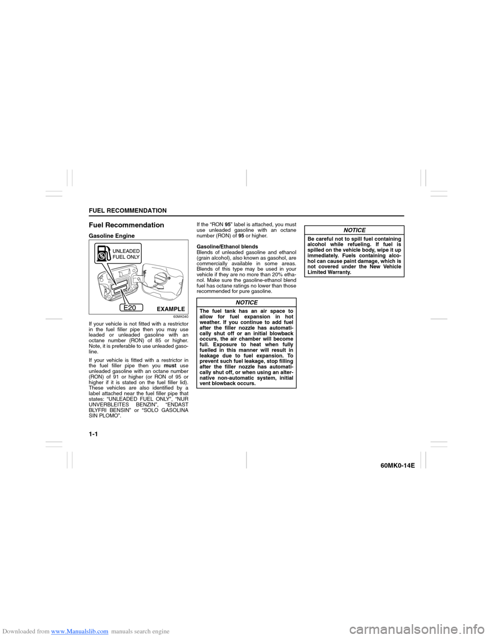
label attached near the fuel filler pipe that
states: “UNLEADED FUEL ONLY”, “NUR
UNVERBLEITES BENZIN”, “ENDAST
BLYFRI BENSIN” or “SOLO GASOLINA
SIN PLOMO”.If the “RON 95” label is attached, you must
use unleaded gasoline with an octane
number (RON) of 95 or higher.
Gasoline/Ethanol blends
Blends of unleaded gasoline and ethanol
(grain alcohol), also known as gasohol, are
commercially available in some areas.
Blends of this type may be used in your
vehicle if they are no more than 20% etha-
nol. Make sure the gasoline-ethanol blend
fuel has octane ratings no lower than those
recommended for pure gasoline.
EXAMPLE
NOTICE
The fuel tank has an air space to
allow for fuel expansion in hot
weather. If you continue to add fuel
after the filler nozzle has automati-
cally shut off or an initial blowback
occurs, the air chamber will become
full. Exposure to heat when fully
fuelled in this manner will result in
leakage due to fuel expansion. To
prevent such fuel leakage, stop filling
after the filler nozzle has automati-
cally shut off, or when using an alter-
native non-automatic system, initial
vent blowback occurs.
NOTICE
Be careful not to spill fuel containing
alcohol while refueling. If fuel is
spilled on the vehicle body, wipe it up
immediately. Fuels containing alco-
hol can cause paint damage, which is
not covered under the New Vehicle
Limited Warranty.
Page 21 of 207

Downloaded from www.Manualslib.com manuals search engine 2-6
BEFORE DRIVING
60MK0-14E
When the doors are unlocked:
The turn signal lights will flash twice.
If the interior light switch is in the
“DOOR” position, the interior light will
turn on for about 15 seconds and then
fade out. If you insert the key into the
ignition switch during this time, the light
will start to fade out immediately.
Be sure the doors are locked after you
operate the “LOCK” button (1).
NOTE:
If no door is opened within about 30 sec-
onds after the “UNLOCK” button (2) is
operated, the doors will automatically lock
again.
NOTE:
The maximum operating distance of the
keyless entry system transmitter is about
5 m (16 ft.), but this can vary depending
on the surroundings, especially near
other transmitting devices such as radio
towers or CB (Citizen’s Band) radios.
The door locks cannot be operated with
the transmitter, if the ignition key is
inserted in the ignition switch.
When any door is open, the door locks
can be operated only unlock with the
transmitter, and the turn signal light will
not flash.
If you lose one of the transmitters, ask
your SUZUKI dealer as soon as possible
for a replacement. Be sure to have your
dealer program the new transmitter codein your vehicle’s memory so that the old
code is erased.
Replacement of the BatteryIf the transmitter becomes unreliable,
replace the battery.
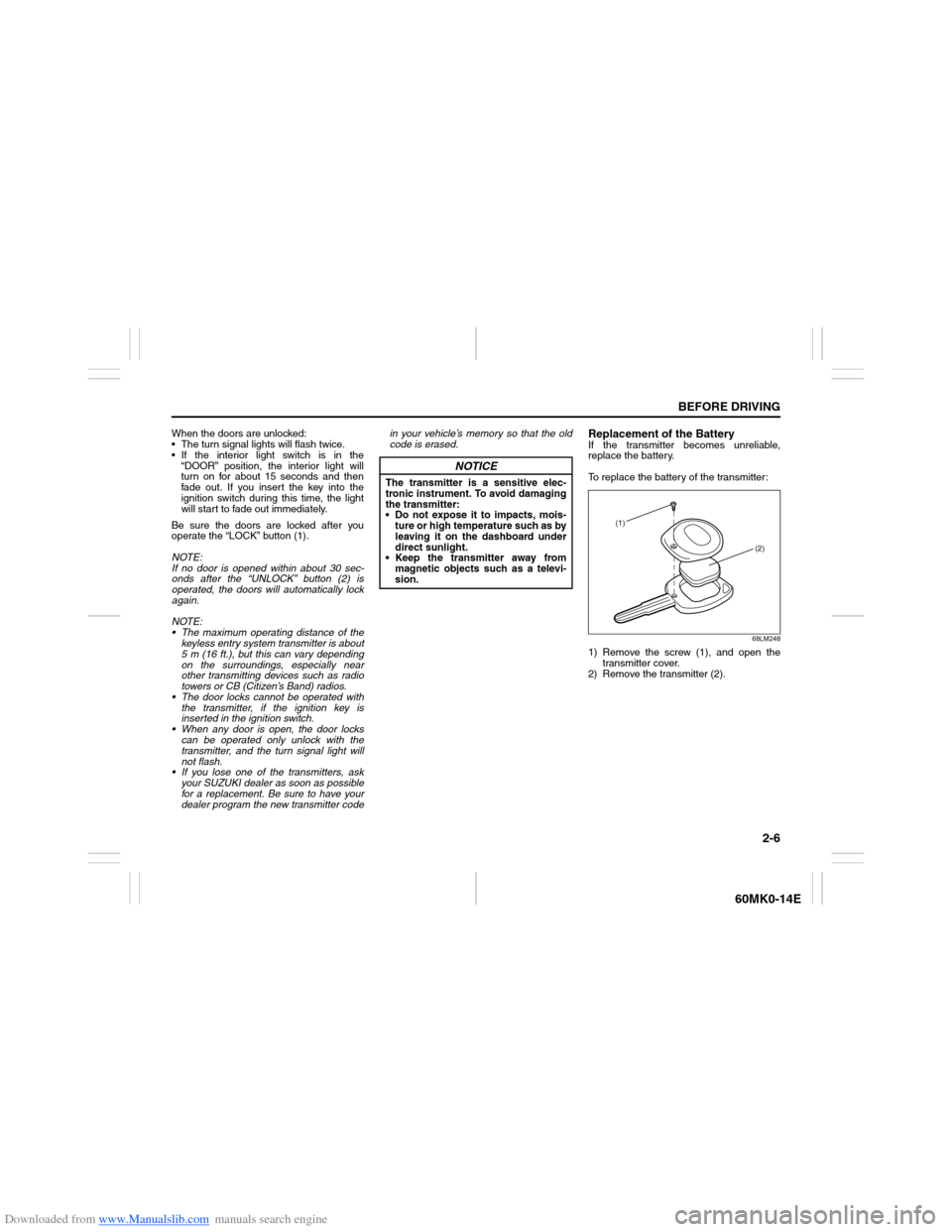
To replace the battery of the transmitter:
68LM248
1) Remove the screw (1), and open the
transmitter cover.
2) Remove the transmitter (2).
NOTICE
The transmitter is a sensitive elec-
tronic instrument. To avoid damaging
the transmitter:
Do not expose it to impacts, mois-
ture or high temperature such as by
leaving it on the dashboard under
direct sunlight.
Keep the transmitter away from
magnetic objects such as a televi-
sion.
(1)
(2)
Page 23 of 207

Downloaded from www.Manualslib.com manuals search engine 2-8
BEFORE DRIVING
60MK0-14E
NOTE:
The theft deterrent alarm system gener-
ates alarms when any of the predeter-
mined conditions is met. However, the
system does not have any function of
blocking unauthorized entry into your
vehicle.
Always use the keyless entry system
transmitter to unlock the doors when the
theft deterrent alarm system has been
armed. Using a key instead will trigger
the alarm.
If a person who does not know the theft
deterrent alarm system is going to drive
your vehicle, we recommend you explain
the system and its operation to the per-
son, or disable the system beforehand.
Mistakenly triggering the alarm may
cause a nuisance to others.
Even if the theft deterrent alarm system
is armed, you should still be careful to
guard against theft. Do not leave money
or things of value in your vehicle.How to arm the theft deterrent alarm
system (when enabled)
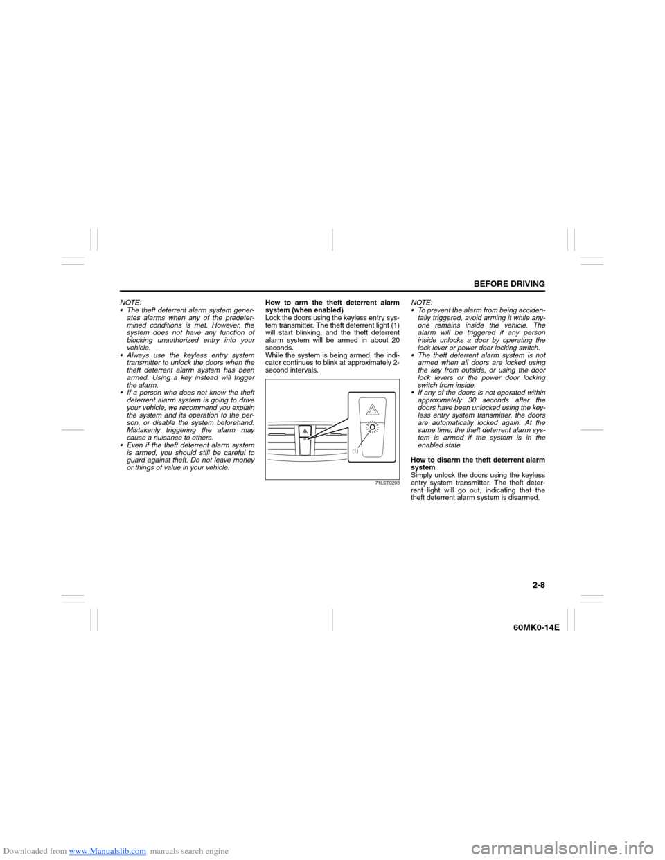
Lock the doors using the keyless entry sys-
tem transmitter. The theft deterrent light (1)
will start blinking, and the theft deterrent
alarm system will be armed in about 20
seconds.
While the system is being armed, the indi-
cator continues to blink at approximately 2-
second intervals.
71LST0203
NOTE:
To prevent the alarm from being acciden-
tally triggered, avoid arming it while any-
one remains inside the vehicle. The
alarm will be triggered if any person
inside unlocks a door by operating the
lock lever or power door locking switch.
The theft deterrent alarm system is not
armed when all doors are locked using
the key from outside, or using the door
lock levers or the power door locking
switch from inside.
If any of the doors is not operated within
approximately 30 seconds after the
doors have been unlocked using the key-
less entry system transmitter, the doors
are automatically locked again. At the
same time, the theft deterrent alarm sys-
tem is armed if the system is in the
enabled state.
How to disarm the theft deterrent alarm
system
Simply unlock the doors using the keyless
entry system transmitter. The theft deter-
rent light will go out, indicating that the
theft deterrent alarm system is disarmed.
(1)
Page 40 of 207

Downloaded from www.Manualslib.com manuals search engine 2-25BEFORE DRIVING
60MK0-14E
Driver’s Seat Belt Reminder
60MK026
When the driver does not buckle his or her
seat belt with the ignition switch in the “ON”
position, the driver’s seat belt reminder
light in the instrument cluster will blink until
the driver’s seat belt is buckled.
The reminder will be automatically can-
celed when the driver’s seat belt is buckled
or the ignition switch is turned off.
Shoulder Anchor Height Adjuster
(if equipped)
64J198
Adjust the shoulder anchor height so that
the shoulder belt rides on the center of the
outboard shoulder. To move upward, slide
the anchor up. To move downward, slide
the anchor down while pulling the lock
knob out. After adjustment, make sure that
the anchor is securely locked.
EXAMPLE
WARNING
It is absolutely essential that the
driver and passengers wear their seat
belts at all times. Persons who are
not wearing seat belts have a much
greater risk of injury if an accident
occurs. Make a regular habit of buck-
ling your seat belt before putting the
key in the ignition.
WARNING
Be sure that the shoulder belt is posi-
tioned on the center of the outside
shoulder. The belt should be away
from your face and neck, but not fall-
ing off your shoulder. Misadjustment
of the belt could reduce the effective-
ness of the safety belt in a crash.
EXAMPLE
Page 55 of 207

Downloaded from www.Manualslib.com manuals search engine 2-40
BEFORE DRIVING
60MK0-14E
Charging Light
50G052
This light comes on when the ignition
switch is turned to the “ON” position, and
goes out when the engine is started. The
light will come on and remain on if there is
something wrong with the battery charging
system. If the light comes on when the
engine is running, the charging system
should be inspected immediately by your
SUZUKI dealer.Driver’s Seat Belt Reminder Light
60G049
If the driver’s seat belt is unbuckled when
the ignition switch is turned to the “ON”
position, this light will blink until the driver’s
seat belt is buckled.
For details about the seat belt reminder,
refer to “Seat Belts and Child Restraint
Systems” in this section.
“AIR BAG” Light (if equipped)
63J030
This light blinks or comes on for several
seconds when the ignition switch is turned
to the “ON” position so you can check if the
light is working.
The light will come on and stay on if there
is a problem in the air bag system or the
seat belt pretensioner system (if
equipped).
Malfunction Indicator Light
65D530
Your vehicle has a computer-controlled
emission control system. A malfunction
indicator light is provided on the instrument
panel to indicate when it is necessary to
have the emission control system serviced.
The malfunction indicator light comes on
when the ignition switch is turned to the
“ON” position to let you know the light is
working and goes out when the engine is
started.
If the malfunction indicator light comes on
or blinks when the engine is running, there
is a damage in the emission control sys-
tem.
Bring the vehicle to your SUZUKI dealer to
have the damage fixed.
Also, if this light comes on when the engine
is running, there is the problem with the
automatic transaxle system. Ask your
SUZUKI dealer to have the system
inspected.
WARNING
If the “AIR BAG” light does not blink
or come on briefly when the ignition
switch is turned to the “ON” position,
stays on for more than 10 seconds,
or comes on while driving, the air bag
system or the seat belt pretensioner
system (if equipped) may not work
properly. Have both systems
inspected by an authorized SUZUKI
dealer.
Page 60 of 207

Downloaded from www.Manualslib.com manuals search engine 2-45BEFORE DRIVING
60MK0-14E
Brightness Control
68LM227
When the ignition switch is turned to the
“ON” position, the pointer lights come on.
Your vehicle has a system to automatically
dim the brightness of the instrument panel
lights when the position lights or headlights
are on.
When the position lights and/or headlights
are ON, you can control the meter illumina-
tion intensity.
To increase the brightness of the instru-
ment panel lights, turn the brightness con-
trol knob (1) clockwise.
To reduce the brightness of the instrument
panel lights, turn the brightness control
knob (1) counterclockwise.
60MH025
NOTE:
If you do not turn the brightness control
knob within about 10 seconds of activat-
ing the brightness control display, the
brightness control display will be can-
celed automatically.
When you reconnect the battery, the
brightness of the instrument panel lights
will be reinitialized. Readjust the bright-
ness according to your preference.
(1)
EXAMPLE
WARNING
If you attempt to adjust the display
while driving, you could lose control
of the vehicle.
Do not attempt to adjust the display
while driving.EXAMPLE
(Brightest)
(Initial setting)
(Dimmest)
Page 61 of 207

Downloaded from www.Manualslib.com manuals search engine 2-46
BEFORE DRIVING
60MK0-14E
Information Displaywith tachometer
60MK028
without tachometer
60MK029
(1) Trip meter selector knob
(2) Indicator selector knob
(3) Information display
When the ignition switch is in the “ON”
position, the information display shows the
following information.
Display (A)
Thermometer (if equipped)
Display (B)
(for automatic transaxle vehicle)
Transaxle selector position indicator
Display (C)
Trip meter / Instantaneous fuel consump-
tion / Average fuel consumption / Driving
range
Display (D)
Odometer
Display (E)
Clock
Thermometer (if equipped)When the ignition switch is in the “ON”
position, the display (A) shows the ther-
mometer.
The thermometer indicates the outside
temperature.
68LM258
If the outside temperature nears freezing,
the mark (a) will appear on the display.
NOTE:
The outside temperature indication is not
the actual outside temperature when
driving at low speed, or when stopped.
If there is something wrong with the ther-
mometer, or just after the ignition switch
is turned to the “ON” position, the display
may not indicate the outside tempera-
ture.
(1) (2)(3)
(D)(B) (A)
(C)(E)
EXAMPLE(1)
(2)
(3)(C)
(D)
(E)
EXAMPLE
(a)
EXAMPLE