2013 SUBARU FORESTER shift
[x] Cancel search: shiftPage 19 of 436

16 &Instrument panel
1) Door locks (page 2-4)
2) Outside mirror switch (page 3-43)
3) Illumination brightness control
(page 3-31)
4) Light control lever (page 3-29)
5) Combination meter (page 3-6)
6) Wiper control lever (page 3-33)
7) Hazard warning flasher switch (page 3-5)
8) Audio (page 5-1)
9) Shift lever (MT) (page 7-13)/ Select lever (AT) (page 7-15)
10) Climate control (page 4-1)
11) Cruise control (page 7-32)
12) Horn (page 3-47)
13) SRS airbag (page 1-33)
14) Tilt/telescopic steering (page 3-46)
15) Hands-free switches (page 5-42)
16) Audio control buttons (page 5-37)
17) Fuse box (page 11-44)
18) Vehicle Dynamics Control OFF switch (page 7-27)
19) Hood lock release knob (page 11-5)
20) Power windows (page 2-20)
Page 135 of 436

3-24Instruments and controls
function normally. &SPORT mode indicator
light (AT models)
When the select lever is moved to the
manual gate, the SPORT mode is se-
lected and the indicator light illuminates.
Refer to “SPORT mode ”F 7-20.
& Select lever and gear posi-
tion indicator (AT models)
Type A
Type B
This indicator shows the position of the
select lever.
When the manual mode is selected, the
gear position indicator (which shows the
current gear selection) and the upshift/
downshift indicator light up. Refer to“ Automatic transmission ”F 7-15.
& Turn signal indicator lights
These lights show the operation of the turn
signal or lane change signal.
If the indicator lights do not blink or blink
rapidly, any of the turn signal light bulbs
may be burned out. Replace the bulb as
soon as possible. Refer to “Replacing
bulbs ”F 11-45. &
High beam indicator light
This light shows that the headlights are in
the high beam mode.
This indicator light also illuminates when
the headlight flasher is operated. &Cruise control indica-
tor light
This light illuminates when the “CRUISE ”
main switch is pressed to activate the
cruise control function. For details, refer to“ To set cruise control ”F 7-32.
CAUTION
If the CHECK ENGINE warning light/
malfunction indicator light illumi-
nates, the cruise control indicator
light flashes at the same time. At
this time, avoid driving at high
speed and have your vehicle in-
spected at a SUBARU dealer as
soon as possible.
NOTE
If you press the “CRUISE ”main switch
button while turning the ignition switch “ ON ”, the cruise control function is
deactivated and the cruise control
Page 147 of 436

3-36Instruments and controls
mittently at intervals corresponding to the
vehicle speed (longer when the vehicle
speed is low; shorter when the vehicle
speed is high).
When you subsequently shift the trans-
mission into reverse, the rear wiper will
automatically switch to continuous opera-
tion. When the transmission is shifted to a
position other than reverse, the rear wiper
will return to intermittent operation. !Washer
To wash the rear window while the rear
wiper is operating, turn the knob upward tothe “
”position. The washer fluid sprays
until you release the knob.
To wash the rear window when the rear
wiper is not in use, turn the knob down-
ward to the “
”position. The washer fluid
sprays, and 2 seconds later the rear wiper
operates. Releasing the knob stops the
washer fluid spray, and 3 seconds later
the rear wiper stops. Mirrors
Always check that the inside and outside
mirrors are properly adjusted before you
start driving. &
Inside mirror
The inside mirror has a day and night
position. Pull the tab at the bottom of the
mirror toward you for the night position.
Push it away for the day position. The
night position reduces glare from head-
lights of vehicles behind you. &
Auto-dimming mirror/com-
pass (if equipped)
1) Auto dimming indicator
2) Left (mirror) button
3) Photosensor
4) Right (compass) button
5) Compass display
The auto-dimming mirror has an anti-glare
feature which automatically reduces glare
coming from headlights of vehicles behind
you. It also contains a built-in compass. . By pressing and releasing the left
button, the automatic dimming function is
toggled on or off. When the automatic
dimming function is on, the auto dimming
indicator light (green) located on the left
button will illuminate. . By pressing and releasing the right
Page 148 of 436

button, the compass display is toggled on
or off. When the compass is on, an
illuminated compass reading will appear
in the upper right corner of the mirror.
Even with the mirror in anti-glare mode,
the mirror surface turns bright if the
transmission is shifted into reverse. This
is to ensure good rearward visibility duringreversing. !Photosensors
The mirror has a photosensor attached on
both the front and back sides. If the glare
from the headlights of vehicles behind you
strikes the mirror, these sensors detect it
and make the reflection surface of the
mirror dimmer to help prevent you from
being blinded. For this reason, use care
not to cover the sensors with stickers, or other similar items. Periodically wipe the
sensors clean using a piece of dry soft
cotton cloth or an applicator. !
Compass zone adjustment
Compass calibration zones
1. The zone setting is factory preset to
Zone 8. Refer to the “Compass calibration
zones ”map shown above to verify that the
compass zone setting is correct for your
geographical location.
2. Press and hold the right button for 3
seconds then release, and the word“ ZONE ”will briefly appear and then the
zone number will be displayed.
3. Press the right-hand button repeatedly
to cycle the display through all possible
zone settings. Stop cycling when the
correct zone setting for your location is displayed.
4. Releasing the button for 3 seconds will
exit the zone setting mode. !
Compass calibration
1. For optimum calibration, switch off all
nonessential electrical accessories (rear
window defogger, heater/air conditioning
system, spotlight, etc.) and ensure all
doors are shut.
2. Drive to an open, level area away from
large metallic objects or structures and
make certain the ignition switch is in the“ ON ”position.
3. Press and hold the right button for 6 - 7
seconds then release, and the compass
will enter the calibration mode. “CAL ”and
direction will be displayed.
4. Drive slowly in a circle until “CAL ”
disappears from the display (approxi-
mately two to three circles). The compass
is now calibrated.
5. Further calibration may be necessary
should outside influences cause the mirror
to read inaccurately. You will know that
this has occurred if your compass begins
to read in only limited directions. Should
you encounter this situation, return to step
one of the above procedure and recali-
brate the mirror. Instruments and controls
3-37
– CONTINUED –
Page 149 of 436

3-38Instruments and controls
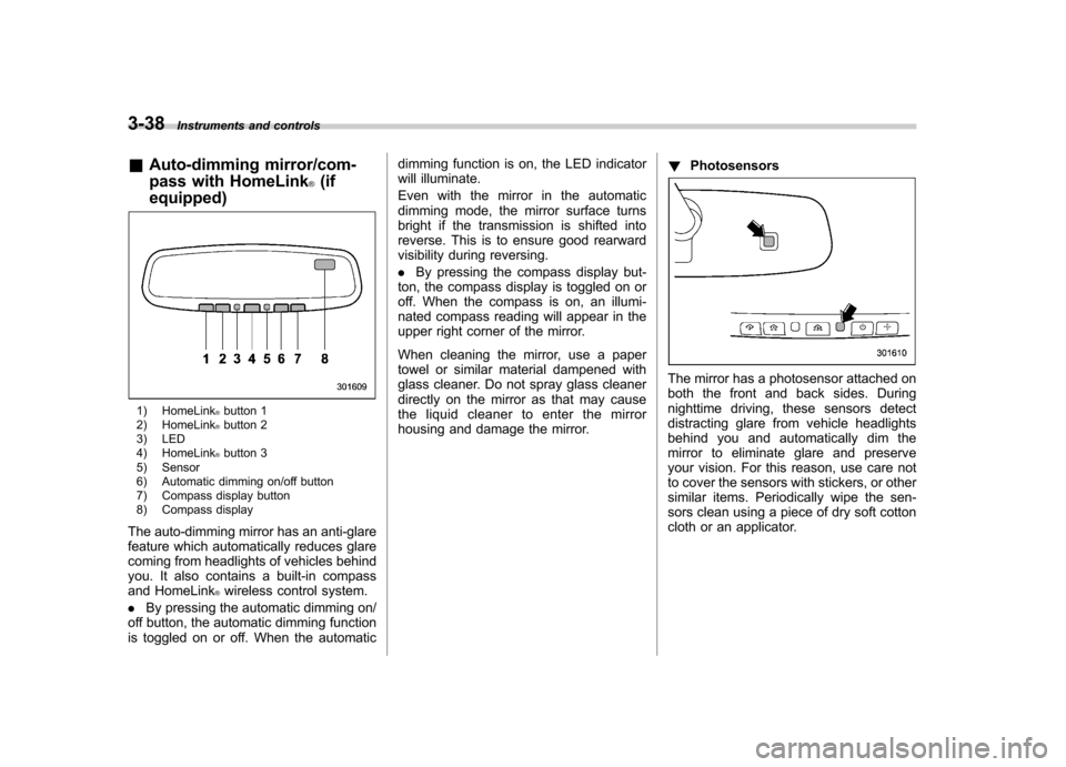
& Auto-dimming mirror/com-
pass with HomeLink
®(if
equipped)
1) HomeLink®button 1
2) HomeLink®button 2
3) LED
4) HomeLink
®button 3
5) Sensor
6) Automatic dimming on/off button
7) Compass display button
8) Compass display
The auto-dimming mirror has an anti-glare
feature which automatically reduces glare
coming from headlights of vehicles behind
you. It also contains a built-in compass
and HomeLink
®wireless control system.
. By pressing the automatic dimming on/
off button, the automatic dimming function
is toggled on or off. When the automatic dimming function is on, the LED indicator
will illuminate.
Even with the mirror in the automatic
dimming mode, the mirror surface turns
bright if the transmission is shifted into
reverse. This is to ensure good rearward
visibility during reversing. .
By pressing the compass display but-
ton, the compass display is toggled on or
off. When the compass is on, an illumi-
nated compass reading will appear in the
upper right corner of the mirror.
When cleaning the mirror, use a paper
towel or similar material dampened with
glass cleaner. Do not spray glass cleaner
directly on the mirror as that may cause
the liquid cleaner to enter the mirror
housing and damage the mirror. !
Photosensors
The mirror has a photosensor attached on
both the front and back sides. During
nighttime driving, these sensors detect
distracting glare from vehicle headlights
behind you and automatically dim the
mirror to eliminate glare and preserve
your vision. For this reason, use care not
to cover the sensors with stickers, or other
similar items. Periodically wipe the sen-
sors clean using a piece of dry soft cotton
cloth or an applicator.
Page 228 of 436

!Deleting registered cell phone from
the list
1. Select the “DELETE ”menu.
2. Select a cell phone to be deleted by
performing either of the following proce-dures. –Operate the “TUNE/TRACK/CH ”
dial. – Press the talk switch
and say
the voice tag.
3. Select the “CONFIRM ”menu. “DE-
LETED ”is displayed, the data is deleted
and the mode changes to the “PHONE
SETUP ”mode.
! System setup
After selecting the “SYSTEM SETUP ”
menu, perform the following procedures.
You can select the following menus only
by operating the “TUNE/TRACK/CH ”dial.
! Setting guidance volume
To set the guidance volume, perform the
following procedure.
1. Select the “GUIDANCE VOL ”/“ GUI-
DANCE VOLUME ”menu.
2. Set the guidance volume by operating the “TUNE/TRACK/CH ”dial. !
Initializing the registered data
To initialize the registered data, perform
the following procedure.
1. Select the “INITIALIZE ”menu.
2. Select the “CONFIRM ”menu. First
“ PLEASE WAIT ”, then “INITIALIZED ”is
displayed. The registered data is initia-
lized and the mode changes to the lastmode. ! Selecting language
To select the language, perform the
following procedure.
1. Select the “SEL LANGUAGE ”/“ SE-
LECT LANGUAGE ”menu.
2. Select the desired language by oper-
ating the “TUNE/TRACK/CH ”dial. Screensaver (type D audio)
If the following operations are not per-
formed for more than 30 seconds while
the audio is ON, the screensaver will bedisplayed. .
Operate any button or dial
. Shift the shift lever/select lever to the
“ R ”position
. A cell phone registered in the Hands-
free system is called
If one of the following operations is
performed, the screensaver turns off and
the operation screen will be displayed. . A cell phone registered in the Hands-
free system is called. The update for satellite radio starts.
. The update for satellite radio stops.
If one of the following operations is
performed, the screensaver turns off.
However, the operation screen will not
be displayed. . Operate any button or any dial in a
condition other than the following condi- tions
–Pressing the
button while a
mode other than the CD mode is selected – Pressing the volume control buttons
of the audio control buttons Audio
5-55
– CONTINUED –
Page 239 of 436

6-10Interior equipment
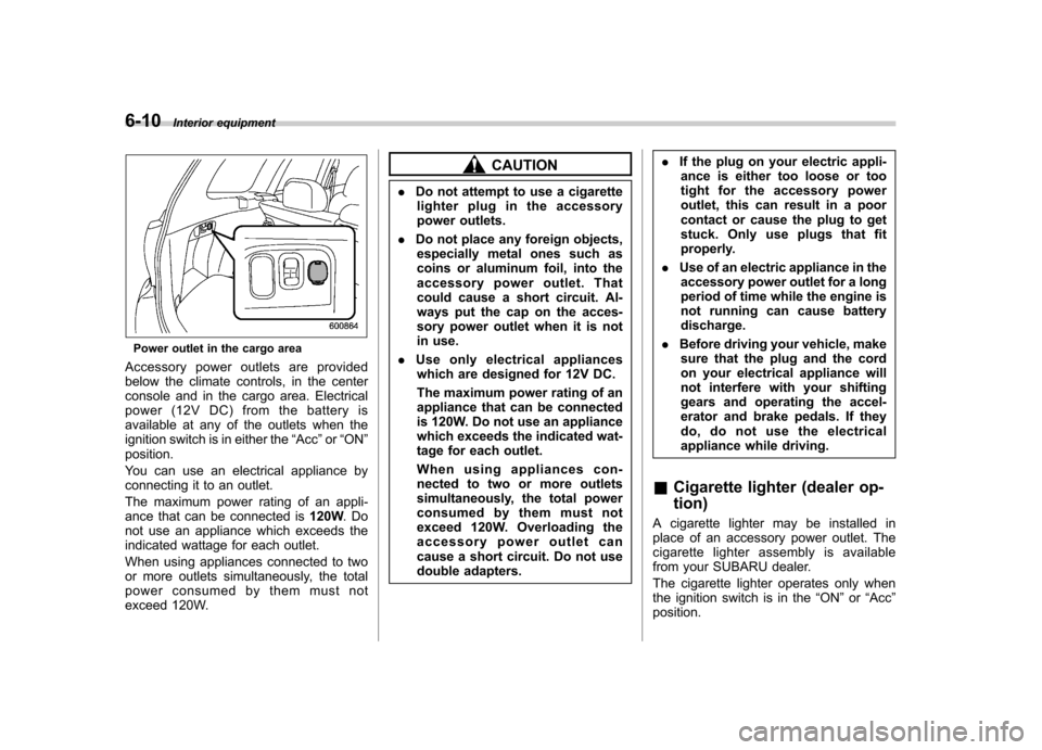
Power outlet in the cargo area
Accessory power outlets are provided
below the climate controls, in the center
console and in the cargo area. Electrical
power (12V DC) from the battery is
available at any of the outlets when the
ignition switch is in either the “Acc ”or “ON ”
position.
You can use an electrical appliance by
connecting it to an outlet.
The maximum power rating of an appli-
ance that can be connected is 120W.Do
not use an appliance which exceeds the
indicated wattage for each outlet.
When using appliances connected to two
or more outlets simultaneously, the total
power consumed by them must not
exceed 120W.
CAUTION
. Do not attempt to use a cigarette
lighter plug in the accessory
power outlets.
. Do not place any foreign objects,
especially metal ones such as
coins or aluminum foil, into the
accessory power outlet. That
could cause a short circuit. Al-
ways put the cap on the acces-
sory power outlet when it is not
in use.
. Use only electrical appliances
which are designed for 12V DC.
The maximum power rating of an
appliance that can be connected
is 120W. Do not use an appliance
which exceeds the indicated wat-
tage for each outlet.
When using appliances con-
nected to two or more outlets
simultaneously, the total power
consumed by them must not
exceed 120W. Overloading the
accessory power outlet can
cause a short circuit. Do not use
double adapters. .
If the plug on your electric appli-
ance is either too loose or too
tight for the accessory power
outlet, this can result in a poor
contact or cause the plug to get
stuck. Only use plugs that fit
properly.
. Use of an electric appliance in the
accessory power outlet for a long
period of time while the engine is
not running can cause batterydischarge.
. Before driving your vehicle, make
sure that the plug and the cord
on your electrical appliance will
not interfere with your shifting
gears and operating the accel-
erator and brake pedals. If they
do, do not use the electrical
appliance while driving.
& Cigarette lighter (dealer op- tion)
A cigarette lighter may be installed in
place of an accessory power outlet. The
cigarette lighter assembly is available
from your SUBARU dealer.
The cigarette lighter operates only when
the ignition switch is in the “ON ”or “Acc ”
position.
Page 246 of 436

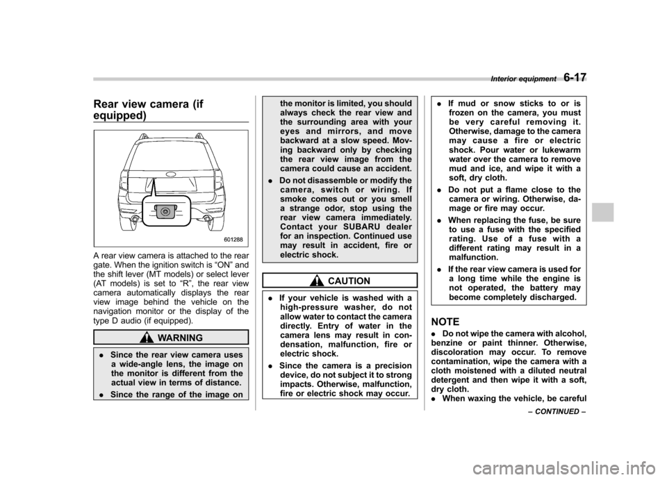
Rear view camera (if equipped)
A rear view camera is attached to the rear
gate. When the ignition switch is“ON ”and
the shift lever (MT models) or select lever
(AT models) is set to “R ”, the rear view
camera automatically displays the rear
view image behind the vehicle on the
navigation monitor or the display of the
type D audio (if equipped).
WARNING
. Since the rear view camera uses
a wide-angle lens, the image on
the monitor is different from the
actual view in terms of distance.
. Since the range of the image on the monitor is limited, you should
always check the rear view and
the surrounding area with your
eyes and mirrors, and move
backward at a slow speed. Mov-
ing backward only by checking
the rear view image from the
camera could cause an accident.
. Do not disassemble or modify the
camera, switch or wiring. If
smoke comes out or you smell
a strange odor, stop using the
rear view camera immediately.
Contact your SUBARU dealer
for an inspection. Continued use
may result in accident, fire or
electric shock.
CAUTION
. If your vehicle is washed with a
high-pressure washer, do not
allow water to contact the camera
directly. Entry of water in the
camera lens may result in con-
densation, malfunction, fire or
electric shock.
. Since the camera is a precision
device, do not subject it to strong
impacts. Otherwise, malfunction,
fire or electric shock may occur. .
If mud or snow sticks to or is
frozen on the camera, you must
be very careful removing it.
Otherwise, damage to the camera
may cause a fire or electric
shock. Pour water or lukewarm
water over the camera to remove
mud and ice, and wipe it with a
soft, dry cloth.
. Do not put a flame close to the
camera or wiring. Otherwise, da-
mage or fire may occur.
. When replacing the fuse, be sure
to use a fuse with the specified
rating. Use of a fuse with a
different rating may result in amalfunction.
. If the rear view camera is used for
a long time while the engine is
not operated, the battery may
become completely discharged.
NOTE . Do not wipe the camera with alcohol,
benzine or paint thinner. Otherwise,
discoloration may occur. To remove
contamination, wipe the camera with a
cloth moistened with a diluted neutral
detergent and then wipe it with a soft,
dry cloth.. When waxing the vehicle, be careful Interior equipment
6-17
– CONTINUED –